EP2719459B1 - Procédé et dispositif de commande de la pression dans un canal micro- ou mésofluidique - Google Patents
Procédé et dispositif de commande de la pression dans un canal micro- ou mésofluidique Download PDFInfo
- Publication number
- EP2719459B1 EP2719459B1 EP13004877.0A EP13004877A EP2719459B1 EP 2719459 B1 EP2719459 B1 EP 2719459B1 EP 13004877 A EP13004877 A EP 13004877A EP 2719459 B1 EP2719459 B1 EP 2719459B1
- Authority
- EP
- European Patent Office
- Prior art keywords
- valve
- pressure
- control
- pulse
- valves
- Prior art date
- Legal status (The legal status is an assumption and is not a legal conclusion. Google has not performed a legal analysis and makes no representation as to the accuracy of the status listed.)
- Active
Links
Images

Classifications
-
- B—PERFORMING OPERATIONS; TRANSPORTING
- B01—PHYSICAL OR CHEMICAL PROCESSES OR APPARATUS IN GENERAL
- B01L—CHEMICAL OR PHYSICAL LABORATORY APPARATUS FOR GENERAL USE
- B01L3/00—Containers or dishes for laboratory use, e.g. laboratory glassware; Droppers
- B01L3/50—Containers for the purpose of retaining a material to be analysed, e.g. test tubes
- B01L3/502—Containers for the purpose of retaining a material to be analysed, e.g. test tubes with fluid transport, e.g. in multi-compartment structures
- B01L3/5027—Containers for the purpose of retaining a material to be analysed, e.g. test tubes with fluid transport, e.g. in multi-compartment structures by integrated microfluidic structures, i.e. dimensions of channels and chambers are such that surface tension forces are important, e.g. lab-on-a-chip
- B01L3/502738—Containers for the purpose of retaining a material to be analysed, e.g. test tubes with fluid transport, e.g. in multi-compartment structures by integrated microfluidic structures, i.e. dimensions of channels and chambers are such that surface tension forces are important, e.g. lab-on-a-chip characterised by integrated valves
-
- B—PERFORMING OPERATIONS; TRANSPORTING
- B01—PHYSICAL OR CHEMICAL PROCESSES OR APPARATUS IN GENERAL
- B01L—CHEMICAL OR PHYSICAL LABORATORY APPARATUS FOR GENERAL USE
- B01L2300/00—Additional constructional details
- B01L2300/14—Means for pressure control
Definitions
- the invention relates to a method and a device for regulating the pressure in a micro- or mesofluidic channel.
- microfluidic channel system There is a microfluidic channel system according to the prior art WO 2004/103566 , The pressure is generated by a pressure divider system in which two valves are connected in series.
- the publication FR2855076A1 describes a method for adjusting a pressure in a fluid passage, wherein two valves are provided, one of which is preselected with a certain degree of opening and then remains in this setting, while a second valve is controlled.
- a disadvantage of the prior art is that there is a high gas consumption and a poor response of the pressure change to a change in a valve opening.
- the object of the present invention is to improve the disadvantages of the prior art. In particular, the best possible control properties should be achieved.
- a micro- or mesofluidic channel is preferably a small container (micro: diameter / width of the container is less than 1 mm, meso: diameter / width is a few millimeters, about 1 to 10 mm), in which the pressure is reproducibly controlled and so reproducible movement and positioning of objects in the channel, e.g. B. of cells or molecules is possible.
- a mesofluidic channel or mesochannel is always understood as mentioned, even if only one microfluidic channel or microchannel is mentioned.
- the fluid moves in the microchannel as, preferably exclusively, laminar flow.
- the first valve and the second valve are preferably proportional valves, which are preferably controllable electrically or by pressure (air) and preferably by arithmetic unit.
- a pressure source eg compressed air
- a pressure sink eg atmospheric pressure or a vacuum or a vacuum pump
- the first valve and the second valve are preferably connected in series by means of a line and form a pressure divider or a pressure divider system, similar to an electrical voltage divider with two resistors, wherein the microchannel between the valves via a fluid-related (pneumatic and / or hydraulic) connection is present.
- valves Preferably, more than two valves are present and these are preferably also connected in series and form a pressure divider with different points of attack for microchannels. More preferably, a plurality of pressure dividers from two or more valves are connected in parallel, so that at least two microchannels can be connected to the system of pressure dividers by means of a pressure source and sink.
- the pressure divider formed by the valves operates with fluid, more preferably gas, more preferably with a liquid. In the following it is assumed in this regard, not restrictive manner of an operation with a gas.
- the adjustable valve opening degree is preferably a value (greater than or equal to 0) for the adjustable opening state of the respective valve.
- the valve opening degree is preferably a percentage value in the range of 0% (valve closed) and 100% (valve completely open), particularly preferably the value of the surface area of the valve opening or a value functionally dependent on this surface area, particularly preferably in the case of round valve designs Radius r or preferably r 4 (Hagen-Poiseuille's Law: Volume flow ⁇ r 4 ) of the valve opening.
- the Strömungsleitwert G remains the same or is greater, the greater the valve opening degree.
- the valve opening degree is preferably roughly the reciprocal of the flow resistance.
- the relationship between valve opening degree and flow resistance is linearized by taking into account the characteristic of the valve (control voltage or valve opening radius or valve opening area vs. flow resistance).
- a control of a valve for setting a valve opening degree is preferably carried out by the application of an electrical or pneumatic control signal to the control input of the valve.
- an electrical or pneumatic control signal to the control input of the valve.
- this dependence is proportional, particularly preferably linearly proportional, preferably due to performed characteristic linearization.
- driving the valve by means of a control signal and setting a valve opening degree and setting a flow resistance or flow conductance are considered to be equivalent within the scope of the invention, since these values relate only to characteristic curves which are known or measurable or can be estimated as an approximation and thus are considered.
- the driving of one valve automatically and in response to the driving of another valve preferably means that a change in the valve opening degree of the one valve caused by driving automatically causes another driving causing a change in the valve opening degree of the other valve.
- One valve preferably serves as a master valve, another valve as a slave valve, which is automatically adapted to the valve opening degree of the master valve. This automatism does not necessarily result in any change in the valve opening degree of the master valve to a change in the valve opening degree of the slave valve. So leads the automatism z.
- each change of the valve opening degree of the master valve preferably leads to a change of the valve opening degree of the slave valve.
- the automatism is particularly preferably reciprocal, so that the valve which z. B. is selectively controlled by a user and / or a control / control program, at least for this a current control to the master valve and the other valve is the slave valve. In this way, both the first valve depending on the situation master valve or slave valve and the at least second valve as well.
- the dependence is given as fuzzy logic, z.
- valves By controlling the valves is preferably the pressure in the microchannel, more preferably one or more variables such.
- the dependence of the control of the valves is realized by means of the control loop.
- the dependence of the driving of one of the valves (10, 20) on the driving of another of the valves (10, 20) includes a counter coupling of the driving of the one of the valves (10, 20 ) and the driving of the other of the valves (10, 20).
- the system to be controlled is linearized.
- the pressure is regulated by means of PID or PD control (or PI or P control).
- the target pressure is readjusted in small steps.
- the counter-coupling as a condition contains a constant holding the sum of a first flow resistance of the first valve (10) and a second flow resistance of the second valve (10).
- the dynamics of the pressure increase and decrease are set.
- a low flow rate is preferably set via the sum R1 + R2, if a low gas consumption is required and the dynamics of the pressure increase and decrease is not the focus of the application. If higher gas consumption is acceptable and fast pressure rise and fall dynamics are required, a higher flow Q is set.
- a fast reaction dynamics requires a certain gas consumption, but no longer depends on the work area as in the prior art. Due to the dynamic reduction of the gas flow through the second valve at very high set pressure values, the gas consumption remains small. At low set pressure values, however, an almost closed first valve ensures minimum gas consumption.
- R1 + R2 Keeping the sum of R1 + R2 constant is achieved by reverse coupling the setting of the first and second valve opening degrees.
- Prefers For this purpose, the sum of the reciprocals of the first and at least second valve opening degree eta1 or eta2 is kept constant. This corresponds to a rough approximation, namely valve opening degree eta ⁇ G 1 / R, but leads to an easy-to-implement coupling.
- a first minimum valve opening degree is defined or defined for the first valve (10) and an at least second minimum valve opening degree is defined or defined for the at least second valve (20) and the dependence of the activation of the one of the valves ( 10, 20) of the driving of another of the valves (10, 20) includes the condition that is always set for at least one of the valves (10, 20) of the respective minimum valve opening degree by the driving of the valves (10, 20).
- such minimum valve opening degrees are defined or definable, and the dependence of the driving of one of the valves (10, 20) on the driving of another of the valves (10, 20) also includes this condition.
- a valve is always kept in the state of its minimum valve opening degree, whereby the gas consumption is considerably reduced, in particular when the minimum valve opening degree corresponds to a completely tight closing position of the valve.
- This condition is preferably established by means of an analog or logic circuit or a computer program by means of Boolean arithmetic.
- the first valve is opened only when the second valve is closed and the second valve is opened only when the first valve is closed.
- the minimum valve opening degree is preferably set automatically by means of a program or specific setting means (eg rotary knobs).
- the minimum valve opening degree is different from the completely sealed closure position of the valve. This is particularly advantageous if the microchannel is subject to leakage, since the thus displaced zero opening of the respective valve compensates for the loss due to this leak, or if the function of the valve is not ensured for a very small opening.
- the lost gas is replaced again by the first valve does not close completely after the pressure pulse, but only so far that the loss is compensated.
- the minimum valve opening degree is used for this purpose as a control variable of a pressure control, which compensates the pressure loss due to possible leaks and / or ensures a minimum gas flow through a valve (eg a PID, P, CW PID control, CW: continuous wave, ie continuous control signals, or PWM-PID, PWM: pulse width modulation, ie additionally or alternatively, the manipulated variable of the control is the pulse duration of control pulses).
- a PID element a P, PI or PD element is also conceivable (this applies to the entire application).
- a minimum valve opening degree which is a residual opening of the valve, is advantageous if the system has a gas reflux (eg vacuum sink or receiver) and thus forms a closed circuit. So the gas is constantly returned to the sink, which z. B. is advantageous in toxic or radioactive gases. Thus, not only gas losses in the system can be compensated, but also a precise and permanent perfusion can be achieved.
- a gas reflux eg vacuum sink or receiver
- the activation of the first valve (10) and the activation of the at least second valve (20) set a preferably uninterrupted course of the pressure in the micro- or mesofluidic channel (2) with positive and negative pressure values.
- the latter is set up to carry out such a control of the first valve (10) and such a control of the at least second valve (20).
- Positive and negative pressure values preferably relate to the atmospheric pressure, which corresponds to the pressure value 0.
- At least one of the valves (10, 20) is controlled in the form of at least one pulse for generating at least one pressure pulse in the micro- or mesofluidic channel (2). In one embodiment of the device according to the invention, this is set up to perform such a drive.
- the pulse preferably has an arbitrary pulse shape, more preferably it is a rectangular or trapezoidal pulse. It preferably has a pulse duration and a pulse height and / or a pulse curve integral value.
- the pulse curve integral value is preferably a value of the area integral of the area below the pulse curve, preferably with the integration limits t0 (pulse start) and t1 (pulse end).
- the gas volume moved by means of a pulse and preferably the pressure built up thereby is determined by the integral via the pulse curve.
- the pulse height or pulse amplitude for the valve actuated by the pulse preferably represents a value which is proportional to the valve opening degree set by the activation, preferably the product valve opening degree opening time (without consideration of system inertia).
- the device for driving electrical control signals to the valve which have the pulse-shaped course.
- a pressure pulse or a pressure change in the microchannel is established, which is proportional to the pulse curve integral.
- both valves are controlled with at least one pulse, particularly preferably with a sequence of pulses.
- the gas consumption and the dynamics of the pressure increases and / or waste are optimized for the control of the two valves.
- the valves are exclusively controlled.
- the application of a rectangular pressure pulse with maximum opening is the fastest possible method of adjusting the actual pressure to the target pressure. Since the respective other valve is preferably closed or in the state of the minimum valve opening degree, the gas flow is minimal. If the channel volume in the system, in the experiment and in the supply lines is minimal, a maximum response with minimum gas consumption is possible. Pulses of high amplitude and small opening duration are used to achieve a fast control dynamics or reaction speed. Pulse Small amplitude and long opening time are used to achieve a low control noise and / or to achieve a slow control dynamics.
- the number of gas particles displaced with one of the generated pressure pulses in the micro- or mesofluidic channel (2) is determined and / or the volume displaced by one of the generated pressure pulses in the micro- or mesofluidic channel is determined and / or the internal volume of the micro or mesofluidic channel (2) is determined.
- this device is set up to determine these parameters.
- a predictive calculation of a control can be carried out.
- So z. B. the shape (height, duration) of a control pulse for a required pressure effect previously calculated.
- the pulse duration and amplitude of a control pulse and / or pressure pulse are preferably calculated on the basis of a model of the valve and preferably of the system.
- small remaining deviations between desired value and actual value, which still result after the execution of such a calculated control pulse and / or pressure pulse, are corrected by PID control or again by a predictively calculated control pulse and / or pressure pulse.
- the first and / or second minimum valve opening degree is regulated by means of predictive control.
- the temperature T of the gas in the pressure divider system is measured directly or indirectly. Preferably, this is done by a control pulse Pressure increase ⁇ p measured in the pressure divider system.
- ⁇ p measured in the pressure divider system.
- ⁇ N ( ⁇ V ⁇ rho ⁇ Na) / M, where rho is the density of the gas [kg / m 3 ], Na is the Avogadro number [1 / mol] and M is the molar mass of the gas [kg / mol].
- the control of the valves in the form of at least one pulse thus allows, together with knowledge of the temperature, a complete characterization of all system parameters of the microchannel system: internal volume, number of additional gas particles after a pressure pulse and the corresponding displacement volume.
- the system parameters R1 ⁇ V and R2 ⁇ V are determined.
- the at least one pulse has a long pulse duration and / or a high pulse height and / or a large pulse curve integral value for coarse positioning of objects and / or fluids in the micro- or mesofluidic channel (2) and the at least one pulse has a shorter pulse duration and / or a lower pulse height and / or a small pulse curve integral value for fine positioning.
- this device is set up to set such pulse durations and pulse heights and / or pulse curve integral values for the at least one pulse.
- proportional valves can generate gas pulses both by a short opening with a large amplitude or pulse height or by a longer opening with a small amplitude.
- This control is preferably triggered manually or automatically, z. B. at the same time microscopic Observation by an experimenter and / or with a camera, preferably with image processing and / or other measuring systems.
- Large pressure surges with high pulse height and / or long pulse duration and / or a large pulse curve integral value are triggered for rapid positioning of the objects in the microchannel, while smallest movements, eg. B. after coarse positioning, by gas packets smaller amplitude and / or short pulse duration and / or small Pulskurvenintegralwert be performed.
- a measured variable in the micro- or mesofluidic channel (2) in particular the pressure, is regulated to a desired value by repeated actuation of the valves (10, 20) in the form of the at least one pulse. In one embodiment of the device according to the invention this is set up to regulate according to a desired value.
- a measured variable is z.
- control noise is set by the choice of the amplitude or pulse height and / or pulse duration, wherein short high pulses lead to a larger noise of the regulated pressure than long low pulses.
- high-amplitude pulses allow a maximum possible adaptation of the pressure, and preferably a faster adaptation.
- quantum mechanics a certain amount of energy can be transmitted by a few high-energy or many low-energy photons.
- the noise of the energy of the photons is limited by the Heisenberg uncertainty relationship ⁇ E ⁇ ⁇ t> h / (4 ⁇ ⁇ ) (where h is the Planckian effect quantum).
- control is carried out with the secondary condition that there is always at least one valve in the state of the minimum valve opening degree.
- the valves are therefore only open alternatively, as long as the minimum valve opening degree corresponds to the closed position.
- the regulation of the pressure is carried out by repeated actuation of the valves in the form of the at least one pulse with simultaneous measurement of the actual pressure.
- the valves are driven alternately with pulses.
- the pulse duration and / or the pulse height and / or the value of the integral are preferably controlled via the pulse curve as a function of the deviation between the actual and setpoint pressures.
- the minimum pulse duration of a pulse is preferably greater than or equal to the response time of the actuated valve (eg greater than or equal to 1 ⁇ s, preferably greater than or equal to 250 ⁇ s, preferably greater than or equal to 500 ⁇ s), preferably at least when the control for this pulse a pulse height or a pulse integral of more than 0 is calculated.
- the minimum pulse duration is preferably greater than the response time of the controlled valve, it is ensured that the valve is opened and closed in accordance with the pulse progression and that the valve is not opened and closed as in classical PWM following a mean value of the pulse progression Mean value would be due to the valve inertia.
- maximum steep pressure pulse edges are generated.
- an amplitude is selected in advance and the regulation takes place over the pulse duration.
- the pulse duration is selected in advance and the pulse height is used as a control variable for the regulation of the pressure.
- the pulse height required for pressure control as a manipulated variable is set, for example, by means of a CW-PID control (continuous PID control).
- CW-PID minimizes the pulse height, which preferably results in maximum pulse broadening.
- the pulses preferably pass into continuous analogue opening values of the two valves, which are regulated by PID.
- An exemplary control method consists in preferably opening the valve connected to the pressure source at a pressure p_act ⁇ p_setpoint (p_act: measured pressure in the microchannel, p_setpoint) in the microchannel, preferably to at least 60%, preferably at least 85%, p_actual, more preferably at least 95% or even 100% of the target pressure reached.
- p_ist> p_soll is correspondingly the valve connected to the pressure sink, preferably maximally opened, preferably to p_ist equal to or less than 140%, preferably equal to or less than 115%, more preferably equal to or less than 105% of the target pressure reached.
- the respective corresponding valve is actuated to correct the actual pressure, the condition implicitly also being realized that at least one of the two valves is in the state of the minimum valve opening degree.
- the respective valve opening degree is then reduced and the pressure achieved is preferably further approximated by smaller corrective pressure pulses (or corresponding control in the form of pulses) the target pressure and / or kept constant.
- the valve connected to the pressure source is kept completely closed as long as no pressure increase is required.
- the valve connected to the pressure sink is kept completely closed as long as no pressure reduction is required. This is particularly advantageous in non-leaking gas saving systems.
- the valve connected to the pressure source then remains slightly open in order to maintain the desired pressure, which is advantageous in the case of systems subject to leaks in order to compensate for gas leakage through leaks without having to constantly readjust.
- the method of pulse control by prolonging the pulse durations to long, constant pulses (which in between no longer significantly close and far a valve) in the initially described inventive method with a negative feedback or in a method of the prior art without negative feedback, z , B. with a first valve, the valve opening degree is controlled and a second valve, which is constantly opened by a certain degree transferred.
- the control noise is reduced.
- the adjustment of the amplitude of the pulses is preferably controlled by a PID algorithm.
- the actual value is recursively approximated to the desired value.
- a mixture of a control by means of the pulse duration as a control variable and a control by means of the pulse height is performed as a manipulated variable (eg., Via a cascade control).
- a control is carried out by means of pulses with a fixed pulse height, being controlled as the manipulated variable over the pulse duration.
- this device is set up to regulate by means of a control and a control noise of the control is freely selectable and / or adaptable to application requirements by an algorithm.
- the control noise is preferably due to the reaction rate.
- the higher the reaction rate the higher the control noise.
- the pulse duration and the pulse height and / or the pulse curve integral value are determined as a function of a change in the pressure to be achieved in the microfluidic or mesofluidic channel (2).
- this device is set up in such a way to determine the pulse duration and the pulse height and / or the pulse curve integral value.
- the change in the pressure to be achieved is preferably the difference between the measured actual pressure and the desired pressure.
- a predictive calculation of the valve opening (or pulse height) and opening time is performed, whereby the PID control of the pulse amplitudes or widths is preferably no longer required.
- the opening degree eta1 required for a pressure change ⁇ p at a preselected pulse duration ⁇ t, z.
- the temperature is preferably kept stable at 2.0 ° C., preferably 1.0 ° C., particularly preferably 0.1 ° C.
- the valves are stabilized with a Peltier element and a regulator, preferably in order to increase the reproducibility of the opening pulses and the pressure pulses generated thereby.
- the valves are stabilized at 27 ° C ⁇ 0.5 ° C.
- a real-time system is preferably used which can generate signals with hundredths, particularly preferably milli, very particularly preferably micro and most preferably nanosecond precision.
- the driving of the first and second valves preferably takes place one after the other.
- the pulse durations of the pulses with which the first and second valves are controlled, and preferably also the pulse height and / or the first and second pulse curve integral values, are preferably the same.
- the first valve is opened for a short time so that the sensor can measure a value.
- the pressure over the opening of the second valve with the same opening time is preferably relieved to the atmosphere or to the low pressure input.
- the relaxation takes place exponentially, and the waste rate, or the residual pressure after a given opening time allows the calculation of the inlet pressure. This method is also preferably carried out for negative pressures.
- p_in is the input pressure to be determined p1 (pressure source) or analogous to the output pressure p2 (pressure drop)
- p_i is the pressure in the system after opening the first valve
- p_e is the pressure in the system after opening the second valve. The second valve relaxes the pressure to the atmosphere or to a pressure source / sink of known pressure.
- the inlet pressure is thus about 2.5 bar.
- This pressure is z. B. of small standard pressure bottles (eg., 600ml) for cleaning purposes.
- the pressure at the outlet is determined analogously.
- the activation of at least one of the valves (10, 20) in the form of at least one pulse leads to an unpulsed or continuous mode of operation or from the non-pulsed mode to the actuation of at least one of the valves (10, 20). ignored in the form of at least one pulse.
- the device is preferably set up to carry out such a transition.
- a transition occurs slidably.
- the minimum valve opening degree is preferably increased until there is no or only a small difference between the valve opening degree, which corresponds to the amplitude resulting from regulation, and the minimum valve opening degree.
- the maximum amplitude that can be set for regulating the pulse duration is reduced so far that the pulse widths become maximum and the pulses fuse together.
- a continuous transition to the initially described continuous processes eg the process with negative feedback of the valves
- a triggering by pulses is first performed to roughly approximate the actual value of the pressure to the setpoint, and then to an unpulsed mode of operation. If the actual value is further away from the setpoint, eg. B. by a setpoint change, is again transferred to the pulsed mode.
- z. B. transitioned from a pulsed to an unpulsed mode when a leak in the system sets, so that the system is no longer tight. Once the leak is gone, the pulsed mode is transitioned.
- an input pressure in the micro and / or Mesofluidik channel (2) is set higher than the desired pressure range in the micro and / or Mesofluidikkanal (2) and / or an output pressure from the micro and / or Mesofluidik Channel (2) is set lower than the desired pressure range in the micro and / or mesofluidic channel (2).
- such an inlet pressure and / or outlet pressure are preferably adjustable.
- the inlet pressure is z. B. the voltage applied to the first valve, the output pressure z. B. the voltage applied to the second valve.
- the dynamics are particularly preferably significantly improved by the input pressure is above the maximum target pressure and the output pressure below the minimum target pressure.
- the parts of the exponential decay function are preferably used, which have a high slope.
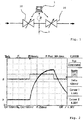
- FIG. 1 shows an overview of a device according to the invention for illustrating the method according to the invention.
- the valve 10 and the valve 20 Between the valve 10 and the valve 20 is an area with which a microchannel 2 is in pneumatic or hydraulic connection.
- the output of the system On the right side is indicated by an arrow the output of the system, which is connected to a pressure sink.
- the gas flow passes through the system from left to right.
- the device not restrictively indicated here as a computer, is set up to send control signals to the valves 10, 20.
- a pressure sensor is shown, which is set up to measure the pressure between the valves 10, 20 and forward it to the device.
- the pressure in the microchannel 2 is changed by means of actuation of the valves 10, 20 (eg for positioning of cells for microscopic observation).
- the valves change their respective valve opening degrees and, due to the ratio of the valve opening degrees, a certain pressure is established in the microchannel 2.
- For driving the device 1 sends control signals to both valves 10, 20, wherein the control signals for the one valve 10 are dependent on the control signals of the other valve 20 (and / or vice versa).
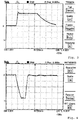
- FIG. 2 shows graphs of the time course of the control signal S and the pressure P in the micro-channel for driving the valve 10 (input valve) in the form of a rectangular pulse.
- the valve 20 output valve
- a pressure pulse with a very low pulse height and long pulse duration is shown.
- the pressure pulse With a short pilot current pulse to the high amplitude valve, the pressure pulse becomes steeper and shorter until a limit dynamic is reached, which is determined by the resistance of the valves, the applied pressures and the system volume.
- FIG. 3 shows the time course of the pressure P in the microchannel of a control according to the prior art, in which only one of the two valves is controlled and no negative pressure is connected to one of the valves. Shown is a typical pressure dynamics of a change from -200 to +200 mbar and again to - 200 mbar for a single-valve system with PID control. In addition to the lack of activation of the second valve, the missing negative pressure significantly worsens the dynamics, since the setpoint pressure 0 mbar is only approximated by an exponential curve, even when the second valve 20 is completely open. Also clearly visible are overshoots in response to a pulse.
- FIG. 4 shows the time course of the pressure P of a control according to the invention both valves 10, 20 wherein at one of the valves 10, 20, a positive pressure and at the other of the valves 10, 20, a negative pressure is connected. Both the pressure drop flank and the pressure rise flank are significantly steep and uniform in contrast to the previous figure.
- the second valve 20 which is connected to the pressure sink, fully opened, so that the pressure drop is maximum fast, kept open and then closed again.
- This control corresponds to a square pulse.
- the first valve 10 which is connected to the pressure source, fully opened, kept open and closed again, which corresponds to the driving in the form of a further rectangular pulse.
- the pulse height and / or the pulse duration are additionally varied during the control as a control variable for the regulation of the pressure in a PID control loop, so that the overshoots are significantly attenuated after reaching the setpoint.
- both flanks of the pressure change are maximally steeply generated.
- the connection of a negative pressure to the second valve 20 additionally amplifies this steepness. This achieves a linear and abrupt decrease. Furthermore, at the time when both valves are completely closed, no gas flow and thus a total gas flow only for a short time, whereby the gas consumption is reduced to the essentials.
- FIG. 5 shows a time course according to the invention of the control signals S1 for the first and S2 for the second valve and the resulting pressure curve P in the microchannel.
- the pressure should rise from one level to a higher level, then be lowered to a medium level.
- the first valve 10 is actuated at the pressure source by means of a pulse, as a result of which the first desired value is reached.
- the parameterization of the required control pulse S1 takes place via a predictive calculation based on the required pressure change.
- the valve 20 is opened to the atmosphere or to the low pressure input by means of another predictively calculated control pulse S2.
- the dependence between the control pulses of the valves is taken into account that always at least one valve has a minimum valve opening degree.
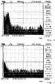
- FIG. 6 shows a course of the noise behavior of a method according to the invention with control of pressure pulses with set, fast dynamics of the control by control pulses.
- fast dynamics for example, after rapid changes in the target pressure, the noise caused by the control in the pressure signal is still relatively large: here about 20dB above the system's own noise by z.
- electronics thermal movement, semiconductors.
- the control noise is affected.
- the pulse heights are minimized and the pulse durations maximized.
- Fast dynamics with higher noise are set by larger pulse heights and shorter pulse durations.
- FIG. 7 shows a profile of the noise behavior of a method according to the invention with control of pressure pulses after a further short period of time.
- the pulse amplitudes are reduced after approaching the set point and thus the control noise is reduced. It is typically about 15dB above system noise.
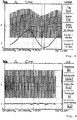
- FIG. 8 shows the dependence of the pressure pulses generated by the control pulses according to the invention of temperature fluctuations.
- the lower curve shows the modulation of the temperature by ⁇ 5 ° Kelvin for this illustration.
- the control voltage for the valve is always pulsed in the same way.
- the resulting pressure curve shows a clear dependence on the temperature profile and is therefore faulty.
- FIG. 9 shows the effect of a stabilization of the temperature according to the invention for controlling the pressure in the microchannel.
- the temperature curve is stabilized. Clearly visible is the constancy of the pressure changes without temperature-related fluctuation.
- the temperature is stabilized by commercially available temperature controllers and Peltier elements, which are placed on the valves.
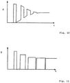
- FIG. 10 shows the transition from a pulsed operation to a continuous operation according to a first variant.
- the base level is raised in the case of leakage to the level of the control pulses S, so there is no difference. Thus, the pulses fall away and there is only a continuous control instead.
- the driving of the one valve is dependent on the driving of the other valve.
- FIG. 11 shows the transition from a pulsed operation in a continuous operation according to a second variant.
- the pulse height is lowered so far and thus the pulse width expanded so far that the control pulses S merge together.
- a continuous signal is obtained.
- system parameters can be measured, whereby further predictive control can be carried out by calculating pressure pulses required for a pressure change using one or more of these parameters.
Landscapes
- Chemical & Material Sciences (AREA)
- Health & Medical Sciences (AREA)
- Dispersion Chemistry (AREA)
- Analytical Chemistry (AREA)
- General Health & Medical Sciences (AREA)
- Hematology (AREA)
- Clinical Laboratory Science (AREA)
- Chemical Kinetics & Catalysis (AREA)
- Control Of Fluid Pressure (AREA)
Claims (14)
- Procédé de régulation de la pression dans un canal micro- ou mésofluidique (2) au moyen d'une première (10) et d'au moins une deuxième valve (20), dans lequel la première valve (10) présente un premier degré d'ouverture de valve réglable et l'au moins deuxième valve (20) présente un au moins deuxième degré d'ouverture de valve réglable, comprenant les étapes de :- commande de la première valve (10) pour le réglage du premier degré d'ouverture de valve,- commande de l'au moins deuxième valve (20) pour le réglage de l'au moins deuxième degré d'ouverture de valve,caractérisé en ce que
la commande d'une des valves (10, 20) se fait automatiquement et en fonction de la commande d'une autre des valves (10, 20),
dans lequel la dépendance de la commande de l'une des valves (10, 20) de la commande de l'autre des valves (10, 20) comporte un contre-couplage de la commande de l'une des valves (10, 20) et de la commande de l'autre des valves (10, 20),
autrement dit fermeture de l'une des valves et ouverture de l'autre des valves, lorsque la pression est trop élevée, ouverture de l'une des valves et fermeture de l'autre des valves, lorsque la pression est trop basse,
dans lequel la pression est régulée au moyen de la régulation PID ou PD ou de la régulation PI ou P et
un capteur de pression est conçu pour mesurer la pression entre les valves (10, 20),
dans lequel une surpression est raccordée à une des valves (10, 20) et une dépression est raccordée à l'autre des valves (10, 20),
dans lequel une zone, avec laquelle un canal micro- ou mésofluidique (2) est en communication pneumatique ou hydraulique, est entre l'une des valves (10) et l'autre des valves (20). - Procédé selon la revendication 1,
dans lequel le contre-couplage comporte comme condition un maintien constant de la somme d'une première résistance à l'écoulement de la première valve (10) et d'une deuxième résistance à l'écoulement de la deuxième valve (10). - Procédé selon l'une quelconque des revendications précédentes,
dans lequel un premier degré d'ouverture de valve minimale est défini ou sera défini pour la première valve (10) et un au moins deuxième degré d'ouverture de valve minimale est défini ou sera défini pour l'au moins deuxième valve (20) et la dépendance de la commande de l'une des valves (10, 20) de la commande de l'autre des valves (10, 20) comporte la condition que le degré d'ouverture de valve minimale respectif est toujours réglé pour au moins une des valves (10, 20) par la commande des valves (10, 20). - Procédé selon l'une quelconque des revendications précédentes,
dans lequel une évolution de préférence sans interruption de la pression dans le canal micro- ou mésofluidique (2) avec des valeurs de pression positives et négatives est réglée par la commande de la première valve (10) et la commande de l'au moins deuxième valve (20). - Procédé selon l'une quelconque des revendications précédentes,
dans lequel la commande d'au moins une des valves (10, 20) se fait sous la forme d'au moins une impulsion pour la génération d'au moins une impulsion de pression dans le canal micro- ou mésofluidique (2). - Procédé selon la revendication 5,
dans lequel le nombre de particules de gaz déplacées avec une des impulsions de pression générées dans le canal micro- ou mésofluidique (2) est déterminé et/ou le volume déplacé par une des impulsions de pression générées dans le canal micro- ou mésofluidique est déterminé et/ou le volume intérieur du canal micro- ou mésofluidique (2) est déterminé. - Procédé selon la revendication 5 à 6,
dans lequel l'au moins une impulsion présente une durée d'impulsion longue et/ou une amplitude d'impulsion élevée et/ou une grande valeur intégrale de courbe d'impulsion pour le positionnement grossier d'objets et/ou de fluides dans le canal micro- ou mésofluidique (2) et l'au moins une impulsion présente une durée d'impulsion plus courte et/ou une amplitude d'impulsion plus basse et/ou une petite valeur intégrale de courbe d'impulsion pour le positionnement fin. - Procédé selon la revendication 5 à 7,
dans lequel une grandeur de mesure est réglée dans le canal micro- ou mésofluidique (2), en particulier la pression, par commande répétée des valves (10, 20) sous forme de l'au moins une impulsion sur une valeur de consigne. - Procédé selon la revendication 8,
dans lequel il est régulé au moyen d'une régulation et une vitesse de réaction et/ou un bruit de régulation de la régulation est librement choisi et/ou adapté aux exigences des applications par un algorithme. - Procédé selon la revendication 5 à 9,
dans lequel une durée d'impulsion et une amplitude d'impulsion et/ou une valeur intégrale de courbe d'impulsion de l'au moins une impulsion sont déterminées en fonction d'une modification à obtenir de la pression dans le canal micro- ou mésofluidique (2). - Procédé selon la revendication 5 à 10,
dans lequel une pression d'entrée du canal micro- ou mésofluidique (2), qui s'applique à la première valve (10), est déterminée au moyen des étapes de :- commande de la première valve (10) sous forme de l'impulsion avec une première durée d'impulsion et une première amplitude d'impulsion et/ou avec une première valeur intégrale de courbe d'impulsion et commande de la deuxième valve (20) sous forme de l'impulsion avec une deuxième durée d'impulsion et une deuxième amplitude d'impulsion et/ou avec une deuxième valeur intégrale de courbe d'impulsion- mesure de la pression dans le canal micro- ou mésofluidique (2)- détermination de la pression d'entrée en fonction de la pression mesurée dans le canal micro- ou mésofluidique (2) et de la deuxième durée d'impulsion. - Procédé selon la revendication 5 à 11,
dans lequel il est passé de la commande d'au moins une des valves (10, 20) sous forme d'au moins une impulsion à un mode de fonctionnement sans impulsion ou il est passé du mode de fonctionnement sans impulsion à la commande d'au moins une des valves (10, 20) sous forme d'au moins une impulsion. - Procédé selon l'une quelconque des revendications précédentes, dans lequel une pression d'entrée dans le canal micro- et/ou mésofluidique (2) est réglée plus haute que la plage de pression souhaitée dans le canal micro- et/ou mésofluidique (2) et/ou une pression de sortie du canal micro- et/ou mésofluidique (2) est réglée plus basse que la plage de pression souhaitée dans le canal micro- et/ou mésofluidique (2).
- Dispositif (1) de régulation de la pression dans un canal micro- ou mésofluidique (2) au moyen d'une première (10) et d'au moins une deuxième valve (20), dans lequel la première valve (10) présente un premier degré d'ouverture de valve réglable et l'au moins deuxième valve (20) présente un au moins deuxième degré d'ouverture de valve réglable, dans lequel le dispositif (1) est conçu pour :- la commande de la première valve (10) pour le réglage du premier degré d'ouverture de valve,- la commande de l'au moins deuxième valve (20) pour le réglage de l'au moins deuxième degré d'ouverture de valve,caractérisé en ce que
le dispositif (1) est conçu en outre pour réaliser la commande d'une des valves (10, 20) automatiquement et en fonction de la commande d'une autre des valves (10, 20),
dans lequel la dépendance de la commande de l'une des valves (10, 20) de la commande de l'autre des valves (10, 20) comporte un contre-couplage de la commande de l'une des valves (10, 20) et de la commande de l'autre des valves (10, 20),
autrement dit fermeture de l'une des valves et ouverture de l'autre des valves, lorsque la pression est trop élevée, ouverture de l'une des valves et fermeture de l'autre des valves, lorsque la pression est trop basse,
dans lequel la pression est régulée au moyen de la régulation PID ou PD ou de la régulation PI ou P et
un capteur de pression est conçu pour mesurer la pression entre les valves (10, 20),
dans lequel une source de pression est raccordée à la première valve (10) et un puits de pression est raccordé à la deuxième valve (20),
dans lequel une zone, avec laquelle un canal micro- ou mésofluidique (2) est en communication pneumatique ou hydraulique, est entre l'une des valves (10) et l'autre des valves (20).
Applications Claiming Priority (1)
| Application Number | Priority Date | Filing Date | Title |
|---|---|---|---|
| DE102012019819.1A DE102012019819A1 (de) | 2012-10-10 | 2012-10-10 | Verfahren und eine Vorrichtung zur Steuerung des Drucks in einem Mikro- oder Mesofluidik-Kanal |
Publications (2)
| Publication Number | Publication Date |
|---|---|
| EP2719459A1 EP2719459A1 (fr) | 2014-04-16 |
| EP2719459B1 true EP2719459B1 (fr) | 2017-05-31 |
Family
ID=49385077
Family Applications (1)
| Application Number | Title | Priority Date | Filing Date |
|---|---|---|---|
| EP13004877.0A Active EP2719459B1 (fr) | 2012-10-10 | 2013-10-10 | Procédé et dispositif de commande de la pression dans un canal micro- ou mésofluidique |
Country Status (2)
| Country | Link |
|---|---|
| EP (1) | EP2719459B1 (fr) |
| DE (1) | DE102012019819A1 (fr) |
Families Citing this family (3)
| Publication number | Priority date | Publication date | Assignee | Title |
|---|---|---|---|---|
| CN114415746A (zh) * | 2021-11-29 | 2022-04-29 | 中国船舶工业集团公司第七0八研究所 | 新型级联微流体智能控制系统 |
| CN116329033A (zh) * | 2023-03-16 | 2023-06-27 | 苏州艾科瑞思智能装备股份有限公司 | 一种点胶器的自主胶量补偿方法 |
| CN118092192B (zh) * | 2024-04-23 | 2024-07-19 | 山东巧思智能科技有限公司 | 一种流体罐装参数优化控制方法及系统 |
Citations (6)
| Publication number | Priority date | Publication date | Assignee | Title |
|---|---|---|---|---|
| WO2001004909A1 (fr) | 1999-07-09 | 2001-01-18 | Orchid Biosciences, Inc. | Systeme de distribution de fluide dans un dispositif microfluidique grace a une impulsion de pression |
| WO2001088204A1 (fr) | 2000-05-15 | 2001-11-22 | Biomicro Systems, Inc. | Regulation de l'ecoulement d'air dans des circuits microfluidiques destinee au reglage de la pression et a l'echange de gaz |
| FR2855076B1 (fr) | 2003-05-21 | 2006-09-08 | Inst Curie | Dispositif microfluidique |
| US20080289710A1 (en) | 1999-06-28 | 2008-11-27 | California Institute Of Technology | Microfabricated elastomeric valve and pump systems |
| US20090320930A1 (en) | 2008-06-30 | 2009-12-31 | Canon U.S. Life Sciences, Inc. | System and method for microfluidic flow control |
| WO2010106428A2 (fr) | 2009-03-17 | 2010-09-23 | Silicon Biosystems S.P.A. | Système microfluidique |
-
2012
- 2012-10-10 DE DE102012019819.1A patent/DE102012019819A1/de not_active Withdrawn
-
2013
- 2013-10-10 EP EP13004877.0A patent/EP2719459B1/fr active Active
Patent Citations (6)
| Publication number | Priority date | Publication date | Assignee | Title |
|---|---|---|---|---|
| US20080289710A1 (en) | 1999-06-28 | 2008-11-27 | California Institute Of Technology | Microfabricated elastomeric valve and pump systems |
| WO2001004909A1 (fr) | 1999-07-09 | 2001-01-18 | Orchid Biosciences, Inc. | Systeme de distribution de fluide dans un dispositif microfluidique grace a une impulsion de pression |
| WO2001088204A1 (fr) | 2000-05-15 | 2001-11-22 | Biomicro Systems, Inc. | Regulation de l'ecoulement d'air dans des circuits microfluidiques destinee au reglage de la pression et a l'echange de gaz |
| FR2855076B1 (fr) | 2003-05-21 | 2006-09-08 | Inst Curie | Dispositif microfluidique |
| US20090320930A1 (en) | 2008-06-30 | 2009-12-31 | Canon U.S. Life Sciences, Inc. | System and method for microfluidic flow control |
| WO2010106428A2 (fr) | 2009-03-17 | 2010-09-23 | Silicon Biosystems S.P.A. | Système microfluidique |
Non-Patent Citations (10)
| Title |
|---|
| A GUIDE TO PULSE WIDTH MODULATED FLOW CONTROL, 2007 |
| ANONYMOUS: "LabView TM, System Identification Toolkit User Manual", NATIONAL INSTRUMENTS, August 2006 (2006-08-01), pages v - B-1, XP055476260 |
| ANONYMOUS: "microfluidic ChipShop, Lab-on-a-Chip Catalogue", MICROFLUIDIC CHIPSHOP, July 2010 (2010-07-01), pages 1 - 62, XP055476235 |
| ANONYMOUS: "MicroFluidics Control System", FLUIGENT, 2008, pages 1 - 39, XP055476221 |
| ANONYMOUS: "PID Theory Explained", NATIONAL INSTRUMENTS, 29 March 2011 (2011-03-29), XP055476219 |
| ANONYMOUS: "Proportional Pressure Regulating Valve-AIRFIT TECNO-Hoerbiger.com", 2006, XP055476317, Retrieved from the Internet <URL:http://www.njetc.com/previous-website/tecno-e.html> |
| BONG ET AL.: "Compressed-air flow control system", LAB ON A CHIP, vol. 11, no. 4, 29 November 2010 (2010-11-29), pages 743 - 747, XP055205620 |
| HOERBIGER ORIGA: "Data sheet N°. 5.96.002E-1", PRESSURE REGULATING VALVE G1/8, NW 2.5 |
| MARK, D. ET AL.: "Aliquoting on the centrifugal microfluidic platform based on centrifugo-pneumatic valves", MICROFLUID NANOFLUID, vol. 10, 2011, pages 1279 - 1288, XP019902430, Retrieved from the Internet <URL:10.1007/s10404-010-0759-0> |
| WITTENMARK ET AL.: "On Self Tuning Regulators", 1 January 1972 (1972-01-01), pages 1-35,185 - 199, XP055476286 |
Also Published As
| Publication number | Publication date |
|---|---|
| EP2719459A1 (fr) | 2014-04-16 |
| DE102012019819A1 (de) | 2014-04-10 |
Similar Documents
| Publication | Publication Date | Title |
|---|---|---|
| EP2212086B2 (fr) | Procédé et dispositif pour surveiller, documenter et/ou réguler une presse d'injection | |
| EP1270073B1 (fr) | Système microfluidique avec régulateur | |
| EP2874039B1 (fr) | Procédé de commande pour un système de transmission de chaleur et système de transmission de chaleur de ce type | |
| EP3663001B1 (fr) | Methode de pipetage pourvu de point d'étranglement dans le canal de pipetage | |
| EP2719459B1 (fr) | Procédé et dispositif de commande de la pression dans un canal micro- ou mésofluidique | |
| EP2998029B1 (fr) | Procede d'application automatique d'un milieu liquide ou visqueux sur des composants et dispositif de dosage destine a executer le procede | |
| EP3176667B1 (fr) | Unite de precommande, agencement de soupape et procede de preparation reglee d'un fluide | |
| EP2633914B1 (fr) | Dispositif de pipetage et son procédé de fabrication | |
| EP2527061A1 (fr) | Procédé de refroidissement d'un faisceau métallique et vanne de commande pour l'ouverture et la fermeture intermittentes d'un flux volumique d'un fluide de refroidissement | |
| DE102013209866B4 (de) | Vorrichtung mit vorgegebener Fluidverdrängung | |
| EP4234205A2 (fr) | Dispositif d'extrusion et procédé pour influencer l'épaisseur de paroi d'un profilé en plastique extrudé | |
| DE19953075A1 (de) | Stellgliedsteuerschaltkreis | |
| WO2016005145A1 (fr) | Dispositif de chauffage d'une couche fonctionnelle | |
| EP3424679B1 (fr) | Dispositif filtrant et son procédé de fonctionnement | |
| WO2017054019A1 (fr) | Procédé et dispositif pour déterminer les propriétés à basse température | |
| DE102018221365A1 (de) | Verfahren zum Abtragen von Material von einem Werkstück und Laserbearbeitungsanlage | |
| WO2018060230A1 (fr) | Dispositif de régulation avec ajustabilité du comportement de régulation | |
| EP2966936A1 (fr) | Dispositif de chauffage d'une couche fonctionnelle | |
| DE2803770C2 (de) | Vorrichtung zur Regelung der Temperatur einer im Kreislauf geführten Flüssigkeit auf einem Prüfstand | |
| EP3580529A1 (fr) | Procédé et dispositif de mise en place d'une ligne de remplissage sur un récipient | |
| WO2006018006A1 (fr) | Procedes pour filtrer un fluide et dispositif et unite de filtrage pour mettre en oeuvre lesdits procedes | |
| DE102004027161B3 (de) | Ventileinrichtung | |
| DE2644919C2 (de) | Vorrichtung zur Regelung der Temperatur eines Wärmeübertragers | |
| DE102016200173A1 (de) | Vorrichtung zur Erwärmung einer Funktionsschicht | |
| EP3626976A1 (fr) | Convertisseur électrique-pneumatique, utilisation d'un convertisseur électrique-pneumatique, régulateur de positionnement et appareil de commande |
Legal Events
| Date | Code | Title | Description |
|---|---|---|---|
| PUAI | Public reference made under article 153(3) epc to a published international application that has entered the european phase |
Free format text: ORIGINAL CODE: 0009012 |
|
| AK | Designated contracting states |
Kind code of ref document: A1 Designated state(s): AL AT BE BG CH CY CZ DE DK EE ES FI FR GB GR HR HU IE IS IT LI LT LU LV MC MK MT NL NO PL PT RO RS SE SI SK SM TR |
|
| AX | Request for extension of the european patent |
Extension state: BA ME |
|
| 17P | Request for examination filed |
Effective date: 20141016 |
|
| RBV | Designated contracting states (corrected) |
Designated state(s): AL AT BE BG CH CY CZ DE DK EE ES FI FR GB GR HR HU IE IS IT LI LT LU LV MC MK MT NL NO PL PT RO RS SE SI SK SM TR |
|
| 17Q | First examination report despatched |
Effective date: 20160112 |
|
| GRAP | Despatch of communication of intention to grant a patent |
Free format text: ORIGINAL CODE: EPIDOSNIGR1 |
|
| STAA | Information on the status of an ep patent application or granted ep patent |
Free format text: STATUS: GRANT OF PATENT IS INTENDED |
|
| RAP1 | Party data changed (applicant data changed or rights of an application transferred) |
Owner name: FUETTERER, CLAUS |
|
| RIN1 | Information on inventor provided before grant (corrected) |
Inventor name: FUETTERER, CLAUS |
|
| INTG | Intention to grant announced |
Effective date: 20161223 |
|
| GRAS | Grant fee paid |
Free format text: ORIGINAL CODE: EPIDOSNIGR3 |
|
| GRAA | (expected) grant |
Free format text: ORIGINAL CODE: 0009210 |
|
| STAA | Information on the status of an ep patent application or granted ep patent |
Free format text: STATUS: THE PATENT HAS BEEN GRANTED |
|
| AK | Designated contracting states |
Kind code of ref document: B1 Designated state(s): AL AT BE BG CH CY CZ DE DK EE ES FI FR GB GR HR HU IE IS IT LI LT LU LV MC MK MT NL NO PL PT RO RS SE SI SK SM TR |
|
| REG | Reference to a national code |
Ref country code: CH Ref legal event code: EP Ref country code: GB Ref legal event code: FG4D Free format text: NOT ENGLISH |
|
| REG | Reference to a national code |
Ref country code: AT Ref legal event code: REF Ref document number: 896948 Country of ref document: AT Kind code of ref document: T Effective date: 20170615 |
|
| REG | Reference to a national code |
Ref country code: IE Ref legal event code: FG4D Free format text: LANGUAGE OF EP DOCUMENT: GERMAN |
|
| REG | Reference to a national code |
Ref country code: DE Ref legal event code: R096 Ref document number: 502013007346 Country of ref document: DE |
|
| REG | Reference to a national code |
Ref country code: CH Ref legal event code: NV Representative=s name: SCHMAUDER AND PARTNER AG PATENT- UND MARKENANW, CH |
|
| REG | Reference to a national code |
Ref country code: NL Ref legal event code: MP Effective date: 20170531 |
|
| REG | Reference to a national code |
Ref country code: LT Ref legal event code: MG4D |
|
| REG | Reference to a national code |
Ref country code: FR Ref legal event code: PLFP Year of fee payment: 5 |
|
| PG25 | Lapsed in a contracting state [announced via postgrant information from national office to epo] |
Ref country code: FI Free format text: LAPSE BECAUSE OF FAILURE TO SUBMIT A TRANSLATION OF THE DESCRIPTION OR TO PAY THE FEE WITHIN THE PRESCRIBED TIME-LIMIT Effective date: 20170531 Ref country code: NO Free format text: LAPSE BECAUSE OF FAILURE TO SUBMIT A TRANSLATION OF THE DESCRIPTION OR TO PAY THE FEE WITHIN THE PRESCRIBED TIME-LIMIT Effective date: 20170831 Ref country code: ES Free format text: LAPSE BECAUSE OF FAILURE TO SUBMIT A TRANSLATION OF THE DESCRIPTION OR TO PAY THE FEE WITHIN THE PRESCRIBED TIME-LIMIT Effective date: 20170531 Ref country code: LT Free format text: LAPSE BECAUSE OF FAILURE TO SUBMIT A TRANSLATION OF THE DESCRIPTION OR TO PAY THE FEE WITHIN THE PRESCRIBED TIME-LIMIT Effective date: 20170531 Ref country code: HR Free format text: LAPSE BECAUSE OF FAILURE TO SUBMIT A TRANSLATION OF THE DESCRIPTION OR TO PAY THE FEE WITHIN THE PRESCRIBED TIME-LIMIT Effective date: 20170531 Ref country code: GR Free format text: LAPSE BECAUSE OF FAILURE TO SUBMIT A TRANSLATION OF THE DESCRIPTION OR TO PAY THE FEE WITHIN THE PRESCRIBED TIME-LIMIT Effective date: 20170901 |
|
| PG25 | Lapsed in a contracting state [announced via postgrant information from national office to epo] |
Ref country code: LV Free format text: LAPSE BECAUSE OF FAILURE TO SUBMIT A TRANSLATION OF THE DESCRIPTION OR TO PAY THE FEE WITHIN THE PRESCRIBED TIME-LIMIT Effective date: 20170531 Ref country code: IS Free format text: LAPSE BECAUSE OF FAILURE TO SUBMIT A TRANSLATION OF THE DESCRIPTION OR TO PAY THE FEE WITHIN THE PRESCRIBED TIME-LIMIT Effective date: 20170930 Ref country code: RS Free format text: LAPSE BECAUSE OF FAILURE TO SUBMIT A TRANSLATION OF THE DESCRIPTION OR TO PAY THE FEE WITHIN THE PRESCRIBED TIME-LIMIT Effective date: 20170531 Ref country code: SE Free format text: LAPSE BECAUSE OF FAILURE TO SUBMIT A TRANSLATION OF THE DESCRIPTION OR TO PAY THE FEE WITHIN THE PRESCRIBED TIME-LIMIT Effective date: 20170531 Ref country code: BG Free format text: LAPSE BECAUSE OF FAILURE TO SUBMIT A TRANSLATION OF THE DESCRIPTION OR TO PAY THE FEE WITHIN THE PRESCRIBED TIME-LIMIT Effective date: 20170831 Ref country code: NL Free format text: LAPSE BECAUSE OF FAILURE TO SUBMIT A TRANSLATION OF THE DESCRIPTION OR TO PAY THE FEE WITHIN THE PRESCRIBED TIME-LIMIT Effective date: 20170531 |
|
| PG25 | Lapsed in a contracting state [announced via postgrant information from national office to epo] |
Ref country code: RO Free format text: LAPSE BECAUSE OF FAILURE TO SUBMIT A TRANSLATION OF THE DESCRIPTION OR TO PAY THE FEE WITHIN THE PRESCRIBED TIME-LIMIT Effective date: 20170531 Ref country code: EE Free format text: LAPSE BECAUSE OF FAILURE TO SUBMIT A TRANSLATION OF THE DESCRIPTION OR TO PAY THE FEE WITHIN THE PRESCRIBED TIME-LIMIT Effective date: 20170531 Ref country code: SK Free format text: LAPSE BECAUSE OF FAILURE TO SUBMIT A TRANSLATION OF THE DESCRIPTION OR TO PAY THE FEE WITHIN THE PRESCRIBED TIME-LIMIT Effective date: 20170531 Ref country code: DK Free format text: LAPSE BECAUSE OF FAILURE TO SUBMIT A TRANSLATION OF THE DESCRIPTION OR TO PAY THE FEE WITHIN THE PRESCRIBED TIME-LIMIT Effective date: 20170531 Ref country code: CZ Free format text: LAPSE BECAUSE OF FAILURE TO SUBMIT A TRANSLATION OF THE DESCRIPTION OR TO PAY THE FEE WITHIN THE PRESCRIBED TIME-LIMIT Effective date: 20170531 |
|
| PG25 | Lapsed in a contracting state [announced via postgrant information from national office to epo] |
Ref country code: PL Free format text: LAPSE BECAUSE OF FAILURE TO SUBMIT A TRANSLATION OF THE DESCRIPTION OR TO PAY THE FEE WITHIN THE PRESCRIBED TIME-LIMIT Effective date: 20170531 Ref country code: SM Free format text: LAPSE BECAUSE OF FAILURE TO SUBMIT A TRANSLATION OF THE DESCRIPTION OR TO PAY THE FEE WITHIN THE PRESCRIBED TIME-LIMIT Effective date: 20170531 Ref country code: IT Free format text: LAPSE BECAUSE OF FAILURE TO SUBMIT A TRANSLATION OF THE DESCRIPTION OR TO PAY THE FEE WITHIN THE PRESCRIBED TIME-LIMIT Effective date: 20170531 |
|
| PGFP | Annual fee paid to national office [announced via postgrant information from national office to epo] |
Ref country code: GB Payment date: 20171024 Year of fee payment: 5 |
|
| REG | Reference to a national code |
Ref country code: DE Ref legal event code: R026 Ref document number: 502013007346 Country of ref document: DE |
|
| PLBI | Opposition filed |
Free format text: ORIGINAL CODE: 0009260 |
|
| PLAX | Notice of opposition and request to file observation + time limit sent |
Free format text: ORIGINAL CODE: EPIDOSNOBS2 |
|
| 26 | Opposition filed |
Opponent name: FLUIGENT Effective date: 20180228 |
|
| PG25 | Lapsed in a contracting state [announced via postgrant information from national office to epo] |
Ref country code: MC Free format text: LAPSE BECAUSE OF FAILURE TO SUBMIT A TRANSLATION OF THE DESCRIPTION OR TO PAY THE FEE WITHIN THE PRESCRIBED TIME-LIMIT Effective date: 20170531 Ref country code: SI Free format text: LAPSE BECAUSE OF FAILURE TO SUBMIT A TRANSLATION OF THE DESCRIPTION OR TO PAY THE FEE WITHIN THE PRESCRIBED TIME-LIMIT Effective date: 20170531 |
|
| PLBB | Reply of patent proprietor to notice(s) of opposition received |
Free format text: ORIGINAL CODE: EPIDOSNOBS3 |
|
| REG | Reference to a national code |
Ref country code: IE Ref legal event code: MM4A |
|
| PG25 | Lapsed in a contracting state [announced via postgrant information from national office to epo] |
Ref country code: LU Free format text: LAPSE BECAUSE OF NON-PAYMENT OF DUE FEES Effective date: 20171010 |
|
| REG | Reference to a national code |
Ref country code: BE Ref legal event code: MM Effective date: 20171031 |
|
| PG25 | Lapsed in a contracting state [announced via postgrant information from national office to epo] |
Ref country code: BE Free format text: LAPSE BECAUSE OF NON-PAYMENT OF DUE FEES Effective date: 20171031 |
|
| REG | Reference to a national code |
Ref country code: CH Ref legal event code: PK Free format text: BERICHTIGUNGEN |
|
| RAP2 | Party data changed (patent owner data changed or rights of a patent transferred) |
Owner name: BPT WEITERBILDUNG UG |
|
| RIN2 | Information on inventor provided after grant (corrected) |
Inventor name: FUETTERER, CLAUS |
|
| REG | Reference to a national code |
Ref country code: DE Ref legal event code: R082 Ref document number: 502013007346 Country of ref document: DE Representative=s name: MAIKOWSKI & NINNEMANN PATENTANWAELTE PARTNERSC, DE Ref country code: DE Ref legal event code: R081 Ref document number: 502013007346 Country of ref document: DE Owner name: BPT WEITERBILDUNG UG (HAFTUNGSBESCHRAENKT), DE Free format text: FORMER OWNER: FUETTERER, CLAUS, PROF. DR., 04317 LEIPZIG, DE |
|
| PG25 | Lapsed in a contracting state [announced via postgrant information from national office to epo] |
Ref country code: MT Free format text: LAPSE BECAUSE OF FAILURE TO SUBMIT A TRANSLATION OF THE DESCRIPTION OR TO PAY THE FEE WITHIN THE PRESCRIBED TIME-LIMIT Effective date: 20170531 |
|
| REG | Reference to a national code |
Ref country code: FR Ref legal event code: PLFP Year of fee payment: 6 |
|
| PG25 | Lapsed in a contracting state [announced via postgrant information from national office to epo] |
Ref country code: IE Free format text: LAPSE BECAUSE OF NON-PAYMENT OF DUE FEES Effective date: 20171010 |
|
| GBPC | Gb: european patent ceased through non-payment of renewal fee |
Effective date: 20181010 |
|
| PG25 | Lapsed in a contracting state [announced via postgrant information from national office to epo] |
Ref country code: HU Free format text: LAPSE BECAUSE OF FAILURE TO SUBMIT A TRANSLATION OF THE DESCRIPTION OR TO PAY THE FEE WITHIN THE PRESCRIBED TIME-LIMIT; INVALID AB INITIO Effective date: 20131010 |
|
| PLCK | Communication despatched that opposition was rejected |
Free format text: ORIGINAL CODE: EPIDOSNREJ1 |
|
| APBM | Appeal reference recorded |
Free format text: ORIGINAL CODE: EPIDOSNREFNO |
|
| APBP | Date of receipt of notice of appeal recorded |
Free format text: ORIGINAL CODE: EPIDOSNNOA2O |
|
| APAH | Appeal reference modified |
Free format text: ORIGINAL CODE: EPIDOSCREFNO |
|
| PLAB | Opposition data, opponent's data or that of the opponent's representative modified |
Free format text: ORIGINAL CODE: 0009299OPPO |
|
| PG25 | Lapsed in a contracting state [announced via postgrant information from national office to epo] |
Ref country code: CY Free format text: LAPSE BECAUSE OF NON-PAYMENT OF DUE FEES Effective date: 20170531 Ref country code: GB Free format text: LAPSE BECAUSE OF NON-PAYMENT OF DUE FEES Effective date: 20181010 |
|
| PLAB | Opposition data, opponent's data or that of the opponent's representative modified |
Free format text: ORIGINAL CODE: 0009299OPPO |
|
| PLAB | Opposition data, opponent's data or that of the opponent's representative modified |
Free format text: ORIGINAL CODE: 0009299OPPO |
|
| R26 | Opposition filed (corrected) |
Opponent name: FLUIGENT Effective date: 20180228 |
|
| PG25 | Lapsed in a contracting state [announced via postgrant information from national office to epo] |
Ref country code: MK Free format text: LAPSE BECAUSE OF FAILURE TO SUBMIT A TRANSLATION OF THE DESCRIPTION OR TO PAY THE FEE WITHIN THE PRESCRIBED TIME-LIMIT Effective date: 20170531 |
|
| R26 | Opposition filed (corrected) |
Opponent name: FLUIGENT Effective date: 20180228 |
|
| REG | Reference to a national code |
Ref country code: DE Ref legal event code: R100 Ref document number: 502013007346 Country of ref document: DE |
|
| REG | Reference to a national code |
Ref country code: AT Ref legal event code: MM01 Ref document number: 896948 Country of ref document: AT Kind code of ref document: T Effective date: 20181010 |
|
| APBU | Appeal procedure closed |
Free format text: ORIGINAL CODE: EPIDOSNNOA9O |
|
| R26 | Opposition filed (corrected) |
Opponent name: FLUIGENT Effective date: 20180228 |
|
| PLBN | Opposition rejected |
Free format text: ORIGINAL CODE: 0009273 |
|
| PLBP | Opposition withdrawn |
Free format text: ORIGINAL CODE: 0009264 |
|
| STAA | Information on the status of an ep patent application or granted ep patent |
Free format text: STATUS: OPPOSITION REJECTED |
|
| PG25 | Lapsed in a contracting state [announced via postgrant information from national office to epo] |
Ref country code: AT Free format text: LAPSE BECAUSE OF NON-PAYMENT OF DUE FEES Effective date: 20181010 |
|
| 27O | Opposition rejected |
Effective date: 20191213 |
|
| PG25 | Lapsed in a contracting state [announced via postgrant information from national office to epo] |
Ref country code: TR Free format text: LAPSE BECAUSE OF FAILURE TO SUBMIT A TRANSLATION OF THE DESCRIPTION OR TO PAY THE FEE WITHIN THE PRESCRIBED TIME-LIMIT Effective date: 20170531 |
|
| PG25 | Lapsed in a contracting state [announced via postgrant information from national office to epo] |
Ref country code: PT Free format text: LAPSE BECAUSE OF FAILURE TO SUBMIT A TRANSLATION OF THE DESCRIPTION OR TO PAY THE FEE WITHIN THE PRESCRIBED TIME-LIMIT Effective date: 20170531 |
|
| PG25 | Lapsed in a contracting state [announced via postgrant information from national office to epo] |
Ref country code: AL Free format text: LAPSE BECAUSE OF FAILURE TO SUBMIT A TRANSLATION OF THE DESCRIPTION OR TO PAY THE FEE WITHIN THE PRESCRIBED TIME-LIMIT Effective date: 20170531 |
|
| REG | Reference to a national code |
Ref country code: DE Ref legal event code: R084 Ref document number: 502013007346 Country of ref document: DE |
|
| REG | Reference to a national code |
Ref country code: DE Ref legal event code: R081 Ref document number: 502013007346 Country of ref document: DE Owner name: BIOPHYSICAL TOOLS GMBH, DE Free format text: FORMER OWNER: BPT WEITERBILDUNG UG (HAFTUNGSBESCHRAENKT), 04317 LEIPZIG, DE |
|
| REG | Reference to a national code |
Ref country code: CH Ref legal event code: U11 Free format text: ST27 STATUS EVENT CODE: U-0-0-U10-U11 (AS PROVIDED BY THE NATIONAL OFFICE) Effective date: 20251101 |
|
| PGFP | Annual fee paid to national office [announced via postgrant information from national office to epo] |
Ref country code: DE Payment date: 20251021 Year of fee payment: 13 |
|
| PGFP | Annual fee paid to national office [announced via postgrant information from national office to epo] |
Ref country code: FR Payment date: 20251024 Year of fee payment: 13 |
|
| PGFP | Annual fee paid to national office [announced via postgrant information from national office to epo] |
Ref country code: CH Payment date: 20251101 Year of fee payment: 13 |