EP2719565A1 - Vorbaustruktur für ein Nutzkraftfahrzeug - Google Patents
Vorbaustruktur für ein Nutzkraftfahrzeug Download PDFInfo
- Publication number
- EP2719565A1 EP2719565A1 EP13183353.5A EP13183353A EP2719565A1 EP 2719565 A1 EP2719565 A1 EP 2719565A1 EP 13183353 A EP13183353 A EP 13183353A EP 2719565 A1 EP2719565 A1 EP 2719565A1
- Authority
- EP
- European Patent Office
- Prior art keywords
- cross member
- structure according
- side members
- frame side
- members
- Prior art date
- Legal status (The legal status is an assumption and is not a legal conclusion. Google has not performed a legal analysis and makes no representation as to the accuracy of the status listed.)
- Granted
Links
Images


Classifications
-
- B—PERFORMING OPERATIONS; TRANSPORTING
- B60—VEHICLES IN GENERAL
- B60K—ARRANGEMENT OR MOUNTING OF PROPULSION UNITS OR OF TRANSMISSIONS IN VEHICLES; ARRANGEMENT OR MOUNTING OF PLURAL DIVERSE PRIME-MOVERS IN VEHICLES; AUXILIARY DRIVES FOR VEHICLES; INSTRUMENTATION OR DASHBOARDS FOR VEHICLES; ARRANGEMENTS IN CONNECTION WITH COOLING, AIR INTAKE, GAS EXHAUST OR FUEL SUPPLY OF PROPULSION UNITS IN VEHICLES
- B60K11/00—Arrangement in connection with cooling of propulsion units
- B60K11/02—Arrangement in connection with cooling of propulsion units with liquid cooling
- B60K11/04—Arrangement or mounting of radiators, radiator shutters, or radiator blinds
-
- B—PERFORMING OPERATIONS; TRANSPORTING
- B60—VEHICLES IN GENERAL
- B60R—VEHICLES, VEHICLE FITTINGS, OR VEHICLE PARTS, NOT OTHERWISE PROVIDED FOR
- B60R19/00—Wheel guards; Radiator guards, e.g. grilles; Obstruction removers; Fittings damping bouncing force in collisions
- B60R19/02—Bumpers, i.e. impact receiving or absorbing members for protecting vehicles or fending off blows from other vehicles or objects
- B60R19/04—Bumpers, i.e. impact receiving or absorbing members for protecting vehicles or fending off blows from other vehicles or objects formed from more than one section in a side-by-side arrangement
- B60R19/12—Bumpers, i.e. impact receiving or absorbing members for protecting vehicles or fending off blows from other vehicles or objects formed from more than one section in a side-by-side arrangement vertically spaced
-
- B—PERFORMING OPERATIONS; TRANSPORTING
- B62—LAND VEHICLES FOR TRAVELLING OTHERWISE THAN ON RAILS
- B62D—MOTOR VEHICLES; TRAILERS
- B62D21/00—Understructures, i.e. chassis frame on which a vehicle body may be mounted
- B62D21/15—Understructures, i.e. chassis frame on which a vehicle body may be mounted having impact absorbing means, e.g. a frame designed to permanently or temporarily change shape or dimension upon impact with another body
- B62D21/152—Front or rear frames
-
- B—PERFORMING OPERATIONS; TRANSPORTING
- B62—LAND VEHICLES FOR TRAVELLING OTHERWISE THAN ON RAILS
- B62D—MOTOR VEHICLES; TRAILERS
- B62D25/00—Superstructure or monocoque structure sub-units; Parts or details thereof not otherwise provided for
- B62D25/08—Front or rear portions
- B62D25/082—Engine compartments
- B62D25/084—Radiator supports
-
- B—PERFORMING OPERATIONS; TRANSPORTING
- B62—LAND VEHICLES FOR TRAVELLING OTHERWISE THAN ON RAILS
- B62D—MOTOR VEHICLES; TRAILERS
- B62D25/00—Superstructure or monocoque structure sub-units; Parts or details thereof not otherwise provided for
- B62D25/08—Front or rear portions
- B62D25/082—Engine compartments
- B62D25/085—Front-end modules
Definitions
- the present invention relates to a front-end structure for a utility vehicle according to the preamble of patent claim 1.
- a stem structure of the generic type describes, for example, the DE 10 2004 038 487 A1 in which, inter alia, a bumper cross member and including an underrun protection cross member are connected to a mounting unit, which also carry a positioned behind the bumper crossmember radiator module. Since the two cross members lie essentially in a uniform vertical transverse plane, the radiator module sits close behind the cross members due to the design, so it is exposed to increased damage, for example in a frontal crash. Furthermore, the cross members, which are each pulled to the lateral vehicle outer contour, cover front surface areas which would possibly be useful as air inflow openings for radiator modules.
- the object of the invention is to provide a structurally and production engineering favorable stem structure, which allows in addition to sufficient deformation paths in a frontal crash advantageous arrangements of cooler modules.
- the underrun protection cross member is seen to the bumper cross member seen in side view offset by a dimension a to the front vehicle outer contour to the rear and carries the radiator module. This makes it possible to move the radiator module relatively away from the bumper cross member and to provide deformation in a crash that initially protects the radiator module against damage and / or to gain additional installation space.
- the bumper cross member may end substantially at the frame longitudinal members and be connected via deformation elements with these, wherein the cooler module is positioned in a lying behind the deformation elements vertical transverse plane.
- the underrun protection crossmember can laterally be brought up the bumper cross member up to the wheel track of the front wheels of the utility vehicle and additionally carry on one side or on both sides outside of the frame side member located Radhaus cooling modules. These cooling modules are not covered by the shorter designed bumper cross member and can thus be effectively flowed over the front intake grille with airstream.
- the dimension a or the resetting of the underrun protection cross member can be approx. 400 mm, whereby the lower edge of the underrun protection cross member is adjusted to ⁇ 400 mm to the roadway. In the context of legal requirements, this ensures a structurally favorable construction with a given slope angle at the front of the vehicle.
- the underrun protection crossmember can be connected via a plurality of vertical struts and lower side members to the longitudinal frame members and thus ensure in a very rigid construction an advantageous in the event of a crash force introduction into the frame side members of the utility vehicle.
- the vertical struts can be formed directly on the partition plates of the deformation elements directly from the production engineering point of view and easy to assemble, or can form a structural unit with them.
- the front apron of the commercial vehicle forming the front outer contour can be particularly preferably connected to the cross members, among others, wherein the underside rising obliquely forward with the lower edge of the underride guard cross member substantially defines the slope angle in a line.
- the bumper cross member with the deformation elements, the underrun protection cross member with the vertical struts and the longitudinal members and the radiator modules form a pre-assembly, which can be attached, inter alia, to the frame rails.
- the Fig. 1 shows partially a front structure 1 for commercial vehicles with two extending to both sides of the frame side members 2, to which in a higher position, a bumper cross member 3 and in an underlying position, an underrun protection cross member 4 are connected.
- radiator module 5 With, for example, a heat exchanger 5a and a condenser 5b arranged an air conditioning, extending to the lower underrun protection cross member 4 extends and is supported by this, among others, only indicated fastening means 6.
- Upper attachment means for example, to front or side body components are not shown and may be of known type.
- Radhaus cooler modules 7, the - as from Fig. 1 it can be seen - are also aligned vertically and are not covered by the end of the frame longitudinal members 2 bumper cross member 3 or by ventilation grille (not shown) in the front apron of the utility vehicle from the front are freely streamable.
- the cooler modules 7 are in turn fastened by means of fastening means 6 on the underrun protection cross member 4 and above on suitable bodywork side parts, wheel arch panels, etc.
- the Fig. 2 shows the front structure 1 without cooler modules 5 and 7.
- the bumper cross member 3 which may be made in a known manner from a steel profile sheet, connected via the deformation elements 8 and a sheet-metal bulkhead 9 to the end faces of the frame rails 2 firmly screwed to these (not shown).
- the underride protection cross member 4 also consisting of a steel profile sheet is connected directly via two vertical struts 10 to the partition plates 9 (molded or welded).
- two longitudinal members 11, whose stiffness or configuration is designed to be weaker than the frame side members 2 are fastened to the cross member 4, which extend substantially below the frame side members 2 and initially parallel thereto and then attached to non-illustrated, downwardly projecting portions of the frame side members 2 or screwed to them (or vice versa).
- the bumper cross member 3 with the deformation elements 8 and the bulkhead plates 9 and the underrun protection cross member 4 with the vertical struts 10 and the longitudinal members 11 form a mounting unit which is optionally attachable to the frame side members 2 with the already mounted cooler modules 5 and 7.
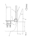
- the side view Fig. 3 shows simplified the configuration of the front structure 1 and the arrangement of the cross member 3 and 4 to each other and compared by a front apron (not shown) formed front outer contour 12 and the underfloor contour 13 of the utility vehicle.
- the underride protection cross member 4 is offset by a dimension a of about 400 mm to the outer contour 12 and about half the value to the bumper cross member 3 to the rear, creating a greater deformation in a frontal crash is created, which increases the cooler modules 5 and 7 protects.
- the distance of the underride guard cross member 4 to a horizontal road surface 14 is about 400 mm, resulting in the drawn ground clearance (underbody contour 13) and the slope angle ⁇ (forward rising line 15 along the contours 12 and 13 and through the vertical center of the wheel Front wheels) defined.
- only one cooler module 7 can be provided on only one side of the vehicle.
- the reinforcements 10 and 11 of the underride guard cross member 4 may also be used in any number other than described.
Landscapes
- Engineering & Computer Science (AREA)
- Mechanical Engineering (AREA)
- Chemical & Material Sciences (AREA)
- Combustion & Propulsion (AREA)
- Transportation (AREA)
- Body Structure For Vehicles (AREA)
Abstract
Description
- Die vorliegende Erfindung betrifft eine Vorbaustruktur für ein Nutzkraftfahrzeug gemäß dem Oberbegriff des Patentanspruchs 1.
- Eine Vorbaustruktur der gattungsgemäßen Art beschreibt zum Beispiel die
DE 10 2004 038 487 A1 , bei der unter anderem ein Stoßfängerquerträger und darunter ein Unterfahrschutz-Querträger zu einer Montageeinheit verbunden sind, die zudem ein hinter dem StoßfängerQuerträger positioniertes Kühlermodul tragen. Da die beiden Querträger im Wesentlichen in einer einheitlichen Vertikalquerebene liegen, sitzt bauartbedingt das Kühlermodul dicht hinter den Querträgern, ist also zum Beispiel bei einem Frontalcrash vermehrt Beschädigungen ausgesetzt. Ferner decken die jeweils bis zur seitlichen Fahrzeugaußenkontur gezogenen Querträger frontseitige Flächenbereiche ab, die gegebenenfalls als Lufteinströmöffnungen für Kühlermodule nützlich wären. - Aufgabe der Erfindung ist es, eine baulich und fertigungstechnisch günstige Vorbaustruktur zu schaffen, die neben ausreichenden Verformungswegen bei einem Frontalcrash vorteilhafte Anordnungen von Kühlermodulen ermöglicht.
- Die Lösung dieser Aufgabe ist den Merkmalen des Patentanspruchs 1 entnehmbar. Vorteilhafte und besonders zweckmäßige Weiterbildungen der Erfindung sind Gegenstand der Unteransprüche.
- Erfindungsgemäß wird vorgeschlagen, dass der Unterfahrschutz-Querträger zum Stoßfängerquerträger in Seitenansicht gesehen um ein Maß a zur vorderen Fahrzeugaußenkontur nach hinten versetzt ist und das Kühlermodul trägt. Damit gelingt es, das Kühlermodul relativ vom Stoßfängerquerträger abzurücken und Verformungsweg bei einem Crash zu schaffen, der das Kühlermodul zunächst vor Beschädigung schützt und/oder einen zusätzlichen Einbauraum zu gewinnen.
- Insbesondere kann der Stoßfängerquerträger im Wesentlichen bei den Rahmenlängsträgern enden und über Deformationselemente mit diesen verbunden sein, wobei das Kühlermodul in einer hinter den Deformationselementen liegenden Vertikalquerebene positioniert ist.
- In vorteilhafter Weiterbildung der Erfindung kann der Unterfahrschutz-Querträger seitlich den Stoßfängerquerträger überragend bis zur Radspur der Vorderräder des Nutzkraftfahrzeugs herangeführt sein und zusätzlich einseitig oder beidseitig außerhalb der Rahmenlängsträger befindliche Radhaus-Kühlmodule tragen. Diese Kühlmodule sind von dem kürzer ausgeführten Stoßfängerquerträger nicht überdeckt und können somit über frontseitige Einströmgitter wirksam mit Fahrtwind angeströmt werden.
- Das Maß a bzw. das Zurücksetzen des Unterfahrschutz-Querträgers kann ca. 400 mm betragen, wobei die Unterkante des Unterfahrschutz-Querträgers auf < 400 mm zur Fahrbahn eingestellt ist. Dies stellt im Rahmen gesetzlicher Vorgaben eine baulich günstige Konstruktion mit einem vorgegebenen Böschungswinkel an der Fahrzeugvorderseite sicher.
- In einer baulich besonders zweckmäßigen Ausgestaltung der Erfindung kann der Unterfahrschutz-Querträger über mehrere Vertikalstreben und über untere Längsträger an die Rahmenlängsträger angebunden sein und somit bei einer sehr steifen Konstruktion eine im Crashfall vorteilhafte Krafteinleitung in die Rahmenlängsträger des Nutzkraftfahrzeugs sicherstellen.
- Dabei können fertigungstechnisch günstig und montageeinfach die Vertikalstreben an die Schottbleche der Deformationselemente unmittelbar angeformt sein oder mit diesen eine Baueinheit bilden. Zudem können die unteren, eine geringere Steifigkeit als die Rahmenlängsträger aufweisenden Längsträger unterhalb der Rahmenlängsträger verlaufend mit diesen lösbar verbunden, insbesondere verschraubt sein.
- Die die vordere Außenkontur bildende Frontschürze des Nutzkraftfahrzeugs kann besonders bevorzugt unter anderem an die Querträger angebunden sein, wobei der schräg nach vorne ansteigende Unterboden mit der Unterkante des Unterfahrschutz-Querträgers im Wesentlichen in einer Linie den Böschungswinkel definiert.
- Schließlich können der Stoßfänger-Querträger mit den Deformationselementen, der Unterfahrschutz-Querträger mit den Vertikalstreben und den Längsträgern und die Kühlermodule eine Vormontageeinheit bilden, die unter anderem an die Rahmenlängsträger anbaubar ist.
- Die vorstehend erläuterten und/oder in den Unteransprüchen wiedergegebenen vorteilhaften Aus- und/oder Weiterbildungen der Erfindung können - außer zum Beispiel in den Fällen eindeutiger Abhängigkeiten oder unvereinbarer Alternativen - einzeln oder aber auch in beliebiger Kombination miteinander zur Anwendung kommen.
- Die Erfindung und ihre vorteilhaften Aus- und Weiterbildungen sowie deren Vorteile werden nachfolgend anhand von Zeichnungen näher erläutert.
- Es zeigen:
- Fig. 1
- eine Vorbaustruktur für ein Nutzfahrzeug mit einem an die seitlichen Rahmenlängsträger angeschlossenen Stoßfängerquerträger, einem Unterfahrschutz-Querträger und mehreren Kühlermodulen;
- Fig. 2
- in vereinfachter Darstellung die Vorbaustruktur nach
Fig. 1 ohne Kühlermodule; und - Fig. 3
- eine Seitenansicht der
Fig. 2 der Vorbaustruktur mit Darstellung des Maßes a und des Böschungswinkels α. - Die
Fig. 1 zeigt teilweise eine Vorbaustruktur 1 für Nutzkraftfahrzeuge mit zwei zu beiden Seiten verlaufenden Rahmenlängsträgern 2, an die in einer höheren Position ein Stoßfängerquerträger 3 und in einer darunter liegenden Position ein Unterfahrschutz-Querträger 4 angeschlossen sind. - In Fahrtrichtung des Nutzkraftfahrzeugs betrachtet hinter dem Stoßfängerquerträger 3 bzw. dessen Deformationselemente 8 und zwischen den Rahmenlängsträgern 2 ist ein etwa vertikal ausgerichtetes Kühlermodul 5 mit zum Beispiel einem Wärmetauscher 5a und einem Kondensator 5b einer Klimaanlage angeordnet, das sich bis zu dem unten liegenden Unterfahrschutz-Querträger 4 erstreckt und unter anderem von diesem über nur angedeutete Befestigungsmittel 6 getragen ist. Obere Befestigungsmittel zum Beispiel an vorderen oder seitlichen Karosseriebauteilen sind nicht dargestellt und können bekannter Bauart sein.
- Ferner trägt der seitlich nach außen bis zu den Radspuren der Vorderräder des Nutzfahrzeugs geführte Unterfahrschutz-Querträger 4 beidseitig außerhalb der Rahmenlängsträger 2 befindliche Radhaus-Kühlermodule 7, die - wie aus
Fig. 1 ersichtlich ist - ebenfalls vertikal ausgerichtet sind und von dem an den Rahmenlängsträgern 2 endenden Stoßfängerquerträger 3 nicht überdeckt sind bzw. durch Lüftungsgitter (nicht dargestellt) in der Frontschürze des Nutzkraftfahrzeugs von vorne frei anströmbar sind. Die Kühlermodule 7 sind wiederum mittels Befestigungsmittel 6 am Unterfahrschutz-Querträger 4 und oberhalb an geeigneten Karosserieseitenteilen, Radhausblechen, etc. befestigt. - Die
Fig. 2 zeigt die Vorbaustruktur 1 ohne Kühlermodule 5 und 7. Wie ersichtlich ist, ist der Stoßfängerquerträger 3, der in bekannter Weise aus einem Stahl-Profilblech gefertigt sein kann, über die Deformationselemente 8 und ein flächiges Schottblech 9 an die Stirnseiten der Rahmenlängsträger 2 angeschlossen bzw. fest mit diesen verschraubt (nicht dargestellt). - Der Unterfahrschutz-Querträger 4 ebenfalls aus einem Stahlprofilblech bestehend ist unmittelbar über zwei Vertikalstreben 10 an die Schottbleche 9 angebunden (angeformt oder angeschweißt).
- Des Weiteren sind an dem Querträger 4 zwei in ihrer Steifigkeit bzw. Konfiguration schwächer als die Rahmenlängsträger 2 ausgeführte Längsträger 11 befestigt, die im Wesentlichen unterhalb der Rahmenlängsträger 2 und zunächst parallel dazu verlaufen und dann an nicht dargestellten, nach unten ragenden Abschnitten der Rahmenlängsträger 2 befestigt bzw. mit diesen verschraubt sind (oder umgekehrt).
- Durch die dargestellte Konstruktion bilden der Stoßfängerquerträger 3 mit den Deformationselementen 8 und den Schottblechen 9 sowie der Unterfahrschutz-Querträger 4 mit den Vertikalstreben 10 und den Längsträgern 11 eine Montageeinheit, die gegebenenfalls mit den bereits angebauten Kühlermodulen 5 und 7 an die Rahmenlängsträger 2 anbaubar ist.
- Die Seitenansicht
Fig. 3 zeigt vereinfacht die Konfiguration der Vorbaustruktur 1 bzw. die Anordnung der Querträger 3 und 4 zueinander und im Vergleich der durch eine Frontschürze (nicht dargestellt) gebildeten, vorderen Außenkontur 12 und der Unterbodenkontur 13 des Nutzkraftfahrzeugs. - Dabei ist der Unterfahrschutz-Querträger 4 um ein Maß a von ca. 400 mm zur Außenkontur 12 und ca. um den halben Wert zum Stoßfängerquerträger 3 nach hinten versetzt, wodurch ein größerer Verformungsweg bei einem Frontalcrash geschaffen ist, der die Kühlermodule 5 und 7 vermehrt schützt.
- Ferner beträgt der Abstand des Unterfahrschutz-Querträgers 4 zu einer horizontalen Fahrbahnebene 14 ca. 400 mm, woraus sich die eingezeichnete Bodenfreiheit (Unterbodenkontur 13) und der Böschungswinkel α (nach vorne ansteigende Linie 15 entlang der Konturen 12 und 13 und durch die senkrechte Radmitte der Vorderräder) definiert.
- Die Erfindung ist nicht auf das dargestellte Ausführungsbeispiel beschränkt. Im Rahmen der Patentansprüche sind dem Fachmann geläufige Abwandlungen zum Beispiel aufgrund konstruktiver Gegebenheiten durchaus möglich.
- So kann gegebenenfalls nur ein Kühlermodul 7 auf nur einer Fahrzeugseite vorgesehen sein. Die Verstärkungen 10 und 11 des Unterfahrschutz-Querträgers 4 können gegebenenfallsauch in einer anderen Anzahl als beschrieben verwendet sein.
-
- 1
- Vorbaustruktur
- 2
- Rahmenlängsträger
- 3
- Stoßfängerquerträger
- 4
- Unterfahrschutz-Querträger
- 5
- Kühlermodul
- 5a
- Wärmetauscher
- 5b
- Kondensator
- 6
- Befestigungsmittel
- 7
- Kühlermodule
- 8
- Deformationselemente
- 9
- Schottbleche
- 10
- Vertikalstreben
- 11
- Längsträger
- 12
- Vordere Außenkontur
- 13
- Unterbodenkontur
- 14
- Fahrbahn
- 15
- Linie Böschungswinkel
Claims (9)
- Vorbaustruktur für ein Nutzkraftfahrzeug, mit seitlichen Rahmenlängsträgern (2), einem Stoßfängerquerträger (3) und einem darunter angeordneten, als Unterfahrschutz dienenden Querträger (4), wobei die Querträger (4) zugleich ein hinter dem Stoßfängerquerträger (3) und zwischen den Rahmenlängsträgern (2) angeordnetes Kühlermodul (5) tragen, dadurch gekennzeichnet, dass der Unterfahrschutz-Querträger (4) zum Stoßfängerquerträger (3) in Seitenansicht gesehen um einen Längsversatz (a) zur Fahrzeugaußenkontur (12) nach hinten versetzt ist und insbesondere das Kühlermodul (5, 7) trägt.
- Vorbaustruktur nach Anspruch 1, dadurch gekennzeichnet, dass der Stoßfängerquerträger (3) im Wesentlichen bei den Rahmenlängsträgern (2) endet und über Deformationselemente (8) mit diesen verbunden ist, wobei das Kühlermodul (5, 7) in einer hinter den Deformationselementen (8) liegenden Vertikalquerebene positioniert ist.
- Vorbaustruktur nach Anspruch 1 oder 2, dadurch gekennzeichnet, dass der Unterfahrschutz-Querträger (4) seitlich den Stoßfängerquerträger (3) überragend bis zur Radspur der Vorderräder des Nutzkraftfahrzeugs herangeführt ist und zusätzlich einseitig oder beidseitig außerhalb der Rahmenlängsträger (2) befindliche Kühlermodule (7) trägt.
- Vorbaustruktur nach Anspruch 1, 2 oder 3, dadurch gekennzeichnet, dass der Längsversatz (a) maximal 400 mm oder kleiner ist und/oder dass die Unterkante des Unterfahrschutz-Querträgers (4) um einen Höhenversatz (b) von der Fahrbahn (14) beabstandet ist, der maximal 400 mm oder kleiner ist.
- Vorbaustruktur nach einem der vorhergehenden Ansprüche, dadurch gekennzeichnet, dass der Unterfahrschutz-Querträger (4) über mehrere Vertikalstreben (10) und über untere Längsträger (11) an die Rahmenlängsträger (2) mittelbar oder unmittelbar angebunden ist.
- Vorbaustruktur nach Anspruch 5, dadurch gekennzeichnet, dass die Vertikalstreben (10) an die Schottbleche (9) der Deformationselemente (8) angeformt sind oder mit diesen eine Baueinheit bilden.
- Vorbaustruktur nach Anspruch 5 oder 6, dadurch gekennzeichnet, dass die unteren, eine geringere Steifigkeit als die Rahmenlängsträger (2) aufweisenden Längsträger (11) unterhalb der Rahmenlängsträger (2) verlaufend mit diesen lösbar verbunden, insbesondere verschraubt sind.
- Vorbaustruktur nach einem der vorhergehenden Ansprüche, dadurch gekennzeichnet, dass die die Außenkontur (12) bildende Frontschürze des Nutzkraftfahrzeugs unter anderem an die Querträger (3, 4) angebunden ist, wobei der schräg nach vorne ansteigende Unterboden (13) mit der Unterkante des Unterfahrschutz-Querträgers (4) den Böschungswinkel oc definiert.
- Vorbaustruktur nach einem der vorhergehenden Ansprüche, dadurch gekennzeichnet, dass der Stoßfänger-Querträger (3) mit den Deformationselementen (8), der Unterfahrschutz-Querträger (4) mit den Vertikalstreben (10) und den Längsträgern (11) und die Kühlermodule (5, 7) eine Vormontageeinheit bilden, die unter anderem an die Rahmenlängsträger (2) anbaubar ist.
Applications Claiming Priority (1)
| Application Number | Priority Date | Filing Date | Title |
|---|---|---|---|
| DE102012019933.3A DE102012019933A1 (de) | 2012-10-11 | 2012-10-11 | Vorbaustruktur für ein Nutzkraftfahrzeug |
Publications (2)
| Publication Number | Publication Date |
|---|---|
| EP2719565A1 true EP2719565A1 (de) | 2014-04-16 |
| EP2719565B1 EP2719565B1 (de) | 2017-07-19 |
Family
ID=49150770
Family Applications (1)
| Application Number | Title | Priority Date | Filing Date |
|---|---|---|---|
| EP13183353.5A Active EP2719565B1 (de) | 2012-10-11 | 2013-09-06 | Vorbaustruktur für ein Nutzkraftfahrzeug |
Country Status (2)
| Country | Link |
|---|---|
| EP (1) | EP2719565B1 (de) |
| DE (1) | DE102012019933A1 (de) |
Cited By (6)
| Publication number | Priority date | Publication date | Assignee | Title |
|---|---|---|---|---|
| WO2016207038A3 (de) * | 2015-06-23 | 2017-02-23 | Bayerische Motoren Werke Aktiengesellschaft | Abstützeinrichtung für einen vorderwagen eines personenkraftfahrzeugs |
| WO2017133888A1 (de) * | 2016-02-05 | 2017-08-10 | Bayerische Motoren Werke Aktiengesellschaft | Kraftfahrzeug |
| WO2021244911A1 (de) | 2020-06-03 | 2021-12-09 | Man Truck & Bus Se | Vorbaustruktur für ein nutzfahrzeug, vorzugsweise für einen lastkraftwagen |
| CN113859366A (zh) * | 2021-10-29 | 2021-12-31 | 岚图汽车科技有限公司 | 一种通用化前端模块、机舱总成及汽车 |
| CN114096440A (zh) * | 2019-07-19 | 2022-02-25 | 沃尔沃卡车集团 | 用于重型车辆的前部防钻撞装置 |
| US11407883B2 (en) | 2020-02-03 | 2022-08-09 | Illinois Tool Works Inc. | High performing low viscosity tire sealant |
Families Citing this family (5)
| Publication number | Priority date | Publication date | Assignee | Title |
|---|---|---|---|---|
| DE102014220703B4 (de) | 2014-10-13 | 2021-01-21 | Volkswagen Aktiengesellschaft | Anordnung im Bereich eines Montageträgers im Vorderwagen eines Kraftfahrzeuges |
| CN107472006A (zh) * | 2017-06-28 | 2017-12-15 | 奇瑞汽车股份有限公司 | 一种插电式混合动力汽车前舱的布置型式 |
| DE102018222171B3 (de) | 2018-12-18 | 2020-06-18 | Volkswagen Aktiengesellschaft | Anordnung einer Schutzstruktur für einen Montageträger in einem Vorderwagen eines Kraftfahrzeuges |
| DE102021102366B4 (de) | 2021-02-02 | 2024-04-18 | Benteler Automobiltechnik Gmbh | Stoßfängeranordnung für ein Kraftfahrzeug |
| DE102021119754A1 (de) | 2021-07-29 | 2023-02-02 | Bayerische Motoren Werke Aktiengesellschaft | Fahrzeug mit Fahrzeugfrontaufbau mit Verbindungsstruktur zwischen Querträgern |
Citations (6)
| Publication number | Priority date | Publication date | Assignee | Title |
|---|---|---|---|---|
| DE10051567A1 (de) * | 1999-10-20 | 2001-04-26 | Denso Corp | Vordere Fahrzeug-Endstruktur |
| EP1232931A1 (de) * | 2001-02-19 | 2002-08-21 | Mazda Motor Corporation | Vordere Fahrzeug-Endstruktur |
| DE102004014073A1 (de) * | 2004-03-23 | 2005-10-27 | Hbpo Gmbh | Frontend mit Montageträger |
| DE102004038487A1 (de) | 2004-08-07 | 2006-03-16 | Man Nutzfahrzeuge Ag | Fahrgestell für ein Nutzfahrzeug |
| DE102005058180A1 (de) * | 2005-12-05 | 2007-06-06 | Peguform Gmbh | Frontendmodul für ein Kraftfahrzeug mit einer energieabsorbierenden Schutzfunktion für ein Kühlmodul |
| DE102009058287A1 (de) * | 2009-12-14 | 2011-06-16 | GM Global Technology Operations LLC, ( n. d. Ges. d. Staates Delaware ), Detroit | Vorderbau für ein Kraftfahrzeug |
Family Cites Families (8)
| Publication number | Priority date | Publication date | Assignee | Title |
|---|---|---|---|---|
| JP2002274430A (ja) * | 2001-03-15 | 2002-09-25 | Fuji Heavy Ind Ltd | 車体の前部構造 |
| DE10112424A1 (de) * | 2001-03-15 | 2002-09-26 | Daimler Chrysler Ag | Kraftwagenbug mit einer Stoßfängereinheit |
| DE10247420B3 (de) * | 2002-10-11 | 2004-04-15 | Daimlerchrysler Ag | Kombirahmen |
| JP2005219531A (ja) * | 2004-02-03 | 2005-08-18 | Denso Corp | 車両用熱交換器冷却装置 |
| DE102004028161B4 (de) * | 2004-06-09 | 2018-07-12 | Volkswagen Ag | Unterfahrschutz für Personenkraftfahrzeuge zur Anordnung unter Längsträgerniveau vor einem Hilfsrahmen oder Achsträger als zusätzliche Crashebene |
| DE102007050191A1 (de) * | 2007-10-20 | 2009-04-23 | Daimler Ag | Frontbereich für einen Kraftwagen |
| DE102008048039A1 (de) * | 2008-09-19 | 2010-03-25 | Volkswagen Ag | Frontend an einem Fahrzeug, insbesondere Kraftfahrzeug |
| DE102009004154A1 (de) * | 2009-01-09 | 2010-07-15 | Man Nutzfahrzeuge Ag | Verfahren zum Aufbau eines Vorderwagens eines Lastkraftwagens mit Fahrerhaus und Vorderwagen eines Lastwagens |
-
2012
- 2012-10-11 DE DE102012019933.3A patent/DE102012019933A1/de not_active Withdrawn
-
2013
- 2013-09-06 EP EP13183353.5A patent/EP2719565B1/de active Active
Patent Citations (6)
| Publication number | Priority date | Publication date | Assignee | Title |
|---|---|---|---|---|
| DE10051567A1 (de) * | 1999-10-20 | 2001-04-26 | Denso Corp | Vordere Fahrzeug-Endstruktur |
| EP1232931A1 (de) * | 2001-02-19 | 2002-08-21 | Mazda Motor Corporation | Vordere Fahrzeug-Endstruktur |
| DE102004014073A1 (de) * | 2004-03-23 | 2005-10-27 | Hbpo Gmbh | Frontend mit Montageträger |
| DE102004038487A1 (de) | 2004-08-07 | 2006-03-16 | Man Nutzfahrzeuge Ag | Fahrgestell für ein Nutzfahrzeug |
| DE102005058180A1 (de) * | 2005-12-05 | 2007-06-06 | Peguform Gmbh | Frontendmodul für ein Kraftfahrzeug mit einer energieabsorbierenden Schutzfunktion für ein Kühlmodul |
| DE102009058287A1 (de) * | 2009-12-14 | 2011-06-16 | GM Global Technology Operations LLC, ( n. d. Ges. d. Staates Delaware ), Detroit | Vorderbau für ein Kraftfahrzeug |
Cited By (15)
| Publication number | Priority date | Publication date | Assignee | Title |
|---|---|---|---|---|
| WO2016207038A3 (de) * | 2015-06-23 | 2017-02-23 | Bayerische Motoren Werke Aktiengesellschaft | Abstützeinrichtung für einen vorderwagen eines personenkraftfahrzeugs |
| CN107074296A (zh) * | 2015-06-23 | 2017-08-18 | 宝马股份公司 | 用于轿车的前厢的支撑装置 |
| US10035546B2 (en) | 2015-06-23 | 2018-07-31 | Bayerische Motoren Werke Aktiengesellschaft | Support device for a front end of a passenger motor vehicle |
| CN107074296B (zh) * | 2015-06-23 | 2019-08-20 | 宝马股份公司 | 用于轿车的前厢的支撑装置和轿车 |
| WO2017133888A1 (de) * | 2016-02-05 | 2017-08-10 | Bayerische Motoren Werke Aktiengesellschaft | Kraftfahrzeug |
| US10752217B2 (en) | 2016-02-05 | 2020-08-25 | Bayerische Motoren Werke Aktiengesellschaft | Motor vehicle |
| CN114096440A (zh) * | 2019-07-19 | 2022-02-25 | 沃尔沃卡车集团 | 用于重型车辆的前部防钻撞装置 |
| US12257968B2 (en) | 2019-07-19 | 2025-03-25 | Volvo Truck Corporation | Front underrun protection device for a heavy vehicle |
| US11407883B2 (en) | 2020-02-03 | 2022-08-09 | Illinois Tool Works Inc. | High performing low viscosity tire sealant |
| DE102020114756A1 (de) | 2020-06-03 | 2021-12-09 | Man Truck & Bus Se | Vorbaustruktur für ein Nutzfahrzeug, vorzugsweise für einen Lastkraftwagen |
| WO2021244911A1 (de) | 2020-06-03 | 2021-12-09 | Man Truck & Bus Se | Vorbaustruktur für ein nutzfahrzeug, vorzugsweise für einen lastkraftwagen |
| US20230286587A1 (en) * | 2020-06-03 | 2023-09-14 | Man Truck & Bus Se | Front structure for a utility vehicle, preferably for a lorry |
| US12377917B2 (en) | 2020-06-03 | 2025-08-05 | Man Truck & Bus Se | Front structure for a utility vehicle, preferably for a lorry |
| EP4733111A2 (de) | 2020-06-03 | 2026-04-29 | MAN Truck & Bus SE | Vorbaustruktur für ein nutzfahrzeug, vorzugsweise für einen lastkraftwagen |
| CN113859366A (zh) * | 2021-10-29 | 2021-12-31 | 岚图汽车科技有限公司 | 一种通用化前端模块、机舱总成及汽车 |
Also Published As
| Publication number | Publication date |
|---|---|
| DE102012019933A1 (de) | 2014-04-17 |
| EP2719565B1 (de) | 2017-07-19 |
Similar Documents
| Publication | Publication Date | Title |
|---|---|---|
| EP2719565B1 (de) | Vorbaustruktur für ein Nutzkraftfahrzeug | |
| EP2766247B1 (de) | Aufbaustruktur für ein elektrisch angetriebenes personen-kraftfahrzeug | |
| EP2014501B1 (de) | Frontendmodul für Fahrzeuge | |
| DE102015112506A1 (de) | Frontendmodul | |
| DE102009012057B4 (de) | Vorrichtung zum Aufnehmen von Seitenkräften und Kraftfahrzeug mit einer derartigen Vorrichtung | |
| DE102012006527A1 (de) | Bodenstruktur einer Kraftfahrzeugkarosserie | |
| DE102010035367A1 (de) | Crashenergieabsorbierende Anordnung für ein Kraftfahrzeug mit Hybridantrieb oder Elektromaschine | |
| DE102007053171B4 (de) | Motorhaube für ein Kraftfahrzeug | |
| DE202014002086U1 (de) | Bodenstruktur einer Kraftfahrzeugkarosserie in Leichtbauweise | |
| DE102009050495A1 (de) | Hilfsrahmen | |
| EP1754650B1 (de) | Frontendmodul mit einem Montageträger mit unterem Querträger | |
| DE102004007571B4 (de) | Vorderwagen für ein Fahrzeug, insbesondere für ein Kraftfahrzeug | |
| EP2128000A1 (de) | Radkraftfahrzeug und Fahrzeugtragstruktur hierfür | |
| EP2399782B1 (de) | Traggestell zur seitlichen Befestigung von Anbauteilen an einem Längsträger einer Nutzfahrzeug-Tragstruktur | |
| DE102004050435B4 (de) | Stoßfängersystem für Kraftfahrzeug | |
| EP1554170A1 (de) | Seitenwandmodul eines kraftfahrzeuges | |
| DE102011121906A1 (de) | Bodenstruktur einer Kraftfahrzeugkarosserie | |
| DE102010013382A1 (de) | Stoßfängeranordnung für ein Kraftfahrzeug | |
| DE102010055445A1 (de) | Karosserievorderbau eines Kraftfahrzeugs | |
| DE976897C (de) | Wagenkasten fuer Kraftwagen und aehnliche Fahrzeuge | |
| DE102017200113A1 (de) | Stoßfängerquerträger für ein Kraftfahrzeug sowie Kraftfahrzeug mit einem solchen Stoßfängerquerträger | |
| EP1592586A1 (de) | Frontendbereich | |
| DE102004063741A1 (de) | Vorderwagen für ein Fahrzeug, insbesondere für ein Kraftfahrzeug | |
| DE102011018488A1 (de) | Vorbaustruktur für ein Kraftfahrzeug | |
| DE102009012941A1 (de) | Sicherheitsvorrichtung am Bug der Karosserie von Personenkraftfahrzeugen |
Legal Events
| Date | Code | Title | Description |
|---|---|---|---|
| PUAI | Public reference made under article 153(3) epc to a published international application that has entered the european phase |
Free format text: ORIGINAL CODE: 0009012 |
|
| AK | Designated contracting states |
Kind code of ref document: A1 Designated state(s): AL AT BE BG CH CY CZ DE DK EE ES FI FR GB GR HR HU IE IS IT LI LT LU LV MC MK MT NL NO PL PT RO RS SE SI SK SM TR |
|
| AX | Request for extension of the european patent |
Extension state: BA ME |
|
| 17P | Request for examination filed |
Effective date: 20141016 |
|
| RBV | Designated contracting states (corrected) |
Designated state(s): AL AT BE BG CH CY CZ DE DK EE ES FI FR GB GR HR HU IE IS IT LI LT LU LV MC MK MT NL NO PL PT RO RS SE SI SK SM TR |
|
| GRAP | Despatch of communication of intention to grant a patent |
Free format text: ORIGINAL CODE: EPIDOSNIGR1 |
|
| GRAJ | Information related to disapproval of communication of intention to grant by the applicant or resumption of examination proceedings by the epo deleted |
Free format text: ORIGINAL CODE: EPIDOSDIGR1 |
|
| GRAP | Despatch of communication of intention to grant a patent |
Free format text: ORIGINAL CODE: EPIDOSNIGR1 |
|
| INTG | Intention to grant announced |
Effective date: 20170127 |
|
| INTG | Intention to grant announced |
Effective date: 20170207 |
|
| GRAS | Grant fee paid |
Free format text: ORIGINAL CODE: EPIDOSNIGR3 |
|
| GRAA | (expected) grant |
Free format text: ORIGINAL CODE: 0009210 |
|
| AK | Designated contracting states |
Kind code of ref document: B1 Designated state(s): AL AT BE BG CH CY CZ DE DK EE ES FI FR GB GR HR HU IE IS IT LI LT LU LV MC MK MT NL NO PL PT RO RS SE SI SK SM TR |
|
| REG | Reference to a national code |
Ref country code: GB Ref legal event code: FG4D Free format text: NOT ENGLISH |
|
| REG | Reference to a national code |
Ref country code: CH Ref legal event code: EP |
|
| REG | Reference to a national code |
Ref country code: IE Ref legal event code: FG4D Free format text: LANGUAGE OF EP DOCUMENT: GERMAN |
|
| REG | Reference to a national code |
Ref country code: AT Ref legal event code: REF Ref document number: 910024 Country of ref document: AT Kind code of ref document: T Effective date: 20170815 |
|
| REG | Reference to a national code |
Ref country code: DE Ref legal event code: R096 Ref document number: 502013007793 Country of ref document: DE |
|
| REG | Reference to a national code |
Ref country code: FR Ref legal event code: PLFP Year of fee payment: 5 |
|
| REG | Reference to a national code |
Ref country code: NL Ref legal event code: MP Effective date: 20170719 |
|
| REG | Reference to a national code |
Ref country code: LT Ref legal event code: MG4D |
|
| PG25 | Lapsed in a contracting state [announced via postgrant information from national office to epo] |
Ref country code: HR Free format text: LAPSE BECAUSE OF FAILURE TO SUBMIT A TRANSLATION OF THE DESCRIPTION OR TO PAY THE FEE WITHIN THE PRESCRIBED TIME-LIMIT Effective date: 20170719 Ref country code: NO Free format text: LAPSE BECAUSE OF FAILURE TO SUBMIT A TRANSLATION OF THE DESCRIPTION OR TO PAY THE FEE WITHIN THE PRESCRIBED TIME-LIMIT Effective date: 20171019 Ref country code: SE Free format text: LAPSE BECAUSE OF FAILURE TO SUBMIT A TRANSLATION OF THE DESCRIPTION OR TO PAY THE FEE WITHIN THE PRESCRIBED TIME-LIMIT Effective date: 20170719 Ref country code: LT Free format text: LAPSE BECAUSE OF FAILURE TO SUBMIT A TRANSLATION OF THE DESCRIPTION OR TO PAY THE FEE WITHIN THE PRESCRIBED TIME-LIMIT Effective date: 20170719 Ref country code: FI Free format text: LAPSE BECAUSE OF FAILURE TO SUBMIT A TRANSLATION OF THE DESCRIPTION OR TO PAY THE FEE WITHIN THE PRESCRIBED TIME-LIMIT Effective date: 20170719 Ref country code: NL Free format text: LAPSE BECAUSE OF FAILURE TO SUBMIT A TRANSLATION OF THE DESCRIPTION OR TO PAY THE FEE WITHIN THE PRESCRIBED TIME-LIMIT Effective date: 20170719 |
|
| PG25 | Lapsed in a contracting state [announced via postgrant information from national office to epo] |
Ref country code: IS Free format text: LAPSE BECAUSE OF FAILURE TO SUBMIT A TRANSLATION OF THE DESCRIPTION OR TO PAY THE FEE WITHIN THE PRESCRIBED TIME-LIMIT Effective date: 20171119 Ref country code: GR Free format text: LAPSE BECAUSE OF FAILURE TO SUBMIT A TRANSLATION OF THE DESCRIPTION OR TO PAY THE FEE WITHIN THE PRESCRIBED TIME-LIMIT Effective date: 20171020 Ref country code: LV Free format text: LAPSE BECAUSE OF FAILURE TO SUBMIT A TRANSLATION OF THE DESCRIPTION OR TO PAY THE FEE WITHIN THE PRESCRIBED TIME-LIMIT Effective date: 20170719 Ref country code: RS Free format text: LAPSE BECAUSE OF FAILURE TO SUBMIT A TRANSLATION OF THE DESCRIPTION OR TO PAY THE FEE WITHIN THE PRESCRIBED TIME-LIMIT Effective date: 20170719 Ref country code: ES Free format text: LAPSE BECAUSE OF FAILURE TO SUBMIT A TRANSLATION OF THE DESCRIPTION OR TO PAY THE FEE WITHIN THE PRESCRIBED TIME-LIMIT Effective date: 20170719 Ref country code: BG Free format text: LAPSE BECAUSE OF FAILURE TO SUBMIT A TRANSLATION OF THE DESCRIPTION OR TO PAY THE FEE WITHIN THE PRESCRIBED TIME-LIMIT Effective date: 20171019 Ref country code: PL Free format text: LAPSE BECAUSE OF FAILURE TO SUBMIT A TRANSLATION OF THE DESCRIPTION OR TO PAY THE FEE WITHIN THE PRESCRIBED TIME-LIMIT Effective date: 20170719 |
|
| REG | Reference to a national code |
Ref country code: DE Ref legal event code: R097 Ref document number: 502013007793 Country of ref document: DE |
|
| PG25 | Lapsed in a contracting state [announced via postgrant information from national office to epo] |
Ref country code: RO Free format text: LAPSE BECAUSE OF FAILURE TO SUBMIT A TRANSLATION OF THE DESCRIPTION OR TO PAY THE FEE WITHIN THE PRESCRIBED TIME-LIMIT Effective date: 20170719 Ref country code: CZ Free format text: LAPSE BECAUSE OF FAILURE TO SUBMIT A TRANSLATION OF THE DESCRIPTION OR TO PAY THE FEE WITHIN THE PRESCRIBED TIME-LIMIT Effective date: 20170719 Ref country code: DK Free format text: LAPSE BECAUSE OF FAILURE TO SUBMIT A TRANSLATION OF THE DESCRIPTION OR TO PAY THE FEE WITHIN THE PRESCRIBED TIME-LIMIT Effective date: 20170719 |
|
| REG | Reference to a national code |
Ref country code: CH Ref legal event code: PL |
|
| PLBE | No opposition filed within time limit |
Free format text: ORIGINAL CODE: 0009261 |
|
| STAA | Information on the status of an ep patent application or granted ep patent |
Free format text: STATUS: NO OPPOSITION FILED WITHIN TIME LIMIT |
|
| PG25 | Lapsed in a contracting state [announced via postgrant information from national office to epo] |
Ref country code: SM Free format text: LAPSE BECAUSE OF FAILURE TO SUBMIT A TRANSLATION OF THE DESCRIPTION OR TO PAY THE FEE WITHIN THE PRESCRIBED TIME-LIMIT Effective date: 20170719 Ref country code: IT Free format text: LAPSE BECAUSE OF FAILURE TO SUBMIT A TRANSLATION OF THE DESCRIPTION OR TO PAY THE FEE WITHIN THE PRESCRIBED TIME-LIMIT Effective date: 20170719 Ref country code: EE Free format text: LAPSE BECAUSE OF FAILURE TO SUBMIT A TRANSLATION OF THE DESCRIPTION OR TO PAY THE FEE WITHIN THE PRESCRIBED TIME-LIMIT Effective date: 20170719 Ref country code: MC Free format text: LAPSE BECAUSE OF FAILURE TO SUBMIT A TRANSLATION OF THE DESCRIPTION OR TO PAY THE FEE WITHIN THE PRESCRIBED TIME-LIMIT Effective date: 20170719 Ref country code: SK Free format text: LAPSE BECAUSE OF FAILURE TO SUBMIT A TRANSLATION OF THE DESCRIPTION OR TO PAY THE FEE WITHIN THE PRESCRIBED TIME-LIMIT Effective date: 20170719 |
|
| 26N | No opposition filed |
Effective date: 20180420 |
|
| GBPC | Gb: european patent ceased through non-payment of renewal fee |
Effective date: 20171019 |
|
| REG | Reference to a national code |
Ref country code: IE Ref legal event code: MM4A |
|
| REG | Reference to a national code |
Ref country code: BE Ref legal event code: MM Effective date: 20170930 |
|
| PG25 | Lapsed in a contracting state [announced via postgrant information from national office to epo] |
Ref country code: LU Free format text: LAPSE BECAUSE OF NON-PAYMENT OF DUE FEES Effective date: 20170906 |
|
| PG25 | Lapsed in a contracting state [announced via postgrant information from national office to epo] |
Ref country code: GB Free format text: LAPSE BECAUSE OF NON-PAYMENT OF DUE FEES Effective date: 20171019 Ref country code: IE Free format text: LAPSE BECAUSE OF NON-PAYMENT OF DUE FEES Effective date: 20170906 Ref country code: CH Free format text: LAPSE BECAUSE OF NON-PAYMENT OF DUE FEES Effective date: 20170930 Ref country code: LI Free format text: LAPSE BECAUSE OF NON-PAYMENT OF DUE FEES Effective date: 20170930 |
|
| PG25 | Lapsed in a contracting state [announced via postgrant information from national office to epo] |
Ref country code: SI Free format text: LAPSE BECAUSE OF FAILURE TO SUBMIT A TRANSLATION OF THE DESCRIPTION OR TO PAY THE FEE WITHIN THE PRESCRIBED TIME-LIMIT Effective date: 20170719 Ref country code: BE Free format text: LAPSE BECAUSE OF NON-PAYMENT OF DUE FEES Effective date: 20170930 |
|
| PG25 | Lapsed in a contracting state [announced via postgrant information from national office to epo] |
Ref country code: MT Free format text: LAPSE BECAUSE OF FAILURE TO SUBMIT A TRANSLATION OF THE DESCRIPTION OR TO PAY THE FEE WITHIN THE PRESCRIBED TIME-LIMIT Effective date: 20170719 |
|
| REG | Reference to a national code |
Ref country code: FR Ref legal event code: PLFP Year of fee payment: 6 |
|
| PG25 | Lapsed in a contracting state [announced via postgrant information from national office to epo] |
Ref country code: HU Free format text: LAPSE BECAUSE OF FAILURE TO SUBMIT A TRANSLATION OF THE DESCRIPTION OR TO PAY THE FEE WITHIN THE PRESCRIBED TIME-LIMIT; INVALID AB INITIO Effective date: 20130906 |
|
| PG25 | Lapsed in a contracting state [announced via postgrant information from national office to epo] |
Ref country code: CY Free format text: LAPSE BECAUSE OF NON-PAYMENT OF DUE FEES Effective date: 20170719 |
|
| REG | Reference to a national code |
Ref country code: AT Ref legal event code: MM01 Ref document number: 910024 Country of ref document: AT Kind code of ref document: T Effective date: 20180906 |
|
| PG25 | Lapsed in a contracting state [announced via postgrant information from national office to epo] |
Ref country code: MK Free format text: LAPSE BECAUSE OF FAILURE TO SUBMIT A TRANSLATION OF THE DESCRIPTION OR TO PAY THE FEE WITHIN THE PRESCRIBED TIME-LIMIT Effective date: 20170719 |
|
| PG25 | Lapsed in a contracting state [announced via postgrant information from national office to epo] |
Ref country code: AT Free format text: LAPSE BECAUSE OF NON-PAYMENT OF DUE FEES Effective date: 20180906 |
|
| PG25 | Lapsed in a contracting state [announced via postgrant information from national office to epo] |
Ref country code: TR Free format text: LAPSE BECAUSE OF FAILURE TO SUBMIT A TRANSLATION OF THE DESCRIPTION OR TO PAY THE FEE WITHIN THE PRESCRIBED TIME-LIMIT Effective date: 20170719 |
|
| PG25 | Lapsed in a contracting state [announced via postgrant information from national office to epo] |
Ref country code: PT Free format text: LAPSE BECAUSE OF FAILURE TO SUBMIT A TRANSLATION OF THE DESCRIPTION OR TO PAY THE FEE WITHIN THE PRESCRIBED TIME-LIMIT Effective date: 20170719 |
|
| PG25 | Lapsed in a contracting state [announced via postgrant information from national office to epo] |
Ref country code: AL Free format text: LAPSE BECAUSE OF FAILURE TO SUBMIT A TRANSLATION OF THE DESCRIPTION OR TO PAY THE FEE WITHIN THE PRESCRIBED TIME-LIMIT Effective date: 20170719 |
|
| P01 | Opt-out of the competence of the unified patent court (upc) registered |
Effective date: 20230523 |
|
| PGFP | Annual fee paid to national office [announced via postgrant information from national office to epo] |
Ref country code: DE Payment date: 20250930 Year of fee payment: 13 |
|
| PGFP | Annual fee paid to national office [announced via postgrant information from national office to epo] |
Ref country code: FR Payment date: 20250925 Year of fee payment: 13 |