EP2719599A1 - Dispositif et procédé de détection d'erreur dans un système à double contrôleur - Google Patents
Dispositif et procédé de détection d'erreur dans un système à double contrôleur Download PDFInfo
- Publication number
- EP2719599A1 EP2719599A1 EP11867253.4A EP11867253A EP2719599A1 EP 2719599 A1 EP2719599 A1 EP 2719599A1 EP 11867253 A EP11867253 A EP 11867253A EP 2719599 A1 EP2719599 A1 EP 2719599A1
- Authority
- EP
- European Patent Office
- Prior art keywords
- data
- error
- controller
- unit
- comparing
- Prior art date
- Legal status (The legal status is an assumption and is not a legal conclusion. Google has not performed a legal analysis and makes no representation as to the accuracy of the status listed.)
- Withdrawn
Links
Images


Classifications
-
- B—PERFORMING OPERATIONS; TRANSPORTING
- B60—VEHICLES IN GENERAL
- B60W—CONJOINT CONTROL OF VEHICLE SUB-UNITS OF DIFFERENT TYPE OR DIFFERENT FUNCTION; CONTROL SYSTEMS SPECIALLY ADAPTED FOR HYBRID VEHICLES; ROAD VEHICLE DRIVE CONTROL SYSTEMS FOR PURPOSES NOT RELATED TO THE CONTROL OF A PARTICULAR SUB-UNIT
- B60W50/00—Details of control systems for road vehicle drive control not related to the control of a particular sub-unit, e.g. process diagnostic or vehicle driver interfaces
- B60W50/02—Ensuring safety in case of control system failures, e.g. by diagnosing, circumventing or fixing failures
- B60W50/0205—Diagnosing or detecting failures; Failure detection models
-
- G—PHYSICS
- G06—COMPUTING OR CALCULATING; COUNTING
- G06F—ELECTRIC DIGITAL DATA PROCESSING
- G06F11/00—Error detection; Error correction; Monitoring
- G06F11/07—Responding to the occurrence of a fault, e.g. fault tolerance
- G06F11/08—Error detection or correction by redundancy in data representation, e.g. by using checking codes
-
- B—PERFORMING OPERATIONS; TRANSPORTING
- B60—VEHICLES IN GENERAL
- B60W—CONJOINT CONTROL OF VEHICLE SUB-UNITS OF DIFFERENT TYPE OR DIFFERENT FUNCTION; CONTROL SYSTEMS SPECIALLY ADAPTED FOR HYBRID VEHICLES; ROAD VEHICLE DRIVE CONTROL SYSTEMS FOR PURPOSES NOT RELATED TO THE CONTROL OF A PARTICULAR SUB-UNIT
- B60W10/00—Conjoint control of vehicle sub-units of different type or different function
- B60W10/20—Conjoint control of vehicle sub-units of different type or different function including control of steering systems
-
- B—PERFORMING OPERATIONS; TRANSPORTING
- B60—VEHICLES IN GENERAL
- B60W—CONJOINT CONTROL OF VEHICLE SUB-UNITS OF DIFFERENT TYPE OR DIFFERENT FUNCTION; CONTROL SYSTEMS SPECIALLY ADAPTED FOR HYBRID VEHICLES; ROAD VEHICLE DRIVE CONTROL SYSTEMS FOR PURPOSES NOT RELATED TO THE CONTROL OF A PARTICULAR SUB-UNIT
- B60W50/00—Details of control systems for road vehicle drive control not related to the control of a particular sub-unit, e.g. process diagnostic or vehicle driver interfaces
- B60W50/02—Ensuring safety in case of control system failures, e.g. by diagnosing, circumventing or fixing failures
-
- G—PHYSICS
- G06—COMPUTING OR CALCULATING; COUNTING
- G06F—ELECTRIC DIGITAL DATA PROCESSING
- G06F11/00—Error detection; Error correction; Monitoring
- G06F11/07—Responding to the occurrence of a fault, e.g. fault tolerance
- G06F11/0796—Safety measures, i.e. ensuring safe condition in the event of error, e.g. for controlling element
-
- G—PHYSICS
- G06—COMPUTING OR CALCULATING; COUNTING
- G06F—ELECTRIC DIGITAL DATA PROCESSING
- G06F11/00—Error detection; Error correction; Monitoring
- G06F11/07—Responding to the occurrence of a fault, e.g. fault tolerance
- G06F11/16—Error detection or correction of the data by redundancy in hardware
- G06F11/1629—Error detection by comparing the output of redundant processing systems
- G06F11/1637—Error detection by comparing the output of redundant processing systems using additional compare functionality in one or some but not all of the redundant processing components
-
- G—PHYSICS
- G06—COMPUTING OR CALCULATING; COUNTING
- G06F—ELECTRIC DIGITAL DATA PROCESSING
- G06F11/00—Error detection; Error correction; Monitoring
- G06F11/07—Responding to the occurrence of a fault, e.g. fault tolerance
- G06F11/16—Error detection or correction of the data by redundancy in hardware
- G06F11/1629—Error detection by comparing the output of redundant processing systems
- G06F11/1641—Error detection by comparing the output of redundant processing systems where the comparison is not performed by the redundant processing components
- G06F11/1645—Error detection by comparing the output of redundant processing systems where the comparison is not performed by the redundant processing components and the comparison itself uses redundant hardware
-
- G—PHYSICS
- G06—COMPUTING OR CALCULATING; COUNTING
- G06F—ELECTRIC DIGITAL DATA PROCESSING
- G06F11/00—Error detection; Error correction; Monitoring
- G06F11/07—Responding to the occurrence of a fault, e.g. fault tolerance
- G06F11/16—Error detection or correction of the data by redundancy in hardware
- G06F11/1629—Error detection by comparing the output of redundant processing systems
- G06F11/1654—Error detection by comparing the output of redundant processing systems where the output of only one of the redundant processing components can drive the attached hardware, e.g. memory or I/O
-
- B—PERFORMING OPERATIONS; TRANSPORTING
- B60—VEHICLES IN GENERAL
- B60W—CONJOINT CONTROL OF VEHICLE SUB-UNITS OF DIFFERENT TYPE OR DIFFERENT FUNCTION; CONTROL SYSTEMS SPECIALLY ADAPTED FOR HYBRID VEHICLES; ROAD VEHICLE DRIVE CONTROL SYSTEMS FOR PURPOSES NOT RELATED TO THE CONTROL OF A PARTICULAR SUB-UNIT
- B60W50/00—Details of control systems for road vehicle drive control not related to the control of a particular sub-unit, e.g. process diagnostic or vehicle driver interfaces
- B60W2050/0001—Details of the control system
- B60W2050/0002—Automatic control, details of type of controller or control system architecture
- B60W2050/0004—In digital systems, e.g. discrete-time systems involving sampling
-
- B—PERFORMING OPERATIONS; TRANSPORTING
- B60—VEHICLES IN GENERAL
- B60W—CONJOINT CONTROL OF VEHICLE SUB-UNITS OF DIFFERENT TYPE OR DIFFERENT FUNCTION; CONTROL SYSTEMS SPECIALLY ADAPTED FOR HYBRID VEHICLES; ROAD VEHICLE DRIVE CONTROL SYSTEMS FOR PURPOSES NOT RELATED TO THE CONTROL OF A PARTICULAR SUB-UNIT
- B60W50/00—Details of control systems for road vehicle drive control not related to the control of a particular sub-unit, e.g. process diagnostic or vehicle driver interfaces
- B60W2050/0001—Details of the control system
- B60W2050/0002—Automatic control, details of type of controller or control system architecture
- B60W2050/0004—In digital systems, e.g. discrete-time systems involving sampling
- B60W2050/0006—Digital architecture hierarchy
-
- B—PERFORMING OPERATIONS; TRANSPORTING
- B60—VEHICLES IN GENERAL
- B60W—CONJOINT CONTROL OF VEHICLE SUB-UNITS OF DIFFERENT TYPE OR DIFFERENT FUNCTION; CONTROL SYSTEMS SPECIALLY ADAPTED FOR HYBRID VEHICLES; ROAD VEHICLE DRIVE CONTROL SYSTEMS FOR PURPOSES NOT RELATED TO THE CONTROL OF A PARTICULAR SUB-UNIT
- B60W50/00—Details of control systems for road vehicle drive control not related to the control of a particular sub-unit, e.g. process diagnostic or vehicle driver interfaces
- B60W2050/0001—Details of the control system
- B60W2050/0043—Signal treatments, identification of variables or parameters, parameter estimation or state estimation
- B60W2050/0044—In digital systems
- B60W2050/0045—In digital systems using databus protocols
-
- B—PERFORMING OPERATIONS; TRANSPORTING
- B60—VEHICLES IN GENERAL
- B60W—CONJOINT CONTROL OF VEHICLE SUB-UNITS OF DIFFERENT TYPE OR DIFFERENT FUNCTION; CONTROL SYSTEMS SPECIALLY ADAPTED FOR HYBRID VEHICLES; ROAD VEHICLE DRIVE CONTROL SYSTEMS FOR PURPOSES NOT RELATED TO THE CONTROL OF A PARTICULAR SUB-UNIT
- B60W50/00—Details of control systems for road vehicle drive control not related to the control of a particular sub-unit, e.g. process diagnostic or vehicle driver interfaces
- B60W50/02—Ensuring safety in case of control system failures, e.g. by diagnosing, circumventing or fixing failures
- B60W50/0205—Diagnosing or detecting failures; Failure detection models
- B60W2050/021—Means for detecting failure or malfunction
-
- G—PHYSICS
- G05—CONTROLLING; REGULATING
- G05B—CONTROL OR REGULATING SYSTEMS IN GENERAL; FUNCTIONAL ELEMENTS OF SUCH SYSTEMS; MONITORING OR TESTING ARRANGEMENTS FOR SUCH SYSTEMS OR ELEMENTS
- G05B23/00—Testing or monitoring of control systems or parts thereof
- G05B23/02—Electric testing or monitoring
- G05B23/0205—Electric testing or monitoring by means of a monitoring system capable of detecting and responding to faults
- G05B23/0218—Electric testing or monitoring by means of a monitoring system capable of detecting and responding to faults characterised by the fault detection method dealing with either existing or incipient faults
- G05B23/0224—Process history based detection method, e.g. whereby history implies the availability of large amounts of data
- G05B23/0227—Qualitative history assessment, whereby the type of data acted upon, e.g. waveforms, images or patterns, is not relevant, e.g. rule based assessment; if-then decisions
- G05B23/0237—Qualitative history assessment, whereby the type of data acted upon, e.g. waveforms, images or patterns, is not relevant, e.g. rule based assessment; if-then decisions based on parallel systems, e.g. comparing signals produced at the same time by same type systems and detect faulty ones by noticing differences among their responses
Definitions
- the present invention relates to an error detecting device and method of a dual controller system and more particularly to an error detecting device and method of a dual controller system for calculating and processing steering angle data in a vehicle.
- CAN Controller Area Network
- ECUs electronice control units
- ESP electronic stability program
- CAN protocol is a broadcasting protocol of a serial type with a very high level stability to be defined as ISO 11898 for a high speed and ISO 11519-2 for a low speed.
- Such CAN protocol provides two message frame formats where CAN standard frame provides ID having a length of 11 bits and CAN extended frame provides ID of 29 bits.
- MCU Micro Control Unit
- the real time data is required in a system which calculates and processes a steering angle data in a vehicle. Therefore, there have been studies to settle such an error by two sensor inputs and two MCUs with mutual control and synchronized communication in a steering angle computing system which requires the real time data.
- a conventional steering angle computing system 10 adopting a dual controller receives a sensing signal from sensor 20. Then, MCU1 30 and MCU2 40 of a dual constitution calculate a steering angle according to a predetermined algorithm and transmit it to other nodes (ECU: Electronic Control Unit) in a vehicle network through CAN bus. At this time, to transmit the calculated data (steering angle data), CAN modules 35 and 45 included in the MCU1 30 and MCU2 40 form the steering angle data into a message frame of CAN protocol and transmit to CAN bus through CAN transceiver 50. In error detection, if there is a problem in MCU1 30 and MCU2 40, an output error can be prevented by mutual comparison and mutual control through communication between MCUs.
- ECU Electronic Control Unit
- CAN modules 35, 45 cannot recognize a control authority which is received from the comparing/controlling units 33, 43 or if the CAN modules 35, 45 cannot be controlled due to an error of the comparing/controlling units 33, 43, a problem may occur because an error data, that is a prior input, is repeatedly transmitted to the vehicle.
- the values of the sensors 20 are compared to complement each other. Therefore, mutual calculations for the input values of the sensors 20 have to be performed at the same time in order for accurate comparing calculation of the comparing units.
- mutual synchronization is set using the communication between the MCUs. In this case, only if the communication between the MCUs is normally accomplished, a normal MCU can control to prevent impact on the vehicle when one of the two MCU has a problem.
- an object of the present invention is to provide an error detecting device and method of a dual controller system which can detect errors occurring at minor areas constituting a controller when calculating and processing steering angle data in a vehicle.
- the present invention provides an error detecting device of a dual controller system comprising: a first controller receiving a sensing data from a sensor to calculate and generate a first data and outputting a final data if an error is not detected by comparing the first data with a second data transmitted from a second controller; a CAN transceiver receiving the final data from the first controller and transmitting the final data through a CAN bus; and the second controller receiving the sensing data from the sensor to calculate and generate a second data and transmitting to the first controller an interrupt signal which prevents an output of the final data if an error is detected by comparing the second data with the final data fed back from the CAN transceiver.
- the first controller comprises a first calculating unit which receives the sensing data and calculates and generates the first data, a first comparing and controlling unit which compares the first data with the second data to detect the error and transmits an output control signal to a first CAN module if the error is not detected, and the first CAN module which operates according to the output control signal, processes the first data according to a CAN protocol and transmits the final data.
- the second controller comprises a second calculating unit which receives the sensing data and calculates and generates the second data, a second CAN module which processes the final data fed back from the CAN transceiver according to the CAN protocol and transmits a third data, a second comparing unit which compares the second data with the first data transmitted from the first controller to detect the error and compares the second data with the third data transmitted from the second CAN module to detect the error, and a second control unit which transmits the interrupt signal to the first controller if the error is detected at the second comparing unit.
- the first comparing and controlling unit transmits the output control signal to the first CAN module if the error is not detected at the second comparing unit.
- the error detecting device further comprises a first communication line connecting the first comparing and controlling unit and the second comparing unit to provide a transmitting line of an electrical signal; a second communication line connecting the first CAN module and the second control unit to provide a transmitting line of an electrical signal; and a feedback line feeding back the final data to the second CAN module.
- the senor is provided as plural and the first and the second controllers receive the sensing data from the plural sensors respectively.
- an error detecting method of a dual controller system comprises receiving a sensing data from a sensor to calculate and generate a first data by a first controller; receiving a sensing data from the sensor to calculate and generate a second data by a second controller; comparing the first data with the second data transmitted from the second controller by the first controller and outputting a final data if an error is not detected; receiving the final data from the first controller and transmitting the final data through a CAN bus a CAN transceiver; and comparing the second data with the final data fed back from the CAN transceiver by the second controller and transmitting to the first controller an interrupt signal which prevents an output of the final data if an error is detected.
- outputting the final data comprises comparing the first data and the second data by a first comparing and controlling unit to detect the error and transmitting an output control signal to a first CAN module if the error is not detected, and operating according to the output control signal by the first CAN module and processing the first data according to a CAN protocol to transmit the final data.
- transmitting the interrupt signal comprises processing the final data fed back from the CAN transceiver according to the CAN protocol by a second CAN module and transmitting a third data, comparing the second data with the first data transmitted from the first controller to detect the error by a second comparing unit and comparing the second data with the third data transmitted from the second CAN module to detect the error, and transmitting the interrupt signal to the first controller by the second control unit if the error is detected by the second comparing unit.
- transmitting the output control signal by the first comparing and controlling unit comprises transmitting the output control signal to the first CAN module if the error is not detected by the second comparing unit.
- an error detecting device of a dual controller system which comprises a first controller transmitting a first data including a sensing data received from a sensor and an indicator, identifying an error of the sensing data and transmitting a first off control signal if the error is detected; a second controller generating a second data by calculating a sensing data received from the sensor, synchronizing the second data and the first data on the basis of the indicator included in the first data which is fed back from the first controller, and transmitting a second off control signal if the error is detected by comparing the synchronized second data with the first data; a CAN transceiver receiving the first data from the first controller and transmitting it through a CAN bus; and an AND switching unit outputting an interrupt signal to deactivate the CAN transceiver if at least one of the first and the second off control signals is input.
- the first controller comprises a first input unit receiving the sensing data from the sensor per first time unit, a first calculating unit receiving the sensing data and calculating to generate the first data, a first control unit sampling the first data to a predetermined times to detect the error and transmitting the first off control signal to the AND switching unit if the error is detected, and a first CAN module operating according to an output control signal of the first control unit and processing and outputting the first data according to a CAN protocol.
- the second controller comprises a second input unit receiving the sensing data from the sensor per the first time unit, a second calculating unit receiving the sensing data and calculating to generate the second data, a second CAN module processing the first data fed back from the first CAN module according to the CAN protocol and outputting the first data per second time unit, a second comparing unit synchronizing the first data and the second data on the basis of the indicator and comparing the synchronized second data with the first data to detect the error, and a second control unit transmitting a second off control signal to the AND switching unit if the error is detected by the second comparing unit.
- the first control unit transmits the output control signal to the first CAN module if the error is not detected.
- the error detecting device further comprises a first CAN transceiver control line connecting the first control unit and a first input terminal of the AND switching unit to provide a transmitting line of the first off control signal; a second CAN transceiver control line connecting the second control unit and a second input terminal of the AND switching unit to provide a transmitting line of the second off control signal; and a feedback line feeding back the first data output from the first CAN module to the second CAN module.
- the senor is provided as plural and the first and the second controllers receive the sensing data from the plural sensors respectively.
- an error detecting method of a dual controller system comprises transmitting a first data including a sensing data received from a sensor and an indicator, by a first controller, identifying an error of the sensing data and transmitting a first off control signal if the error is detected; generating a second data by calculating a sensing data received from the sensor, by a second controller, synchronizing the second data and the first data on the basis of the indicator included in the first data which is fed back from the first controller, and transmitting a second off control signal if the error is detected by comparing the synchronized second data with the first data; receiving the first data from the first controller by a CAN transceiver and transmitting it through a CAN bus; and outputting an interrupt signal by an AND switching unit to deactivate the CAN transceiver if at least one of the first and the second off control signals is input.
- transmitting the first off control signal by the first controller comprises receiving the sensing data by a first input unit from the sensor per first time unit, receiving the sensing data by a first calculating unit and calculating to generate the first data including the indicator, sampling the first data by a first control unit to a predetermined times to detect the error and transmitting the first off control signal to the AND switching unit if the error is detected, and operating by a first CAN module according to an output control signal of the first control unit and processing and outputting the first data according to a CAN protocol.
- transmitting the off control signal by the second controller comprises receiving the sensing data by a second input unit from the sensor per the first time unit, receiving the sensing data by a second calculating unit and calculating to generate the second data, processing the first data fed back from the first CAN module according to the CAN protocol by a second CAN module and outputting the first data per second time unit, synchronizing the first data and the second data on the basis of the indicator by a second comparing unit and comparing the synchronized second data with the first data to detect the error, and transmitting a second off control signal to the AND switching unit by a second control unit if the error is detected by the second comparing unit.
- the error detecting method further comprises transmitting the output control signal to the first CAN module by the first control unit if the error is not detected.
- modules constituting the controller are divided into detail areas, and communication between controllers and final data output to outside are detected together so that output transmission to the vehicle is controlled if an error occurs in the areas. Also, a risk factor generated due to the error is verified in duplication to prevent output of dangerous data having errors, so that stability and reliability of the output data can be increased.
- each controller identifies an error of final data respectively without communication between the controllers.
- output transmission to the vehicle is controlled to prevent output of dangerous data having errors, so that stability and reliability of the data communication can be increased.
- the present invention may have various modifications and configurations and some exemplary embodiments are to be described in detail in this text. However, it is not to limit the present invention to specific configurations but to be understood to include all modification, equivalents and substitutions that are included in the sphere of the idea and technology of the present invention. Similar reference numerals are used for similar elements in describing the drawings. Although terms such as first, second and etc. can be used to describe various elements, such elements cannot be limited to those terms. Such terms are used only for distinguishing one element from another element. The terms used in this application are to be used for describing only one specific exemplary embodiment and not for limiting the present invention. A singular expression includes a plural expression unless it means obviously otherwise.
- Fig. 2 is a schematic constitutional diagram of a dual controller system according to an exemplary embodiment of the present invention.
- an error detecting device 100 of the dual controller system comprises a first controller 120, a second controller 130 and a CAN transceiver 140. Also, it may further comprise a sensor 110, a first communication line 160, a second communication line 170 and a feedback line 180.
- a real time calculating system for computing a steering angle of a steering wheel in a vehicle
- the present invention is not limited to the system but may also be applied to various error detecting devices adopting a dual controller system.
- the sensor 110 may be embodied as an AMR (Anisotropic Magneto Resistance) sensor for sensing the steering angle of the steering wheel.
- the sensor 110 may be provided as plural and the first and the second controllers 120, 130 may receive sensing data from a plurality of sensors respectively.
- the first controller 120 receives the sensing data from the sensor 110 and calculates and generates a first data.
- the first controller 120 generates the first data according to a predetermined algorithm.
- the first controller 120 compares the first data with a second data transmitted from the second controller 130 and outputs a final data if an error is not detected. That is, if the compared difference between the first data and the second data exceeds a predetermined permitted limit, it is identified as an error. If the error is not identified, the first data is output as the final data.
- the second controller 130 receives a sensing data from the sensor 110 and calculates and generates the second data.
- the second controller 130 generates the second data according to a predetermined algorithm which is the same as that of the first controller 120.
- the second controller 130 transmits an interrupt signal, which prevents an output of the final data, to the first controller 120. That is, if the compared difference between the second data and the final data exceeds a predetermined permitted limit, it is identified as an error. If the error occurs, the interrupt signal is transmitted to the first controller 120 to prevent the output of the final data.
- the CAN transceiver 140 receives the final data from the first controller 120 and transmit it through CAN bus. That is, the CAN transceiver 140, as a data transmission device, transmits a final steering angle data where the error is not detected to a vehicle network.
- the first communication line 160 is provided between the first controller 120 and the second controller 130. It is a transmission line for mutual comparison of the first data and the second data.
- the second communication line 170 is provided between the first controller 120 and the second controller 130. It is a transmission line for transmitting the interrupt signal to the first controller 120.
- the feedback line 180 diverges from an output terminal of the CAN transceiver 140 to connect to the second controller 130. It is a transmission line for feeding back the final data to the second controller 130.
- the first controller 120 and the second controller 130 may exchange data through IPC (Inter Processor Communication) channel and operate in a manner of a master-slave.
- IPC Inter Processor Communication
- the first controller 120 is a master and the second controller 130 is a slave.
- modules constituting the controller are divided into detail areas, and communication between controllers and final data output to outside are detected together so that output transmission to the vehicle is controlled if an error occurs in the areas. Also, a risk factor generated due to the error is verified in duplication to prevent output of dangerous data having errors, so that stability and reliability of the output data can be increased.
- Fig. 3 is a detail constitutional diagram of the dual controller system according to the exemplary embodiment of the present invention.
- the first controller 120 may comprise a first calculating unit 121, a first comparing and controlling unit 123 and a first CAN module 125.
- the first calculating unit 121 receives the sensing data and calculates and generates the first data. That is, the first calculating unit 121 performs transforming a sensor value input from the sensor 110 into data recognizable by the controller through the calculating unit.
- the first comparing and controlling unit 123 compares the first data with the second data to detect the error. If the error is not detected, it transmits an output control signal to the first CAN module 125.
- the first comparing and controlling unit 123 if the error is not detected by the second comparing unit 133, transmits the output control signal to the first CAN module 125. That is, the first comparing and controlling unit 123 and the second comparing unit 133 compare the first data and the second data with each other, and control the first CAN module 125 to perform a normal output if the error is not detected.
- the first CAN module 125 operates according to the output control signal, processes the first data according to CAN protocol and transmits the final data. That is, whether the final data is output by the first CAN module 125 or not is controlled by both of the first comparing and controlling unit 123 and the second comparing unit 133.
- the second controller 130 may comprise a second calculating unit 131, a second comparing unit 133, a second control unit 134 and a second CAN module 135.
- the second calculating unit 131 receives the sensing data and calculates and generates the second data. That is, the second calculating unit 131 performs transforming a sensor value input from the sensor 110 into data recognizable by the controller through the calculating unit.
- the second comparing unit 133 compares the second data with the first data transmitted from the first controller 120 to detect an error. Also, the second comparing unit 133 compares the second data with a third data transmitted from the second CAN module 134 to detect an error. In this case, the third data is a transformation of the final data to be recognizable by the controller.
- the second control unit 134 if the error is detected by the second comparing unit 133, transmits the interrupt signal to the first controller 120. That is, the second control unit 134 compares the second data with the third data, which is the transformation of the fed back final data, and controls an output of the first CAN module 125 to perform a normal output if the error is not detected.
- the second CAN module 135 processes the final data fed back from the CAN transceiver 140 according to the CAN protocol and transmits the third data. That is, the second CAN module 135 performs contrarily to the data transforming process of the first CAN module 125 to provide the second control unit 134 with the transformed third data.
- the first communication line 160 connects the first comparing and controlling unit 123 and the second comparing unit 133 to provide a transmission line of electrical signal
- the second communication line 170 connects the first CAN module 125 and the second control unit 134 to provide a transmission line of electrical signal
- the feedback line 180 feedbacks the final data output by the CAN transceiver 140 to the second CAN module 135.
- This exemplary embodiment relates to the error detecting device for preventing wrong information from being transmitted to the vehicle when there is malfunction in a steering angle sensor for a vehicle used for transmitting the steering angle information to the vehicle, and its object is to prevent transmission of the output data if there is an error in certain module constituting the system.
- the first comparing and controlling unit 123 and the second comparing unit 133 can compare with each other through the first communication line 160 and control each other to prevent an output error.
- an impossible communication of the fist communication line 160 can be recognized by a normal side of the first comparing and controlling unit 123 and the second comparing unit 133 to control the output if there is an error in one of them, only the control of the first comparing and controlling unit 123 is possible because one output terminal is used in this exemplary embodiment.
- the output control of the second control unit 134 is possible by comparing with the input data through the second CAN module 135 because the first CAN module 125 transmits a prior input value to the vehicle. If the error occurs at the first CAN module 125, the output control is also possible by control of the second control unit 134.
- a process for synchronization among the communication processes between the controllers is made by recognizing as the synchronization if a value within margin of error is calculated among samplings of the sensor input data
- the recognized result value of the second control unit 134 is transmitted to the second comparing unit 133 and further transmitted to the first comparing and controlling unit 123 using the first communication line 160, and both of the second comparing unit 133 and the first comparing and controlling unit 123 perform the synchronization using a range transformation on the number of the samplings of the sensor input values.
- both of the first comparing and controlling unit 123 and the second comparing unit 133 remember data at a point in time and the data at the next point in time are compared, if the data received from the second CAN module 135 at a prior point in time and the data remembered at the prior point in time are identical after comparison, the synchronization on the sensor value at the next point in time is performed.
- it is synchronization on the point in time of the sampling and the difference in the sensor data is synchronized by change in a range of the sampling data.
- the first comparing and controlling unit 123 controls the first CAN module 125 by the comparison result through the first communication line 160
- the second comparing unit 133 controls the first comparing and controlling unit 123 through the first communication line 160 by the comparison result through the first communication line 160.
- the second control unit 134 controls the output of the first CAN module 125 using the second communication line 170 when failure is detected within a predetermined times by checking if there is a successful synchronization transmitted from the second comparing unit 133 and by comparing the transmitted calculating result value of the second calculating unit 131 and the data value received from the second CAN module 135.
- the output control of the first comparing and controlling unit 123 may be performed generally using an Enable pin of the first CAN module 125. However, the output control of the second control unit 134 is performed using the Enable pin if a normal state is restored after the error occurs within a predetermined period of time. If the error is detected repeatedly for more than a predetermined period of time, an interrupt may be engaged to the first controller 120 to initialize and the second controller 130 itself may be initialized and re-operated.
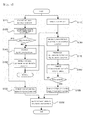
- Fig. 4 is a flow diagram of an error detecting method of the dual controller system according to the exemplary embodiment of the present invention.
- the first calculating unit 121 receives the sensing data from the sensor 110 and calculates and generates the first data (S11). While the step S11 is performed, the second calculating unit 131 receives the sensing data from the sensor 110 and calculates and generates the second data (S12).
- the first controller 120 and the second controller 130 compare the first data and the second data respectively. That is, the first comparing and controlling unit 123 compares the first data and the second data transmitted from the second controller 130 (S21) and detects the error, the second comparing unit 133 compares the second data and the first data received from the first controller 120 (S22) and detects the error.
- the first comparing and controlling unit 123 controls the first CAN module 125 to stop outputting the final data (S30). If the error is not detected from the steps S21 and S22, the first comparing and controlling unit 123 transmits the first output control signal to the first CAN module 125 (S40).
- the firs CAN module 125 operates according to the output control signal and processes the first data according to the CAN protocol to output the final data (S50).
- the second CAN module 135 processes the final data fed back from the CAN transceiver 140 according to the CAN protocol to transmit the third data (S60).
- the second comparing unit 133 compares the second data with the third data transmitted from the second CAN module 135 (S70). If the error is detected from the compared result at the step S70, the second control unit 134 transmits the interrupt signal to prevent the output of the final data to the first CAN module 125 (S80). If the error is not detected from the compared result at the step S70, the second control unit 134 transmits the second output control signal to the final CAN module 125 (S90). That is, the first CAN module 125 maintains a normal operation by the first and the second output control signal. Finally, the step returns to S11 and S12 to repeat the above processes.
- Fig. 5 is a schematic constitutional diagram of a dual controller system according to another exemplary embodiment of the present invention
- Fig. 6 is a schematic diagram to explain CAN message format including an indicator according to the another exemplary embodiment of the present invention.
- an error detecting device 200 of the dual controller system comprises a first controller 220, a second controller 230, a CAN transceiver 240 and an AND switching unit 250.
- the error detecting device 200 may further comprise a sensor 210, a first CAN transceiver control line 260, a second transceiver control line 270 and a feedback line 280.
- a real time calculating system for computing a steering angle of a steering wheel in a vehicle
- the present invention is not limited to the system but may also be applied to various error detecting devices adopting a dual controller system.
- the sensor 210 may be embodied as an AMR (Anisotropic Magneto Resistance) sensor for sensing the steering angle of the steering wheel.
- the sensor 210 may be provided as plural and the first and the second controllers 220, 230 may receive sensing data from a plurality of sensors respectively.
- the first controller 220 receives the sensing data from the sensor 210 and calculates and generates a first data. In this case, the first controller 220 generates the first data including the sensing data and an indicator. Then, the error of the input sensing data is detected. If the error is detected, the first off control signal is transmitted. For example, the error of the sensing data may be detected by checking if it deviates from a permitted limit through a predetermined number of samplings. As such an individual method for detecting the sensor error is widely known, its detail description is omitted.
- a CAN message format 300 may comprise a CAN ID area 310 of 11 bytes, a sensor data area 320 of 7 bytes and an indicator area of 1 byte.
- the indicator area is assigned to a partial area of the first data including the sensor sensing data
- the second controller 330 to be described later can synchronize the first data and the second data and compare both synchronized data to perform accurate error detection.
- the second controller 230 receives the sensing data from the sensor 210 and calculates and generates the second data.
- the second controller 230 may generates the second data according to a predetermined algorithm which is the same as that of the first controller 220. Also, the second controller 230 synchronizes the second data and the first data on the basis of the indicator included in the first data fed back from the first controller 220. Then, if the error is detected by comparing the second data with the first data, a second off control signal is transmitted.
- the CAN transceiver 240 receives the first data from the first controller 220 and transmits it through CAN bus. That is, the CAN transceiver 240, as a data transmission device, transmits the final steering angle data where the error is not detected to the vehicle network.
- the AND switching unit 250 outputs an interrupt signal, if at least one of the first and the second off control signals is received, to deactivate the CAN transceiver 240.
- the AND switching unit 250 has characteristics of a AND logic gate and outputs the interrupt signal, if it receives an off control signal from at least one of the first controller 220 and the second controller 230, to deactivate the CAN transceiver 240 for preventing an output of wrong data.
- a first CAN transceiver control line 260 is provided between the first controller 220 and the AND switching unit 250 to be a transmission line of the first off control signal.
- a second CAN transceiver control line 270 is provided between the second controller 230 and the AND switching unit 250 to be a transmission line of the second off control signal.
- a feedback line 280 diverges from an output terminal of the fist controller 220 and is connected to the second controller 230 to be a transmission line for feeding back the first data to the second controller 230.
- each controller identifies an error of final data respectively without communication between the controllers.
- output transmission to the vehicle is controlled to prevent output of dangerous data having errors, so that stability and reliability of the data communication can be increased.
- Fig. 7 is a detail constitutional diagram of the dual controller system according to the another exemplary embodiment of the present invention.
- the first controller 220 may comprise a first input unit 221, a first calculating unit 223, a first control unit 225 and a first CAN module 227.
- the first input unit 221 receives the sensing data from the sensor 210 per first time unit.
- the first time unit may be 2[ms].
- the first calculating unit 223 receives the sensing data and calculates and generates the first data. That is, the first calculating unit 223 performs transforming the sensor value received from the sensor 210 through a calculating unit into data recognizable by the controller. Also, the first calculating unit 223 may generate the first data including the sensing data and the indicator.
- the first control unit 225 detects the error by sampling the first data to predetermined times, and transmits the first off control signal to the AND switching unit 250 if the error is detected. However, if the error is not detected, the output control signal is transmitted to the first CAN module 227. That is, if the error is not detected from the first data, the first control unit 225 controls the first CAN module 227 for a normal output.
- the first CAN module 227 operates according to the output control signal, processes the first data according to the CAN protocol and transmits the final data.
- the second controller 230 may comprise a second input unit 231, a second calculating unit 233, a second comparing unit 234, a second control unit 235 and a second CAN module 237.
- the second input unit 231 receives the sensing data from the sensor 210 per first time unit.
- the first time unit may be 2[ms].
- the second calculating unit 233 receives the sensing data and calculates and generates the second data. That is, the second calculating unit 223 performs transforming the sensor value received from the sensor 210 through a calculating unit into data recognizable by the controller.
- the second comparing unit 234 synchronizes the first data and the second data on the basis of the indicator, and compares the synchronized second data and the first data to detect the error.
- the second control unit 235 if the error is detected by the second comparing unit 234, transmits the second off control signal to the AND switching unit 250. That is, if the error is detected by comparing the second data and the fed back first data, the second controller 235 prevents the output of the CAN transceiver 240.
- the second CAN module 237 processes the first data fed back from the first CAN module 227 and outputs it per second time unit.
- the second time unit may be 10[ms]. That is, the second CAN module 237 performs contrarily to the data transforming process of the first CAN module 227 to provide the second comparing unit 234 with the transformed first data.
- a first CAN transceiver control line 260 connects the first control unit 225 and a first input terminal of the AND switching unit 250 to provide a transmitting line of electrical signal
- a second CAN transceiver control line 270 connects the second control unit 235 and a second input terminal of the AND switching unit 250 to provide a transmitting line of electrical signal
- a feedback line 280 feeds back the first data output from the first CAN module 227 to the second CAN module 237.
- This exemplary embodiment is applied to SAS (Steering Angle Sensor) used in transmitting the steering angle to the vehicle and has its object of stopping the whole transmission in order not to transmit wrong information to the vehicle if the error occurs during operation and preventing malfunction of the vehicle by sensing abnormality from other systems using data of the SAS.
- SAS Steering Angle Sensor
- the sensor values input from the two sensors are transformed by the calculating unit into data recognizable in the vehicle, and the output is transmitted from the CAN controller to the CAN transceiver by the output control of the MCU1. Lastly, the CAN transceiver transmits it to the vehicle network.
- the information of a TX pin from the CAN controller of the MCU1 to the CAN transceiver is connected to a RX pin of the CAN controller of the MCU2.
- the CAN controller of the MCU2 recognizes the value from the MCU1 instead of the input value from the CAN transceiver as the RX and transmits the data to the comparing unit.
- the MCU2 compares an initial sensor calculating data received from the calculating unit and the value received from the CAN controller to compare the accuracy of the data and decide if an accurate value is transmitted to the vehicle network. If there is an error, the interrupt is engaged to the CAN transceiver.
- a recognizable indicator data is inserted at a part next to the area where the sensor value is used in the data value output by the MCU1, and is compared by the MCU2 for the synchronization. That is, when they are compared, the sensor measured data are synchronized and compared using the indicator of the data without direct synchronization of the MCU1 and the MCU2.
- period of recognizing the sensor input value by the MCU1 and the MCU2 is as short as about 2[ms].
- the MCU1 takes and outputs an average value through five times recognition.
- the period of the transmission to the vehicle is 10[ms], during which one data is transmitted.
- the MCU1 spares about 4 bits of the data area for the indicator with a counting of about 1 - 16 times and includes the indicator values in order and transmits the data.
- the MCU2 applies and calculates the average value through the five times recognition, calculates the indicator value with a counting of about 1 - 16 times, and compares the data value received at the 10[ms] period with the indicator value to check if the compared values are the same.
- the counting of the indicator at the first stage is performed after the same interval of 100 ⁇ 200 [ms] for normal operations of the MCU1, 2 where electric power has already been applied. If the indicator is incorrect repeatedly during operation or due to calculation error of the interval time at the first stage, the MCU2 performs correction as follows.
- the recognized counting value from the MCU1 is recognized as that from the MCU2 and the counting afterward is performed. Then, the number of the five times sampling for the average of the sensor input values is synchronized to a MCU1 feedback time of 10[ms] period from the counting for the indicator. At this time, the synchronization according to the data is set by decreasing or increasing the number of the five times sampling. If the synchronization is not set by the data within five times, or if the counting value of the indicator also has an error when the synchronization is to be set with an increase to ten times, a breakdown of the error is stored in the MCU and the CAN transceiver is deactivated.
- Fig. 8 is a flow diagram of an error detecting method of the dual controller system according to the another exemplary embodiment of the present invention.
- the first input unit in the first controller receives the sensing data per the first time unit.
- the first calculating unit 221 receives the sensing data from the sensor 210 and calculates and generates the first data including the indicator (S111).
- the second input unit in the second controller receives the sensing data from the sensor per the first time unit
- the second calculating unit 231 receives the sensing data from the sensor 210 and calculates and generates the second data (S112).
- the first time unit may be 2[ms].
- the first control unit 225 performs sampling the first data to predetermined times to detect the error (S120). In this case, the sampling times may be five. If the error is detected at the step S120, the first control unit 225 transmits the first off control signal to the AND switching unit 250 (S130). If the error is not detected at the step S120, the first control unit 225 transmits the output control signal to the first CAN module 227 to normally output the first data (S140). Then, the first CAN module 227 operates according to the output control signal, processes the first data according to the CAN protocol and outputs it (S150).
- the second CAN module 237 processes the first data fed back from the first CAN module 227 and outputs it per the second time unit (S160).
- the second time unit may be 10[ms].
- the second comparing unit 234 synchronizes the first data and the second data on the basis of the indicator included in the first data (S170). Then, the second comparing unit 234 compares the synchronized second data and first data to detect the error (S180). Therefore, as the indicator area is assigned to a partial area of the first data which includes the sensing data, the second controller 230 can synchronize the first data and the second data, compare both synchronized data and perform the accurate error detection.
- the second control unit 235 transmits the second off control signal to the AND switching unit 250 (S180). If the error is not detected at the step S120, a normal operation is maintained. That is, the first control unit 225 transmits the output control signal to the first CAN module 227 to normally output the first data (S140). In case of the normal output where the error is not detected, the steps return to S111 and S112 to repeat the above processes.
- the AND switching unit 250 receives at least one of the first and the second off control signals, it outputs the interrupt signal to deactivate the CAN transceiver 240 (S200).
- the AND switching unit 250 has characteristics of a AND logic gate and outputs the interrupt signal, if it receives the off control signal from at least one of the first controller 220 and the second controller 230, to deactivate the CAN transceiver 240 for preventing an output of wrong data.
- the error detecting device and method of a dual controller system of the present invention divide modules constituting the controller into detail areas, and detect communication between controllers and final data output to outside together so that output transmission to the vehicle is controlled if an error occurs in the areas. Also, a risk factor generated due to the error is verified in duplication to prevent output of dangerous data having errors, so that stability and reliability of the output data can be increased.
- each controller identifies an error of final data respectively without communication between the controllers.
- output transmission to the vehicle is controlled to prevent output of dangerous data having errors, so that stability and reliability of the data communication can be increased.
Landscapes
- Engineering & Computer Science (AREA)
- Theoretical Computer Science (AREA)
- Quality & Reliability (AREA)
- Physics & Mathematics (AREA)
- General Engineering & Computer Science (AREA)
- General Physics & Mathematics (AREA)
- Automation & Control Theory (AREA)
- Transportation (AREA)
- Mechanical Engineering (AREA)
- Human Computer Interaction (AREA)
- Chemical & Material Sciences (AREA)
- Combustion & Propulsion (AREA)
- Arrangements For Transmission Of Measured Signals (AREA)
- Safety Devices In Control Systems (AREA)
- Small-Scale Networks (AREA)
- Hardware Redundancy (AREA)
Applications Claiming Priority (3)
| Application Number | Priority Date | Filing Date | Title |
|---|---|---|---|
| KR1020110054381A KR101203872B1 (ko) | 2011-06-07 | 2011-06-07 | 듀얼 컨트롤러 시스템의 오류 검출 장치 및 방법 |
| KR1020110054382A KR101242398B1 (ko) | 2011-06-07 | 2011-06-07 | 듀얼 컨트롤러 시스템의 오류 검출 장치 및 방법 |
| PCT/KR2011/004925 WO2012169687A1 (fr) | 2011-06-07 | 2011-07-06 | Dispositif et procédé de détection d'erreur dans un système à double contrôleur |
Publications (2)
| Publication Number | Publication Date |
|---|---|
| EP2719599A1 true EP2719599A1 (fr) | 2014-04-16 |
| EP2719599A4 EP2719599A4 (fr) | 2017-05-10 |
Family
ID=47296228
Family Applications (1)
| Application Number | Title | Priority Date | Filing Date |
|---|---|---|---|
| EP11867253.4A Withdrawn EP2719599A4 (fr) | 2011-06-07 | 2011-07-06 | Dispositif et procédé de détection d'erreur dans un système à double contrôleur |
Country Status (4)
| Country | Link |
|---|---|
| US (1) | US9003271B2 (fr) |
| EP (1) | EP2719599A4 (fr) |
| CN (2) | CN102933443B (fr) |
| WO (1) | WO2012169687A1 (fr) |
Cited By (3)
| Publication number | Priority date | Publication date | Assignee | Title |
|---|---|---|---|---|
| WO2017167820A1 (fr) * | 2016-03-31 | 2017-10-05 | Connaught Electronics Ltd. | Unité de commande électronique pour un véhicule comprenant une connexion de données distincte, système et procédé d'assistance |
| GB2550412A (en) * | 2016-05-20 | 2017-11-22 | Ultra Electronics Ltd | System and method for protecting data integrity |
| DE102022203391A1 (de) | 2022-04-06 | 2023-10-12 | Zf Friedrichshafen Ag | Fahrzeugbordnetz zur redundanten Übertragung von Signalen |
Families Citing this family (36)
| Publication number | Priority date | Publication date | Assignee | Title |
|---|---|---|---|---|
| JP5766360B2 (ja) * | 2012-08-24 | 2015-08-19 | 三菱電機株式会社 | 車載通信システムおよび車載通信方法 |
| KR101369430B1 (ko) * | 2012-09-06 | 2014-03-06 | 주식회사 팬택 | 행 현상 관리 장치 및 방법 |
| DE102012111991A1 (de) * | 2012-11-20 | 2014-05-22 | Conti Temic Microelectronic Gmbh | Verfahren für eine Fahrerassistenzanwendung |
| DE102013202253A1 (de) * | 2013-02-12 | 2014-08-14 | Paravan Gmbh | Schaltung zur Steuerung eines Beschleunigungs-, Brems- und Lenksystems eines Fahrzeugs |
| KR101519777B1 (ko) * | 2014-01-29 | 2015-05-12 | 현대자동차주식회사 | 차량 네트워크 내의 제어기간의 데이터 송신 방법 및 수신 방법 |
| CN104005868B (zh) * | 2014-05-07 | 2016-11-23 | 潍柴动力股份有限公司 | 一种喷油提前角补偿方法及系统 |
| ES2952400T3 (es) | 2014-07-28 | 2023-10-31 | Mylaps B V | Módulo transpondedor y módulo de acceso para activar y configurar dicho módulo transpondedor |
| EP2981028B1 (fr) * | 2014-07-28 | 2020-05-06 | MyLaps B.V. | Module transpondeur et module d'accès permettant d'activer et de configurer ce module transpondeur sur un bus CAN |
| DE102015207895A1 (de) | 2015-04-29 | 2016-11-03 | Continental Automotive Gmbh | Verfahren zur Überwachung eines elektronischen Steuergeräts und Steuergerät für ein Kraftfahrzeug |
| GB2546789A (en) * | 2016-01-29 | 2017-08-02 | Bombardier Primove Gmbh | Arrangement with battery system for providing electric energy to a vehicle |
| DE102016009684A1 (de) * | 2016-08-10 | 2018-02-15 | Thyssenkrupp Ag | Regelung eines Steer-by-Wire-Lenksystems |
| JP6759858B2 (ja) * | 2016-08-26 | 2020-09-23 | 株式会社デンソー | センサ装置 |
| CA3035311C (fr) * | 2016-08-31 | 2023-08-29 | Beijing Surgerii Technology Co., Ltd. | Procede de detection de defaillance d'etat de fonctionnement d'un robot chirurgical |
| JP6761714B2 (ja) * | 2016-09-27 | 2020-09-30 | 株式会社Subaru | 車両用電子制御システム |
| JP6789159B2 (ja) * | 2017-03-21 | 2020-11-25 | 株式会社ケーヒン | 車両用制御装置 |
| EP3590037A4 (fr) * | 2017-07-25 | 2020-07-08 | Aurora Labs Ltd | Construction de mises à jour delta de logiciel pour un logiciel ecu de véhicule et détection d'anomalie basée sur une chaîne d'outils |
| JP7178774B2 (ja) * | 2017-09-01 | 2022-11-28 | 日立Astemo株式会社 | 移動体の運動制御装置、コンピュータプログラム、移動体の運動制御方法、および制御器 |
| FR3071800B1 (fr) * | 2017-09-29 | 2021-04-02 | Psa Automobiles Sa | Procede d’assistance a la conduite d’un vehicule lors d’une defaillance d’un reseau et systeme associe |
| CN109991954B (zh) * | 2017-12-29 | 2021-05-25 | 中兴通讯股份有限公司 | 电机控制器的容错控制方法、系统及设备、存储介质 |
| CN110371055B (zh) * | 2018-04-12 | 2022-09-23 | 上海汽车集团股份有限公司 | 一种汽车电源信号的解析方法及装置 |
| CN112622927A (zh) * | 2019-10-09 | 2021-04-09 | 宁波吉利汽车研究开发有限公司 | 一种车辆驾驶控制方法、装置、电子设备和存储介质 |
| US20220382239A1 (en) * | 2021-05-27 | 2022-12-01 | Fort Robotics, Inc. | Ensuring Functional Safety Requirement Satisfaction For Ouput Determination and Output of Safety Messages |
| US12587459B2 (en) | 2020-05-21 | 2026-03-24 | Fort Robotics, Inc. | Method for dynamic multihoming for reliable data transmission |
| CN112333066B (zh) * | 2020-09-29 | 2022-06-10 | 中国船舶重工集团公司第七0七研究所 | 一种提高can总线通讯可靠性的技术方法 |
| KR102844295B1 (ko) * | 2020-10-20 | 2025-08-12 | 주식회사 에이치엘클레무브 | 전자 제어 장치 및 방법 |
| CN114679374B (zh) * | 2020-12-24 | 2024-08-06 | 上海汽车集团股份有限公司 | 一种重置控制方法、装置及电子设备 |
| JP7472836B2 (ja) * | 2021-03-24 | 2024-04-23 | 株式会社デンソーウェーブ | 産業用制御装置 |
| US11500715B1 (en) * | 2021-05-27 | 2022-11-15 | Fort Robotics, Inc. | Determining functional safety state using software-based ternary state translation of analog input |
| US12530251B2 (en) * | 2021-05-27 | 2026-01-20 | Fort Robotics, Inc. | Determining functional safety state using software-based ternary state translation of analog input |
| CN113635919B (zh) * | 2021-09-06 | 2022-12-09 | 北京百度网讯科技有限公司 | 控制执行器的方法、装置、设备以及自动驾驶车辆 |
| CN113922904B (zh) * | 2021-10-10 | 2023-05-16 | 广州追梦软件技术有限公司 | 一种基于双控制器的调音台数据备份、切换方法 |
| EP4500801A4 (fr) | 2022-04-19 | 2025-06-11 | Fort Robotics, Inc. | Procédé de réponse de sécurité à des violations de politique de sécurité |
| US12081202B2 (en) | 2022-05-05 | 2024-09-03 | Fort Robotics, Inc. | Feedback-diverse, dual-controller-architecture functional safety system |
| DE102022002080B3 (de) | 2022-06-10 | 2023-07-27 | Mercedes-Benz Group AG | Batterie für ein Bordnetz eines Fahrzeugs |
| JP2025034218A (ja) * | 2023-08-30 | 2025-03-13 | 株式会社デンソー | 車両用電子制御装置及び方法 |
| IT202400000057A1 (it) * | 2024-01-04 | 2025-07-04 | St Microelectronics Int Nv | Sistema di elaborazione e relativo procedimento |
Family Cites Families (17)
| Publication number | Priority date | Publication date | Assignee | Title |
|---|---|---|---|---|
| FR2162093B1 (fr) * | 1971-12-02 | 1977-04-08 | Hitachi Ltd | |
| CA1320276C (fr) * | 1987-09-04 | 1993-07-13 | William F. Bruckert | Processeur double a correction des erreurs d'entree-sortie |
| US6111888A (en) * | 1997-05-27 | 2000-08-29 | Micro Motion, Inc. | Deterministic serial bus communication system |
| KR100284054B1 (ko) * | 1998-01-12 | 2001-03-02 | 구자홍 | 마이콤과 메인 시스템의 데이터 전송방법 및 장치 |
| US6988236B2 (en) * | 2000-04-07 | 2006-01-17 | Broadcom Corporation | Method for selecting frame encoding parameters in a frame-based communications network |
| JP3777398B2 (ja) * | 2000-04-26 | 2006-05-24 | 株式会社ジェイテクト | 車両用操舵制御装置 |
| JP3968972B2 (ja) * | 2000-08-14 | 2007-08-29 | 日本精工株式会社 | 電動パワーステアリング装置の制御装置 |
| DE10059769A1 (de) * | 2000-11-30 | 2002-06-06 | Philips Corp Intellectual Pty | Schaltungsanordnung zur Fehlererkennung eines Zweidraht-Datenbusses |
| JP2002354871A (ja) | 2001-05-25 | 2002-12-06 | Mitsubishi Electric Corp | 電動パワーステアリング装置 |
| US20050101314A1 (en) * | 2003-11-10 | 2005-05-12 | Uri Levi | Method and system for wireless group communications |
| US8428816B2 (en) * | 2007-10-27 | 2013-04-23 | GM Global Technology Operations LLC | Method and apparatus for monitoring software and signal integrity in a distributed control module system for a powertrain system |
| WO2009090502A1 (fr) * | 2008-01-16 | 2009-07-23 | Freescale Semiconductor, Inc. | Système basé sur un processeur et équipé d'un moyen d'informations de vérification par ecc et de validation d'accès |
| AT506439B1 (de) * | 2008-02-11 | 2012-11-15 | Tttech Computertechnik Ag | Redundantes bussystem |
| JP4613976B2 (ja) * | 2008-04-07 | 2011-01-19 | トヨタ自動車株式会社 | 車両の操舵制御装置 |
| DE102008002946B4 (de) * | 2008-07-16 | 2010-04-08 | Lear Corporation Gmbh | Verfahren zum Detektieren eines Fehlers auf einer Datenleitung |
| KR100998416B1 (ko) * | 2008-11-27 | 2010-12-03 | 대성전기공업 주식회사 | 듀얼 콘트롤러 시스템의 통신 중재 장치 및 방법 |
| KR20110020429A (ko) | 2009-08-24 | 2011-03-03 | 현대모비스 주식회사 | 정보교환을 통한 개별적인 이중 방식 이씨유 고장 판단방법 |
-
2011
- 2011-07-06 CN CN201180004628.3A patent/CN102933443B/zh not_active Expired - Fee Related
- 2011-07-06 US US13/511,129 patent/US9003271B2/en active Active
- 2011-07-06 WO PCT/KR2011/004925 patent/WO2012169687A1/fr not_active Ceased
- 2011-07-06 EP EP11867253.4A patent/EP2719599A4/fr not_active Withdrawn
- 2011-07-06 CN CN201510119331.1A patent/CN104709289B/zh not_active Expired - Fee Related
Cited By (5)
| Publication number | Priority date | Publication date | Assignee | Title |
|---|---|---|---|---|
| WO2017167820A1 (fr) * | 2016-03-31 | 2017-10-05 | Connaught Electronics Ltd. | Unité de commande électronique pour un véhicule comprenant une connexion de données distincte, système et procédé d'assistance |
| DE102016105876A1 (de) * | 2016-03-31 | 2017-10-05 | Connaught Electronics Ltd. | Elektronisches Steuergerät für ein Fahrzeug mit separater Datenverbindung, Assistenzsystem, Fahrzeug sowie Verfahren |
| GB2550412A (en) * | 2016-05-20 | 2017-11-22 | Ultra Electronics Ltd | System and method for protecting data integrity |
| GB2550412B (en) * | 2016-05-20 | 2021-09-15 | Ultra Electronics Ltd | System and method for protecting data integrity |
| DE102022203391A1 (de) | 2022-04-06 | 2023-10-12 | Zf Friedrichshafen Ag | Fahrzeugbordnetz zur redundanten Übertragung von Signalen |
Also Published As
| Publication number | Publication date |
|---|---|
| US20140108896A1 (en) | 2014-04-17 |
| CN104709289B (zh) | 2017-06-09 |
| CN102933443B (zh) | 2015-11-25 |
| CN104709289A (zh) | 2015-06-17 |
| CN102933443A (zh) | 2013-02-13 |
| WO2012169687A1 (fr) | 2012-12-13 |
| US9003271B2 (en) | 2015-04-07 |
| EP2719599A4 (fr) | 2017-05-10 |
Similar Documents
| Publication | Publication Date | Title |
|---|---|---|
| US9003271B2 (en) | Error detecting device and method of a dual controller system | |
| EP3668765B1 (fr) | Systèmes et procédés de détection de vitesse de roue redondante | |
| US8887022B2 (en) | Reliable data transmission with reduced bit error rate | |
| KR100998416B1 (ko) | 듀얼 콘트롤러 시스템의 통신 중재 장치 및 방법 | |
| EP2924578B1 (fr) | Clé d'authentification de processeur de moniteur pour données critiques | |
| KR101203872B1 (ko) | 듀얼 컨트롤러 시스템의 오류 검출 장치 및 방법 | |
| KR101242398B1 (ko) | 듀얼 컨트롤러 시스템의 오류 검출 장치 및 방법 | |
| US20170137035A1 (en) | Method for processing data for a driving function of a vehicle | |
| KR20160037939A (ko) | 안전-관련 적용의 리던던트 신호 처리를 위한 방법 및 전자 회로 장치, 차량 브레이크 시스템 및 이러한 차량 브레이크 시스템을 갖는 차량, 그리고 이러한 전자 회로 장치의 사용 | |
| EP1857937A1 (fr) | Dispositif de traitement de l'information et procede correspondant | |
| KR101242407B1 (ko) | 듀얼 컨트롤러 시스템의 오류 검출 장치 및 방법 | |
| US20190165968A1 (en) | Serial communication system | |
| US20080215913A1 (en) | Information Processing System and Information Processing Method | |
| AU2017312380B2 (en) | Arrangement having a safety-related system and method for the protected operation thereof by means of a remote query | |
| KR101242396B1 (ko) | 듀얼 코어 시스템의 오류 검출 장치 및 방법 | |
| US20190291663A1 (en) | Motor vehicle interface | |
| KR101273278B1 (ko) | 듀얼 코어 시스템의 오류 검출 장치 및 방법 | |
| US20070230464A1 (en) | Data Transmission Path Including a Device for Checking the Data Integrity | |
| US11409255B2 (en) | Output control apparatus | |
| US20200356715A1 (en) | System for producing a data stream on the basis of redundant information | |
| US10877919B2 (en) | Method to synchronize integrated circuits fulfilling functional safety requirements | |
| JP6059652B2 (ja) | 信号保安用制御装置 | |
| KR102844295B1 (ko) | 전자 제어 장치 및 방법 | |
| Errabelli et al. | A fault tolerant digital controller for power electronic applications | |
| US20090106461A1 (en) | Information Processing Apparatus and Information Processing Method |
Legal Events
| Date | Code | Title | Description |
|---|---|---|---|
| PUAI | Public reference made under article 153(3) epc to a published international application that has entered the european phase |
Free format text: ORIGINAL CODE: 0009012 |
|
| 17P | Request for examination filed |
Effective date: 20140102 |
|
| AK | Designated contracting states |
Kind code of ref document: A1 Designated state(s): AL AT BE BG CH CY CZ DE DK EE ES FI FR GB GR HR HU IE IS IT LI LT LU LV MC MK MT NL NO PL PT RO RS SE SI SK SM TR |
|
| DAX | Request for extension of the european patent (deleted) | ||
| RIC1 | Information provided on ipc code assigned before grant |
Ipc: B60W 50/02 20120101ALI20161221BHEP Ipc: B60W 10/20 20060101ALI20161221BHEP Ipc: G06F 11/07 20060101ALI20161221BHEP Ipc: G06F 11/16 20060101AFI20161221BHEP Ipc: B60R 16/023 20060101ALI20161221BHEP |
|
| RA4 | Supplementary search report drawn up and despatched (corrected) |
Effective date: 20170407 |
|
| RIC1 | Information provided on ipc code assigned before grant |
Ipc: B60W 10/20 20060101ALI20170403BHEP Ipc: G06F 11/07 20060101ALI20170403BHEP Ipc: B60W 50/02 20120101ALI20170403BHEP Ipc: B60R 16/023 20060101ALI20170403BHEP Ipc: G06F 11/16 20060101AFI20170403BHEP |
|
| 17Q | First examination report despatched |
Effective date: 20180110 |
|
| RAP1 | Party data changed (applicant data changed or rights of an application transferred) |
Owner name: LS AUTOMOTIVE CORP |
|
| RAP1 | Party data changed (applicant data changed or rights of an application transferred) |
Owner name: LS AUTOMOTIVE TECHNOLOGIES CO., LTD. |
|
| STAA | Information on the status of an ep patent application or granted ep patent |
Free format text: STATUS: THE APPLICATION IS DEEMED TO BE WITHDRAWN |
|
| 18D | Application deemed to be withdrawn |
Effective date: 20180523 |