EP2719643A1 - Procédé et dispositif d'orientation d'objets - Google Patents
Procédé et dispositif d'orientation d'objets Download PDFInfo
- Publication number
- EP2719643A1 EP2719643A1 EP13182044.1A EP13182044A EP2719643A1 EP 2719643 A1 EP2719643 A1 EP 2719643A1 EP 13182044 A EP13182044 A EP 13182044A EP 2719643 A1 EP2719643 A1 EP 2719643A1
- Authority
- EP
- European Patent Office
- Prior art keywords
- camera
- image
- actual
- orientation
- actual position
- Prior art date
- Legal status (The legal status is an assumption and is not a legal conclusion. Google has not performed a legal analysis and makes no representation as to the accuracy of the status listed.)
- Withdrawn
Links
Images


Classifications
-
- B—PERFORMING OPERATIONS; TRANSPORTING
- B65—CONVEYING; PACKING; STORING; HANDLING THIN OR FILAMENTARY MATERIAL
- B65G—TRANSPORT OR STORAGE DEVICES, e.g. CONVEYORS FOR LOADING OR TIPPING, SHOP CONVEYOR SYSTEMS OR PNEUMATIC TUBE CONVEYORS
- B65G47/00—Article or material-handling devices associated with conveyors; Methods employing such devices
- B65G47/22—Devices influencing the relative position or the attitude of articles during transit by conveyors
- B65G47/24—Devices influencing the relative position or the attitude of articles during transit by conveyors orientating the articles
- B65G47/244—Devices influencing the relative position or the attitude of articles during transit by conveyors orientating the articles by turning them about an axis substantially perpendicular to the conveying plane
-
- B—PERFORMING OPERATIONS; TRANSPORTING
- B65—CONVEYING; PACKING; STORING; HANDLING THIN OR FILAMENTARY MATERIAL
- B65G—TRANSPORT OR STORAGE DEVICES, e.g. CONVEYORS FOR LOADING OR TIPPING, SHOP CONVEYOR SYSTEMS OR PNEUMATIC TUBE CONVEYORS
- B65G47/00—Article or material-handling devices associated with conveyors; Methods employing such devices
- B65G47/22—Devices influencing the relative position or the attitude of articles during transit by conveyors
- B65G47/24—Devices influencing the relative position or the attitude of articles during transit by conveyors orientating the articles
-
- B—PERFORMING OPERATIONS; TRANSPORTING
- B25—HAND TOOLS; PORTABLE POWER-DRIVEN TOOLS; MANIPULATORS
- B25J—MANIPULATORS; CHAMBERS PROVIDED WITH MANIPULATION DEVICES
- B25J9/00—Program-controlled manipulators
- B25J9/16—Program controls
- B25J9/1694—Program controls characterised by use of sensors other than normal servo-feedback from position, speed or acceleration sensors, perception control, multi-sensor controlled systems, sensor fusion
- B25J9/1697—Vision controlled systems
-
- B—PERFORMING OPERATIONS; TRANSPORTING
- B65—CONVEYING; PACKING; STORING; HANDLING THIN OR FILAMENTARY MATERIAL
- B65G—TRANSPORT OR STORAGE DEVICES, e.g. CONVEYORS FOR LOADING OR TIPPING, SHOP CONVEYOR SYSTEMS OR PNEUMATIC TUBE CONVEYORS
- B65G2203/00—Indexing code relating to control or detection of the articles or the load carriers during conveying
- B65G2203/04—Detection means
- B65G2203/041—Camera
Definitions
- the invention relates to a method and a device for aligning an object such as a hollow body, wherein the object is supplied by means of a transport system such as a conveyor belt of an alignment and / or positioning, wherein by means of an image acquisition system, comprising a camera and running on a computer Software for evaluating a camera image of the object whose actual orientation and actual position is detected and the alignment and / or positioning device is actuated in response to the evaluation for changing the actual orientation and / or actual position of the object in a desired orientation and / or desired position.
- Such a conventional method or an associated device are known, for example, in the field of surface treatment, for example the decoration of hollow bodies such as bottles, glasses, bottles etc. of glass, plastic or metal or composite materials.
- the hollow bodies are conveyed via conveyor belts to the respective machines which carry out the decoration processes or the upstream or downstream processes in connection with the decoration.
- Such machines may include, for example, screen printing machines, pad printing machines, ink jet printing machines, Hot foil transfer machines, surface pretreatment machines, etc.
- an alignment and / or positioning device is arranged to correctly position the hollow body on conveyor belts and / or orient, so that in particular a commonly arranged gripping device, which is designed as an alignment and / or positioning device, receive the hollow body and the surface treatment process.
- the image data recorded by a camera about the actual orientation and actual position of the hollow body are used to control the alignment and / or positioning device. This control is all the more accurate and gentler, the more accurately the actual orientation and / or actual position of the object can be detected. Inadequate detection of the actual orientation or the actual position of the objects can lead to sensitive surfaces of the object being damaged by the alignment and / or positioning device.
- a comprehensive use of robots which detect the object like a hollow body by means of a camera image and subsequently position it, has so far failed, in particular, in a universally applicable illumination.
- the frequently very different geometries of the objects or hollow bodies in an industrial production environment in particular in the case of a glass material, have highly fluctuating optical reflection and transmission properties, which as a rule require individual lighting arrangements matched to the respective object.
- previously surface-treated objects such as lacquered, satined or etched objects for further surface refinement can be present, so that even with the same geometry of the objects alone, the changing surface texture leads to different lighting requirements.
- the invention is based on the object that conventional methods for aligning an object and an associated apparatus for performing the method so educate that it can be used universally.
- the inventive method is characterized in that image data of the object are recorded with a thermal imaging camera, which are evaluated and processed for detecting the actual orientation and / or actual position of the object, and wherein the object before recording the image data by a heat or Cold source is at least partially changed in its temperature.
- the object acts as a source of heat radiation, which is detected by the thermal imaging camera.
- the actual orientation and / or actual position of the object can be determined more accurately in comparison to the described conventional method, so that the alignment and / or positioning device can be adjusted more precisely to the respective alignment and / or positioning problem , which in particular surface damage to the article in its orientation can be substantially avoided.
- the alignment and / or positioning device can be designed, for example, as a robot system or as a stopper and slider system.
- the method according to the invention is expediently designed in such a way that the image information is restricted to regions of different temperatures, which simplifies a differentiation or differentiation of sections or parts of the object or a differentiation or differentiation of the object to the image background.
- the image information is reduced to temperature gradients within the image.
- the invention can be provided according to the invention to change the surface temperature of the article at least in sections even during the recording of a camera image. This can be done, for example, by irradiating the object by means of an infrared source. Depending on the specific detection problem, the irradiation can be partial with respect to the object, but in a specific embodiment it is also possible to irradiate the object to irradiate the entire surface by means of one or more infrared sources. It can also be provided to irradiate the object from several directions, in particular over a large solid angle.
- the surface temperature of the object can be at least partially changed by the use of a cold source to achieve a contrast increase or better differentiation within details of the object or the object from the background.
- the surface temperature of the background of the object is changed at least in sections prior to taking a camera image of the object to increase the contrast or for better differentiation of the object from the background.
- Such a modification can be carried out by means of a heat source and / or a cold source.
- the background of the object for the camera image is designed such that its emissivity is at least 10% relative to the infrared radiation detected by the camera, preferably differs by at least 20%, in particular preferably by at least 30% from the emissivity of at least a portion of the article.
- the object may expediently be exposed at least partially to a radiation-active source prior to the taking of a camera image, with the result of at least partial cooling of the object due to a radiation imbalance between the object and the cooling source.
- a radiation-active source prior to the taking of a camera image
- Such cooling in particular a partial cooling of the Object, ie a cooling of a surface portion of the object can be carried out according to the invention by means of an air flow, with which the object is flown.
- an air stream heated to the object may be used to heat the article.
- a particularly good detection of the actual orientation and / or actual position of the object can be achieved in that not only object images are recorded and processed by means of a thermal imaging camera, but also image data which has been recorded with a camera operating in the visible.
- both the data of an object image in the IR and data of an object image in the visible for detecting the actual orientation and / or actual position of the object can be used by the evaluation software.
- the image data in the IR or visible can be recorded simultaneously, which simplifies the processing of the data. It may be particularly expedient to use a camera device which is set up to record images both in the visible and in the IR and to provide the corresponding image data for further processing.
- the spectral range used by the thermal imaging camera can be within an interval of approximately 3.5 ⁇ m to 15 ⁇ m. However, it is also within the scope of the invention, To use a very narrow band spectral range in the IR, for example, less than 1 micron within the specified interval.
- the article is at least partially changed in its temperature by a heat or cold source placed opposite its base surface, wherein object images are received for further processing from above or below the base surface.
- standing surface refers to a curved or flat surface, with which the object from the ground, i. the transport system.
- partial means a partial region of the article, in particular a section of its surface.
- a heat or cold source placed laterally relative to the object, wherein an object image is picked up from the side. This means laterally or from the side approximately perpendicular to the base of the article, so taken in this embodiment side views of the article and initially for Be mood the actual orientation and / or actual position data are processed.
- the method according to the invention can also be expediently set up to determine the type of article, so that different objects, such as differently shaped hollow bodies, can be processed simultaneously, for example, into different desired positions and desired orientations or supplied to different surface treatment machines by means of the method according to the invention.
- the contour of the respective object can be detected and this detected object contour compared with a plurality of stored in a memory predetermined object contours of the different object types to determine the object type of the respective object.
- the inventive method can also be used to determine geometric data such as height and / or width of the object, which can also be used to determine the object type.
- the device according to the invention comprises a heat or cold source in order to change the object at least partially in its temperature before taking the image data.
- the device according to the invention may also include a heating or cooling device in order to change the surface temperature of the image background. This image background can be provided, for example, by a disk-like or planar device.
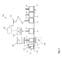
- FIG. 1 shows in a schematic diagram in section a inventively designed device 100 for implementing a method according to the invention for aligning a glass hollow body 10, 20, 30, which is supplied by means of a transport or conveyor belt 110 designed as a robot 150 alignment and positioning.
- the robot system 150 sets a predetermined target orientation and desired position of the respective glass hollow body 10, 20, 30, with which the object is fed to a respective associated printing press.
- the inventively embodied device 100 is designed not only to detect the actual orientation and actual position of an object and to set a predetermined desired position and desired orientation of the objects, but can also differentiate different types of glass objects 10, 20, 30, here hollow glass body in the form of bottles.
- the device is set up to supply each hollow glass body with a printing machine assigned to the respective hollow body type.
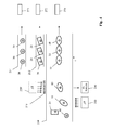
- FIG. 2 shows the in FIG. 1 indicated inventive device formed in a plan view.
- three different glass hollow body types 10, 20, 30 are first supplied to a stationary infrared source 120 in any order, orientation and position on the conveyor belt 110, wherein the different glass hollow body 10, 20, 30 on associated platforms 13, 23, 33 on the conveyor belt 110th support.
- a stationary infrared source 120 in any order, orientation and position on the conveyor belt 110, wherein the different glass hollow body 10, 20, 30 on associated platforms 13, 23, 33 on the conveyor belt 110th support.
- the objects are irradiated from above, ie from the opposite side to the respective footprint by means of a conventional, stationary infrared source 120, so that the respective glass hollow body at their short-side irradiated surfaces depending on the irradiation time, which by the speed of the conveyor belt and the lateral extent of the Heat source is determined in the direction of movement of the glass hollow body, heat.
- This heating leads to the hollow body and / or with respect to the conveyor belt 110 to a temperature gradient, which is detected by an arranged in the direction of movement of the conveyor belt 110 and stationary infrared camera 130.
- FIGS. 1 In the FIGS. 1 .
- the image forming part of the conveyor belt is in Fig. 2 designated by the reference numeral 180.
- the image data captured by the camera 130 are processed in a control device 140 for determining the actual orientation and actual position of the hollow glass body, this control device then activates the downstream robot system 150 for gripping the detected object and for setting a predetermined target orientation and position, so that the respective detected object the associated printing machine is supplied.
- FIG. 2 shows, three different glass hollow body 10, 20, 30 transported via the conveyor belt 110 in the described embodiment, wherein each object by the respective surface 13, 23, 33 opposite infrared camera image data are recorded, which by the control device 140 for determining the Actual position, characterized by the coordinates X, Y in the plane of the conveyor belt, as well as to determine the orientation or orientation, characterized by the angle ⁇ of a main axis of the object to the Y-axis in the plane defined by the conveyor belt 110, be used.
- the evaluation software is set up to detect and distinguish the three types of hollow glass bodies that are possible here. Since, in the example described, the three different types of glass bodies have to be supplied to different printing processes, which in FIG. 2 denoted by the reference numerals 170, 172 and 173 respectively, the robot system 150 is set up, each glass hollow body of the first type with a predetermined desired position and target orientation on the conveyor belt 110, moreover, each glass hollow body 20 of the second type with predetermined position and alignment on a second conveyor belt 112 and each glass hollow body 30 with a predetermined desired position and target orientation on a conveyor belt 114th
- the robot system 150 can grip the glass body exactly, which in turn can prevent surface damage to the hollow bodies.
- a software adaptation allows the quick conversion of the device or the method to different hollow body.
- hollow bodies made of standardized and automatically added and removed charge carriers, such as small pallets, thermoformed trays, etc. can also be processed with the method according to the invention or the specified device according to the invention in a further embodiment.
- the term actual position refers to the position of the bottleneck of the respective glass hollow body, projected onto the plane of the respective conveyor belt 110, 112 or 114. It is understood that, depending on the application, other reference points inside or outside of the respective article for determining the respective Coordinates can be selected.
- the apparatus 200 in turn comprises a conveyor belt 210, via which hollow bodies 10, 20, 30 of three different types are fed to a robot system 250, which is controlled by a control device 240 for setting a predetermined actual orientation and actual position of the respective objects 10, 20, 30.
- the articles are transported via the conveyor belt 210 to a laterally disposed stationary infrared source 220 which heats the respective article.
- a laterally arranged infrared camera 230 is provided, which creates a side view of the respective object, wherein laterally opposite to the camera an artificial image background in the form of a plate 280 is arranged to increase the differentiability of the object to the image background by a cold source 220 'can be cooled.
- the evaluation software in the control device 240 is able to detect not only the respective type, the actual position and the actual orientation of the respective glass hollow body, but also its width and height D, H in the image plane of the infrared camera , please refer FIG. 3 ,
- the image background is realized by a plate-shaped configuration 280, for example made of metal, this plate expediently arranged parallel to the image plane of the camera is.
- the temperature gradient in the hollow body and / or between the hollow body and the object background enables the acquisition of infrared image data which can be evaluated and processed for detecting the actual orientation and actual position of the respective object, so that subsequently the robot system 250 can be controlled by the control device 240 in order to place the respective object with a predetermined actual position and actual orientation on an associated conveyor belt 210, 212, 214, so that they are fed to their specific printing processes 270, 272, 274.
Landscapes
- Engineering & Computer Science (AREA)
- Mechanical Engineering (AREA)
- Length Measuring Devices By Optical Means (AREA)
- Manipulator (AREA)
- Control Of Conveyors (AREA)
- Attitude Control For Articles On Conveyors (AREA)
Applications Claiming Priority (1)
| Application Number | Priority Date | Filing Date | Title |
|---|---|---|---|
| DE102012218481.3A DE102012218481A1 (de) | 2012-10-10 | 2012-10-10 | Verfahren und Vorrichtung zum Ausrichten von Gegenständen |
Publications (1)
| Publication Number | Publication Date |
|---|---|
| EP2719643A1 true EP2719643A1 (fr) | 2014-04-16 |
Family
ID=49034005
Family Applications (1)
| Application Number | Title | Priority Date | Filing Date |
|---|---|---|---|
| EP13182044.1A Withdrawn EP2719643A1 (fr) | 2012-10-10 | 2013-08-28 | Procédé et dispositif d'orientation d'objets |
Country Status (4)
| Country | Link |
|---|---|
| US (1) | US20140107834A1 (fr) |
| EP (1) | EP2719643A1 (fr) |
| DE (1) | DE102012218481A1 (fr) |
| MX (1) | MX2013011725A (fr) |
Cited By (1)
| Publication number | Priority date | Publication date | Assignee | Title |
|---|---|---|---|---|
| FR3087367A1 (fr) * | 2018-10-22 | 2020-04-24 | Tiama | Procede et installation pour le marquage de recipients chauds en verre |
Families Citing this family (7)
| Publication number | Priority date | Publication date | Assignee | Title |
|---|---|---|---|---|
| CN105966882B (zh) * | 2016-07-16 | 2017-12-19 | 台州世控自动化设备有限公司 | 自动理标机 |
| CN106005974B (zh) * | 2016-07-16 | 2017-12-22 | 台州世控自动化设备有限公司 | 自动理标机 |
| CN106516661B (zh) * | 2016-12-30 | 2021-09-28 | 湖南千山制药机械股份有限公司 | 理瓶机 |
| CN107499918A (zh) * | 2017-07-21 | 2017-12-22 | 深圳市得可自动化设备有限公司 | 一种引导式视觉定位系统 |
| CN109178837A (zh) * | 2018-09-30 | 2019-01-11 | 东莞华贝电子科技有限公司 | 混料生产上料系统 |
| JP7639316B2 (ja) * | 2020-12-11 | 2025-03-05 | セイコーエプソン株式会社 | ソフトウェアスイッチプログラム、選択肢の選択方法および情報処理装置 |
| US20240260781A1 (en) * | 2023-02-03 | 2024-08-08 | Appliance Innovation, Inc. | Apparatus and method for automated preparation and delivery of beverages |
Citations (9)
| Publication number | Priority date | Publication date | Assignee | Title |
|---|---|---|---|---|
| US4147930A (en) * | 1975-03-20 | 1979-04-03 | U.S. Philips Corporation | Object location detector |
| GB2167211A (en) * | 1984-10-18 | 1986-05-21 | British Cast Iron Res Ass | Article recognition and handling system |
| FR2666316A1 (fr) * | 1990-09-04 | 1992-03-06 | France Etat | Dispositif de controle d'un flux d'objets en defilement continu, notamment de colis ou paquets postaux. |
| FR2697450A1 (fr) * | 1992-10-30 | 1994-05-06 | Felter Christian | Procédé et dispositif de triage d'objets défilant en continu et applications à des fruits et légumes. |
| JPH06307941A (ja) * | 1993-04-23 | 1994-11-04 | Kyosan Electric Mfg Co Ltd | ゴミ判別装置 |
| US5628409A (en) * | 1995-02-01 | 1997-05-13 | Beloit Technologies, Inc. | Thermal imaging refuse separator |
| WO2008085945A1 (fr) * | 2007-01-05 | 2008-07-17 | Valerio Thomas A | Système et procédé pour trier des matériaux différents |
| EP2174551A1 (fr) * | 2008-10-09 | 2010-04-14 | Cabinplant A/S | Procédé de traitement du poisson et usine de traitement du poisson |
| WO2012098430A1 (fr) * | 2011-01-19 | 2012-07-26 | Vistek Isra Vision Yapay Gorme Ve Otomasyon Sanayi Ve Ticaret Anonim Sirketi | Système de positionnement d'objets transparents |
Family Cites Families (9)
| Publication number | Priority date | Publication date | Assignee | Title |
|---|---|---|---|---|
| JP2001272209A (ja) * | 2000-03-23 | 2001-10-05 | Mitsubishi Electric Engineering Co Ltd | 発熱移動体の配列位置検出装置 |
| DE102005050902A1 (de) * | 2005-10-21 | 2007-05-03 | Khs Ag | Vorrichtung zum Ausrichten von Behältern sowie Etikettiermaschine mit einer solchen Vorrichtung |
| DE102006026618A1 (de) * | 2006-09-02 | 2008-03-13 | Khs Ag | Verfahren zum lagegenauen Aufbringen von Etiketten sowie Etikettiermaschine |
| FR2907370B1 (fr) * | 2006-10-18 | 2017-11-17 | Tiama | Procede et installation pour le marquage a chaud d'objets translucides ou transparents |
| CN103588154B (zh) * | 2008-05-20 | 2016-07-27 | 大日本印刷株式会社 | 饮料填充装置 |
| DE102008030290A1 (de) * | 2008-06-30 | 2009-12-31 | Khs Ag | Opto-elektrisches Erfassungssystem |
| DE102009039254A1 (de) * | 2009-08-28 | 2013-05-08 | Krones Aktiengesellschaft | Vorrichtung und Verfahren zum Inspizieren etikettierter Gefäße |
| US9671357B2 (en) * | 2009-12-10 | 2017-06-06 | Emhardt Glass S.A. | System and method for monitoring hot glass containers to enhance their quality and control the forming process |
| DE102010047621A1 (de) * | 2010-10-07 | 2012-04-12 | Krones Aktiengesellschaft | Vorrichtung und Verfahren zur Erkennung einer Drehstellung von Kunststoffvorformlingen |
-
2012
- 2012-10-10 DE DE102012218481.3A patent/DE102012218481A1/de not_active Withdrawn
-
2013
- 2013-08-28 EP EP13182044.1A patent/EP2719643A1/fr not_active Withdrawn
- 2013-10-08 MX MX2013011725A patent/MX2013011725A/es not_active Application Discontinuation
- 2013-10-10 US US14/050,608 patent/US20140107834A1/en not_active Abandoned
Patent Citations (9)
| Publication number | Priority date | Publication date | Assignee | Title |
|---|---|---|---|---|
| US4147930A (en) * | 1975-03-20 | 1979-04-03 | U.S. Philips Corporation | Object location detector |
| GB2167211A (en) * | 1984-10-18 | 1986-05-21 | British Cast Iron Res Ass | Article recognition and handling system |
| FR2666316A1 (fr) * | 1990-09-04 | 1992-03-06 | France Etat | Dispositif de controle d'un flux d'objets en defilement continu, notamment de colis ou paquets postaux. |
| FR2697450A1 (fr) * | 1992-10-30 | 1994-05-06 | Felter Christian | Procédé et dispositif de triage d'objets défilant en continu et applications à des fruits et légumes. |
| JPH06307941A (ja) * | 1993-04-23 | 1994-11-04 | Kyosan Electric Mfg Co Ltd | ゴミ判別装置 |
| US5628409A (en) * | 1995-02-01 | 1997-05-13 | Beloit Technologies, Inc. | Thermal imaging refuse separator |
| WO2008085945A1 (fr) * | 2007-01-05 | 2008-07-17 | Valerio Thomas A | Système et procédé pour trier des matériaux différents |
| EP2174551A1 (fr) * | 2008-10-09 | 2010-04-14 | Cabinplant A/S | Procédé de traitement du poisson et usine de traitement du poisson |
| WO2012098430A1 (fr) * | 2011-01-19 | 2012-07-26 | Vistek Isra Vision Yapay Gorme Ve Otomasyon Sanayi Ve Ticaret Anonim Sirketi | Système de positionnement d'objets transparents |
Cited By (2)
| Publication number | Priority date | Publication date | Assignee | Title |
|---|---|---|---|---|
| FR3087367A1 (fr) * | 2018-10-22 | 2020-04-24 | Tiama | Procede et installation pour le marquage de recipients chauds en verre |
| WO2020084239A1 (fr) | 2018-10-22 | 2020-04-30 | Tiama | Procede et installation pour le marquage de recipients chauds en verre |
Also Published As
| Publication number | Publication date |
|---|---|
| DE102012218481A1 (de) | 2014-04-10 |
| MX2013011725A (es) | 2014-04-25 |
| US20140107834A1 (en) | 2014-04-17 |
Similar Documents
| Publication | Publication Date | Title |
|---|---|---|
| DE102012218481A1 (de) | Verfahren und Vorrichtung zum Ausrichten von Gegenständen | |
| DE102009034529B4 (de) | Automatisches Führungs- und Erkennungssystem sowie Verfahren für dieses | |
| DE102018124079B4 (de) | Verfahren und Vorrichtung zum Ermitteln von Fehlstellen von Fasermaterialien | |
| DE3027373C2 (fr) | ||
| DE102013104545A1 (de) | Verfahren und Vorrichtung zum Erkennen von Fehlstellen von abgelegten Faserhalbzeugen | |
| EP2375243A1 (fr) | Procédé de contrôle thermographique et dispositif de contrôle pour l'exécution du procédé de contrôle | |
| DE102011083377A1 (de) | Vorrichtung und Verfahren zum Ausrichten von Behältern | |
| EP2605004A1 (fr) | Procédé et système de vérification de plusieurs objets pourvus d'une couche de barrière de gaz | |
| DE102016118670A1 (de) | Verfahren und Vorrichtung zur Prüfung von Preforms | |
| EP4145233A1 (fr) | Détermination du contour pour une machine de découpage au laser | |
| EP3862833A1 (fr) | Procédé de vérification d'un système d'assurance de qualité | |
| WO2018153837A1 (fr) | Blocage de lentilles | |
| DE102013110667B4 (de) | Verfahren zum bildgebenden zerstörungsfreien Prüfen von dreidimensionalen Werkstücken und Vorrichtung zur Durchführung eines derartigen Verfahrens | |
| WO2021013725A1 (fr) | Système de fabrication et procédé permettant de concevoir une machine-outil | |
| DE102021109286A1 (de) | Verfahren und Vorrichtung zum Inspizieren von Behältnissen mit Feststellung einer Drehstellung eines Behältnisverschlusses | |
| WO2010057592A1 (fr) | Procédé pour aligner un contenant | |
| EP2702352A1 (fr) | Dispositif d'analyse pour une analyse sans contact de la forme d'un corps transparent, et procédé pour la mise en oeuvre de l'analyse sans contact | |
| DE102005011330B4 (de) | Verfahren zur Lageerkennung eines Formteils | |
| EP3372331A1 (fr) | Procédé de répartition d'une pièce à usiner en forme de plaque | |
| EP4479210B1 (fr) | Système d'étalonnage et procédé d'étalonnage pour étalonner un système de plateforme de construction dans un dispositif de fabrication additive | |
| EP3754293B1 (fr) | Procédé de mesure du format d'une pièce en forme de plaque | |
| DE102024101048A1 (de) | Vorrichtung und Verfahren zum Herstellen von Kunststoffvorformlingen mit Infrarot-Bildaufnahmeeinrichtung | |
| DE102022110658A1 (de) | Verfahren zum Vermessen einer Bauplattform einer generativen Fertigungsvorrichtung, Steuervorrichtung zur Durchführung eines solchen Verfahrens, generative Fertigungsvorrichtung mit einer solchen Steuervorrichtung, Verfahren zum generativen Fertigen eines Bauteils und Computerprogrammprodukt | |
| DE102018125036A1 (de) | Vorrichtung zum Umformen eines insbesondere metallischen Werkstücks | |
| DE10303459A1 (de) | Verfahren und Vorrichtung zum Kontrollieren des Randes eines scheibenförmigen Gegenstandes |
Legal Events
| Date | Code | Title | Description |
|---|---|---|---|
| PUAI | Public reference made under article 153(3) epc to a published international application that has entered the european phase |
Free format text: ORIGINAL CODE: 0009012 |
|
| AK | Designated contracting states |
Kind code of ref document: A1 Designated state(s): AL AT BE BG CH CY CZ DE DK EE ES FI FR GB GR HR HU IE IS IT LI LT LU LV MC MK MT NL NO PL PT RO RS SE SI SK SM TR |
|
| AX | Request for extension of the european patent |
Extension state: BA ME |
|
| RAP1 | Party data changed (applicant data changed or rights of an application transferred) |
Owner name: KBA-KAMMANN GMBH |
|
| STAA | Information on the status of an ep patent application or granted ep patent |
Free format text: STATUS: THE APPLICATION HAS BEEN WITHDRAWN |
|
| 18W | Application withdrawn |
Effective date: 20140530 |