EP2719918A1 - Magnetischer und visköser dämmstoff - Google Patents
Magnetischer und visköser dämmstoff Download PDFInfo
- Publication number
- EP2719918A1 EP2719918A1 EP12801131.9A EP12801131A EP2719918A1 EP 2719918 A1 EP2719918 A1 EP 2719918A1 EP 12801131 A EP12801131 A EP 12801131A EP 2719918 A1 EP2719918 A1 EP 2719918A1
- Authority
- EP
- European Patent Office
- Prior art keywords
- cylinder
- magnetorheological fluid
- piston
- shock absorber
- disposed
- Prior art date
- Legal status (The legal status is an assumption and is not a legal conclusion. Google has not performed a legal analysis and makes no representation as to the accuracy of the status listed.)
- Withdrawn
Links
Images


Classifications
-
- F—MECHANICAL ENGINEERING; LIGHTING; HEATING; WEAPONS; BLASTING
- F16—ENGINEERING ELEMENTS AND UNITS; GENERAL MEASURES FOR PRODUCING AND MAINTAINING EFFECTIVE FUNCTIONING OF MACHINES OR INSTALLATIONS; THERMAL INSULATION IN GENERAL
- F16F—SPRINGS; SHOCK-ABSORBERS; MEANS FOR DAMPING VIBRATION
- F16F9/00—Springs, vibration-dampers, shock-absorbers, or similarly-constructed movement-dampers using a fluid or the equivalent as damping medium
- F16F9/32—Details
- F16F9/53—Means for adjusting damping characteristics by varying fluid viscosity, e.g. electromagnetically
- F16F9/535—Magnetorheological [MR] fluid dampers
Definitions
- This invention relates to a magnetorheological fluid shock absorber that uses a magnetorheological fluid having an apparent viscosity that is varied by an action of a magnetic field.
- a damping force of a shock absorber installed in a vehicle such as an automobile may be varied by applying a magnetic field to a flow passage through which a magnetorheological fluid passes in order to vary an apparent viscosity of the magnetorheological fluid.
- JP2007-239982A discloses a magnetorheological fluid shock absorber in which a permanent magnet is attached to respective axial direction end portions of a cylinder in which a magnetorheoloigcal fluid is sealed.
- a magnetorheological fluid shock absorber a yoke material is provided on an outer periphery of the cylinder, and a piston and a part of a piston rod are formed from a ferromagnetic material.
- a magnetic force of the permanent magnet does not act on the magnetorheological fluid.
- the magnetorheological fluid shock absorber is structured such that a periphery of a magnetic field generation device is covered by the magnetorheological fluid, and therefore a magnetic field generated by the magnetic field generation device disperses such that magnetism cannot be applied to the magnetorheological fluid efficiently.
- This invention has been designed in consideration of the problems described above, and an object thereof is to provide a magnetorheological fluid shock absorber in which a magnet is attached to a cylinder, and with which magnetism is applied efficiently so that a damping coefficient is varied continuously relative to a stroke amount of a piston.
- a magnetorheological fluid shock absorber that uses a magnetorheological fluid having a viscosity that is varied by an action of a magnetic field.
- the magnetorheological fluid shock absorber includes: a tubular cylinder formed from a non-magnetic material and having the magnetorheological fluid sealed into an inner periphery thereof; a piston formed from a non-magnetic material and disposed in the cylinder to be free to slide at an interval, through which the magnetorheological fluid can pass, relative to the inner periphery of the cylinder; a piston rod to which the piston is connected; and a magnet portion attached to the cylinder in order to apply a magnetic field to an interior of the cylinder.
- the magnet portion includes a permanent magnet having an inner peripheral shape that aligns with an outer periphery of the cylinder; and a ring member formed from a magnetic material and disposed on an outer peripheral side of the permanent magnet.
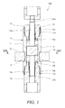
- FIG. 1 is a sectional view of the magnetorheological fluid shock absorber 100.
- the magnetorheological fluid shock absorber 100 is a damper in which a damping coefficient relative to a force applied in an axial direction can be varied using a magnetorheological fluid that is varied in viscosity by an action of a magnetic field.
- the magnetorheological fluid shock absorber 100 is formed such that the damping coefficient thereof varies proportionally in accordance with a stroke amount of a piston 21.
- the magnetorheological fluid shock absorber 100 includes a tubular cylinder 10 having a magnetorheological fluid sealed into an inner periphery thereof, the piston 21, which is disposed in the cylinder 10 to be free to slide in an axial direction of the cylinder 10, a piston rod 22 to which the piston 21 is connected, and a magnet portion 30 that is fixed to an outer periphery of the cylinder 10 in order to apply a magnetic field to an interior of the cylinder 10.
- the magnetorheological fluid sealed in the cylinder 10 is a fluid formed by dispersing ferromagnetic microparticles through a fluid such as oil, and has an apparent viscosity that is varied by an action of a magnetic field.
- the viscosity of the magnetorheological fluid varies in accordance with an intensity of the applied magnetic field, and reaches a minimum when no magnetic field effect is present.
- the cylinder 10 includes a cylindrical portion 11 formed in a cylindrical shape having opening portions at either end, and a head member 12 and a bottom member 13 respectively attached to the opening portions at either end of the cylindrical portion 11.
- the cylindrical portion 11 includes a screw portion 11a formed on an inner periphery in one opening portion, and a screw portion 11b formed on an inner periphery in the other opening portion.
- a screw portion 12b that is screwed to the screw portion 11a of the cylindrical portion 11 is formed on an outer periphery of the head member 12.
- a seal member 14a is provided between the inner periphery of the cylindrical portion 11 and the outer periphery of the head member 12 so that the magnetorheological fluid is sealed within the cylinder 10.
- a hole 12a for inserting the piston rod 22 is formed in the head member 12.
- a screw portion 13b that is screwed to the screw portion 11b of the cylindrical portion 11 is formed on an outer periphery of the bottom member 13.
- a seal member 14b is provided between the inner periphery of the cylindrical portion 11 and the outer periphery of the bottom member 13 so that the magnetorheological fluid is sealed within the cylinder 10.
- a hole 13a for inserting the piston rod 22 is formed in the bottom member 13.
- the cylinder 10 includes an annular recessed portion 15 formed on the outer periphery of the cylindrical portion 11 to be thinner than other parts of the cylinder 10.
- the magnet portion 30 is fitted around the recessed portion 15.
- the piston 21 is formed in a columnar shape having a smaller outer diameter than an inner diameter of the cylindrical portion 11 of the cylinder 10. In other words, the piston 21 is formed at an annular interval, through which the magnetorheological fluid can pass, relative to the inner periphery of the cylindrical portion 11 of the cylinder 10.
- the magnetorheological fluid passes through the interval between the piston 21 and the cylinder 10.
- the annular interval between the piston 21 and the cylinder 10 serves as a throttle by which the magnetorheological fluid shock absorber 100 generates a damping force.
- the piston rod 22 is formed coaxially with the piston 21, and penetrates a center of the piston 21.
- the piston rod 22 is formed integrally with the piston 21.
- the piston rod 22 may be formed separately from the piston 21 and joined thereto by a screw or the like.
- One end portion 22a of the piston rod 22 penetrates the hole 12a in the head member 12 and extends to the outside of the cylinder 10 while being supported by the head member 12 to be free to slide.
- Another end portion 22b of the piston rod 22 penetrates the hole 13a in the bottom member 13 and is supported by the bottom member 13 to be free to slide.
- the piston rod 22 By supporting the piston rod 22 to be free to slide using the head member 12 and the bottom member 13 in this manner, the piston rod 22 can slide through the cylinder 10 in the axial direction without deviating in a radial direction even though the annular interval is formed between the outer periphery of the piston 21 and the inner periphery of the cylinder 10.
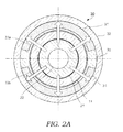
- FIG. 2A is a IIA-IIA sectional view of FIG. 1 .
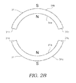
- FIG. 2B is a view illustrating a permanent magnet 31 of the magnetorheological fluid shock absorber 100 according to the first embodiment of this invention.
- the magnet portion 30 is formed with an annular cross-section.
- the magnet portion 30 is fitted around the recessed portion 15 of the cylinder 10.
- the recessed portion 15 is formed to be thinner than the other parts of the cylinder 10. As a result, the magnetic field from the magnet portion 30 is not prevented from acting on the magnetorheological fluid sealed in the cylinder 10.
- the magnet portion 30 is constituted by a pair of permanent magnets 31, a support member 33 supporting the permanent magnets 31, and an annular magnetic ring member 32 fitted around the permanent magnets 31 and the support member 33.
- Each permanent magnet 31 is a C-shaped segment magnet having an arc shape that is surrounded by an inner peripheral surface 31a constituted by a partial arc of a first circumference centering on an identical axis to an axial center of the cylinder 10, an outer peripheral surface 31b constituted by a partial arc of a second circumference that is concentric with the first circumference but has a larger diameter than the first circumference, and a pair of side portions 31c linking the inner peripheral surface 31a to the outer peripheral surface 31b.
- the pair of permanent magnets 31 are formed in an identical shape and disposed symmetrically about the central axis of the cylinder 10.
- the permanent magnets 31 are magnetized by groups of magnetic poles in a radial direction.
- the permanent magnets 31 are respectively magnetized to an N pole on the inner peripheral surface 31a side and an S pole on the outer peripheral surface 31b side.
- the pair of permanent magnets 31 are disposed such that the respective magnetic poles thereof oppose each other about the central axis of the cylinder 10.
- the pair of permanent magnets 31 are magnetized in an identical direction to each other and disposed in line symmetry about a line segment passing through the central axis of the cylinder 10.
- An inner peripheral side of the support member 33 is formed in a cylindrical shape that aligns with the periphery of the recessed portion 15 formed in an annular shape.
- a groove portion 33a and a groove portion 33b are formed on an outer peripheral side of the support member 33 to fix the permanent magnets 31 to an outer circumferential form thereof.
- the outer periphery of the support member 33 forms an identical circle to the aforesaid second circumference.
- the support member 33 is formed from a non-magnetic material, similarly to the cylinder 10. In so doing, the support member 33 is prevented from forming a magnetic path, and therefore the magnetic field from the magnet portion 30 is applied to the magnetorheological fluid efficiently.
- the annular magnetic ring member 32 is formed from a magnetic material and fitted to the outer periphery of the support member 33.
- the magnetic ring member 32 is fitted tightly to the outer periphery of the support member 33 in a condition where the permanent magnets 31 are fixed respectively to the groove portion 33a and the groove portion 33b.
- the magnetic ring member 32 forms a magnetic path for a magnetic field generated by the permanent magnets 31.
- the magnetic ring member 32 is formed from a soft magnetic material having a high permeability and a low coercive force relative to a residual magnetic field.
- the pair of permanent magnets 31 are fixed by the support member 33 so as to be removed from each other.
- a central angle of the inner peripheral surface 31a and the outer peripheral surface 31b of the permanent magnet 31 is set at less than 180°. Further, the outer peripheral surface 31b of the permanent magnet 31 closely contacts an inner peripheral surface of the magnetic ring member 32.
- the magnet portion 30 generates a magnetic field in a direction indicated by an arrow in FIG. 2A . More specifically, by disposing the pair of permanent magnets 31 such that the magnetic poles thereof oppose each other, magnetic force is generated in a radial direction from the central axis of the cylinder 10. This magnetic force is applied evenly to the magnetorheological fluid existing in the interval between the piston 21 and the cylinder 10, enabling an increase in the viscosity of the magnetorheological fluid.
- the magnetic ring member 32 made of a magnetic material is disposed on the outer side of the permanent magnets 31, and therefore a magnetic field heading toward the outer peripheral surface 31b side passes through the interior of the magnetic ring member 32 without dispersing. Hence, the magnetic field can be applied to the magnetorheological fluid more efficiently.
- the magnet portion 30 is disposed to correspond to a position of the piston 21 when the piston rod 22 is furthest advanced into the cylinder 10.
- the viscosity of the magnetorheological fluid in the cylinder 10 differs according to the axial direction position. More specifically, the ferromagnetic microparticles gather in the vicinity of the magnet portion 30 due to an increase in the effect of the magnetic field, and therefore the viscosity of the magnetorheological fluid in the cylinder 10 increases gradually toward the magnet portion 30. Away from the magnet portion 30, on the other hand, the effect of the magnetic field decreases, leading to a reduction in the viscosity of the magnetorheological fluid in the cylinder 10.
- the damping coefficient of the magnetorheological fluid shock absorber 100 increases as the piston rod 22 advances into the cylinder 10, and as a result, the damping coefficient can be varied continuously in accordance with the stroke amount of the piston 21.
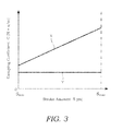
- the annular interval serving as the throttle between the piston 21 and the cylinder 10 remains constant at all times, even when the piston rod 22 advances into the cylinder 10. Further, since the magnet portion 30 is not provided, the magnetorheological fluid in the cylinder 10 is not affected by a magnetic field, and therefore the viscosity of the magnetorheological fluid in the cylinder 10 remains constant regardless of the stroke amount of the piston rod 22. Hence, as shown by the straight line Y, the damping coefficient C in this case takes a constant value at all times relative to variation in the stroke amount S.
- the damping coefficient C is at a minimum when the stroke amount is S min , i.e. when the piston rod 22 is furthest withdrawn from the cylinder 10. Even when the stroke amount is S min , however, the magnetic field generated by the magnet portion 30 affects the magnetorheological fluid in the cylinder 10 such that the ferromagnetic microparticles are aligned, and therefore the damping coefficient C is larger than that of the case in which the magnet portion 30 is not provided.
- the damping coefficient C increases proportionally, and when the stroke amount reaches S max , the damping coefficient C reaches a maximum.
- the reason for this is that the viscosity of the magnetorheological fluid in the annular interval between the piston 21 and the cylinder 10 gradually increases.
- a length of the annular interval between the piston 21 and the cylinder 10 that is directly affected by the magnetic field gradually increases.
- the damping coefficient C of the magnetorheological fluid shock absorber 100 can be increased proportionally relative to the stroke amount of the piston rod 22 in the advancement direction into the cylinder 10.
- the cylinder 10 and the piston 21 are formed from a non-magnetic material, and the magnet portion 30 that applies a magnetic field to the magnetorheological fluid in the cylinder 10 is attached to the cylinder 10.
- the cylinder 10 and the piston 21 do not form a magnetic path, and therefore the effect of the magnetic field on the magnetorheological fluid passing through the interval between the cylinder 10 and the piston 21 increases gradually as the piston 21 strokes toward the magnet portion 30.
- the damping coefficient can be varied continuously relative to the stroke amount of the piston 21.
- the magnet portion 30 includes the pair of permanent magnets 31 constituted by C-shaped segment magnets respectively having an inner peripheral shape that aligns with the outer peripheral shape of the cylindrical cylinder 10 in which the magnetorheological fluid is sealed.
- the magnetic field acts on the magnetorheological fluid existing in the interval between the piston 21 and the cylinder 10, leading to an increase in the viscosity of the magnetorheological fluid.
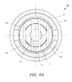
- FIG. 4A is a sectional view of the cylinder 10 and the magnet portion 30 of a magnetorheological fluid shock absorber according to the second embodiment of this invention
- FIG. 4B is a view illustrating the permanent magnets 31 of the magnetorheological fluid shock absorber according to the second embodiment of this invention
- FIG. 5A is a sectional view of the cylinder 10 and the magnet portion 30 of a modified example of magnetorheological fluid shock absorber according to the second embodiment of this invention
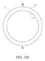
- FIG. 5B is a view illustrating the permanent magnets 31 of the modified example of the magnetorheological fluid shock absorber 100 according to the second embodiment of this invention.
- the magnetorheological fluid shock absorber according to the second embodiment has an identical overall basic configuration to the magnetorheological fluid shock absorber 100 according to the first embodiment, shown in FIG. 1 .
- the magnetorheological fluid shock absorber according to the second embodiment differs from the magnetorheological fluid shock absorber 100 according to the first embodiment only in the configuration of the magnet portion 30.
- Each permanent magnet 31 is a C-shaped segment magnet.
- the pair of permanent magnets 31 are formed in an identical shape and disposed symmetrically about the central axis of the cylinder 10.
- the permanent magnets 31 are magnetized by groups of magnetic poles in the radial direction, as shown in FIG. 4B .
- one of the permanent magnets 31 is magnetized to an N pole on the inner peripheral surface 31a side and an S pole on the outer peripheral surface 31b side.
- the other permanent magnet 31 is magnetized to an S pole on the inner peripheral surface 31a side and an N pole on the outer peripheral surface 31 b side.
- the pair of permanent magnets 31 are disposed in the magnet portion 30 such that opposite magnetic poles oppose each other about the central axis of the cylinder 10. In other words, the magnetic poles of the pair of permanent magnets 31 differ from each other.
- the magnet portion 30 generates a magnetic field in the direction of an arrow shown in FIG. 4A .
- the pair of permanent magnets 31 so that opposite magnetic poles oppose each other, magnetic force traveling from one of the permanent magnets 31 toward the other permanent magnet 31 is generated.
- This magnetic force is applied to the magnetorheological fluid existing in the interval between the piston 21 and the cylinder 10, leading to an increase in the viscosity of the magnetorheological fluid.
- a magnetic field is generated around a peripheral surface of the cylinder 10 in a direction following the peripheral surface of the cylinder 10 particularly in the vicinity of a boundary between the pair of permanent magnets 31. Therefore, the magnetic field can be applied to the magnetorheological fluid effectively.
- the magnetic ring member 32 made of a magnetic material is disposed on the outer side of the permanent magnets 31, and therefore a magnetic field traveling from one of the permanent magnets 31 toward the other permanent magnet 31 passes through the magnetic ring member 32 without dispersing. Hence, the magnetic field can be applied to the magnetorheological fluid efficiently.
- the pair of permanent magnets 31 are disposed such that opposite magnetic poles oppose each other about the central axis of the cylinder 10. In other words, different magnetic poles oppose each other on the inner peripheral side of the permanent magnets 31.
- a similar magnetic field may be formed by forming the permanent magnet 31 in a ring shape and magnetizing the permanent magnet 31 such that different magnetic poles oppose each other on the inner peripheral side thereof. More specifically, in the permanent magnet 31 formed in a ring shape, one half circumference part of the permanent magnet 3 1 is magnetized to an N pole and the other half circumference part is magnetized to an S pole.
- the support member 33 is formed without the groove portions, and has an outer peripheral shape that aligns with the inner periphery of the ring-shaped permanent magnet 31.
- the magnet portion 30 generates a magnetic field in the direction of an arrow shown in FIG. 5A .
- a magnetic field traveling from the N pole toward the S pole is generated in the ring-shaped permanent magnet 31.
- the magnetic field acts on the magnetorheological fluid existing in the interval between the piston 21 and the cylinder 10, leading to an increase in the viscosity of the magnetorheological fluid.
- a magnetic field that is substantially parallel to the peripheral surface of the cylinder 10 is generated along the peripheral surface of the cylinder 10 particularly in the vicinity of a boundary between the N pole and the S pole of the ring-shaped permanent magnet 31. Therefore, the magnetic field can be applied to the magnetorheological fluid effectively.
- the damping coefficient can be varied continuously relative to the stroke amount of the piston 21.
- the pair of permanent magnets 31 are constituted by C-shaped segment magnets having an inner peripheral shape that aligns with the outer peripheral shape of the cylindrical cylinder 10 in which the magnetorheological fluid is sealed, and the magnetic poles thereof are disposed such that opposite magnetic poles oppose each other.
- a magnetic field is generated in a direction following the peripheral surface of the cylinder 10, and therefore the magnetic field can be applied to the magnetorheological fluid effectively.
- the magnetic ring member 32 made of a magnetic material is disposed on the outer side of the permanent magnets 31, and therefore the magnetic field traveling from one of the permanent magnets 31 toward the other permanent magnet 31 passes through the interior of the magnetic ring member 32 without dispersing. Hence, the magnetic field can be applied to the magnetorheological fluid more efficiently.
- Tokugan 2011-131257 The contents of Tokugan 2011-131257 , with a filing date of June 13, 2011 in Japan, are hereby incorporated by reference.
Landscapes
- Engineering & Computer Science (AREA)
- General Engineering & Computer Science (AREA)
- Physics & Mathematics (AREA)
- Electromagnetism (AREA)
- Mechanical Engineering (AREA)
- Fluid-Damping Devices (AREA)
- Vibration Prevention Devices (AREA)
Applications Claiming Priority (2)
| Application Number | Priority Date | Filing Date | Title |
|---|---|---|---|
| JP2011131257A JP5821095B2 (ja) | 2011-06-13 | 2011-06-13 | 磁気粘性流体緩衝器 |
| PCT/JP2012/063708 WO2012172961A1 (ja) | 2011-06-13 | 2012-05-29 | 磁気粘性流体緩衝器 |
Publications (2)
| Publication Number | Publication Date |
|---|---|
| EP2719918A1 true EP2719918A1 (de) | 2014-04-16 |
| EP2719918A4 EP2719918A4 (de) | 2016-03-30 |
Family
ID=47356954
Family Applications (1)
| Application Number | Title | Priority Date | Filing Date |
|---|---|---|---|
| EP12801131.9A Withdrawn EP2719918A4 (de) | 2011-06-13 | 2012-05-29 | Magnetischer und visköser dämmstoff |
Country Status (6)
| Country | Link |
|---|---|
| US (1) | US20140116827A1 (de) |
| EP (1) | EP2719918A4 (de) |
| JP (1) | JP5821095B2 (de) |
| KR (2) | KR20140012172A (de) |
| CN (1) | CN103562591B (de) |
| WO (1) | WO2012172961A1 (de) |
Families Citing this family (3)
| Publication number | Priority date | Publication date | Assignee | Title |
|---|---|---|---|---|
| CN104141730B (zh) * | 2014-06-30 | 2016-08-24 | 北京交通大学 | 一种磁固式磁性液体阻尼减振器 |
| KR102481566B1 (ko) * | 2020-12-28 | 2022-12-26 | 한국해양과학기술원 | 엠알(mr) 유체 댐퍼 |
| CN119982820B (zh) * | 2025-04-14 | 2025-06-24 | 宁波玛仕电磁科技有限公司 | 一种磁流变减振器 |
Family Cites Families (25)
| Publication number | Priority date | Publication date | Assignee | Title |
|---|---|---|---|---|
| JPS5610844A (en) * | 1979-07-02 | 1981-02-03 | Toyota Motor Corp | Feedback control system vibration absorbing suspension |
| JPS57161330A (en) * | 1981-03-27 | 1982-10-04 | Matsushita Electric Works Ltd | Oil dashpot |
| JPS60121948A (ja) * | 1983-12-01 | 1985-06-29 | Nippon Denso Co Ltd | 電気回転機械の磁石回転子の永久磁石固定方式 |
| US5105114A (en) * | 1991-05-20 | 1992-04-14 | General Motors Corporation | Frame and magnet assembly for a dynamoelectric machine |
| JPH0552235A (ja) * | 1991-08-23 | 1993-03-02 | Toshiba Corp | 粘性ダンパ |
| JPH0541357U (ja) * | 1991-11-05 | 1993-06-01 | 株式会社荻原製作所 | 永久磁石回転子および電動機 |
| US5947238A (en) * | 1997-03-05 | 1999-09-07 | Lord Corporation | Passive magnetorheological fluid device with excursion dependent characteristic |
| US6471018B1 (en) * | 1998-11-20 | 2002-10-29 | Board Of Regents Of The University And Community College System On Behalf Of The University Of Nevada-Reno, The University Of Reno | Magneto-rheological fluid device |
| US6279700B1 (en) * | 1999-09-13 | 2001-08-28 | Delphi Technologies, Inc. | Magnetorheological fluid damper |
| JP2003090398A (ja) * | 2001-09-18 | 2003-03-28 | Bando Chem Ind Ltd | オートテンショナー |
| US7422092B2 (en) * | 2003-07-07 | 2008-09-09 | Gregory Hitchcock | Controllable compressible fluid damper |
| JP2005291338A (ja) * | 2004-03-31 | 2005-10-20 | Hitachi Ltd | ダンパ |
| JP4291211B2 (ja) * | 2004-05-21 | 2009-07-08 | 三菱電機株式会社 | 回転電機の回転子および回転電機 |
| CN100356082C (zh) * | 2004-07-09 | 2007-12-19 | 北京工业大学 | 逆变型磁流变阻尼器 |
| JP4728861B2 (ja) | 2006-02-09 | 2011-07-20 | 財団法人電力中央研究所 | 磁気粘性流体ダンパ |
| JP4682086B2 (ja) * | 2006-05-15 | 2011-05-11 | 株式会社コガネイ | Mr流体バルブ |
| US20090277733A1 (en) * | 2007-05-19 | 2009-11-12 | Stabilus Gmbh | Kolben-Zylinderaggregat |
| US8651250B2 (en) * | 2008-10-15 | 2014-02-18 | Thomas Wolfgang Nehl | Magnetorheological devices with permanent magnet field bias |
| DE102009034298A1 (de) * | 2009-07-21 | 2011-01-27 | Dt Swiss Ag | Dämpfereinrichtung für ein Zweirad |
| US8327984B2 (en) * | 2009-10-30 | 2012-12-11 | Bwi Company Limited S.A. | Magnetorheological (MR) piston assembly with primary and secondary channels to improve MR damper force |
| DE102009060525B4 (de) * | 2009-12-23 | 2012-05-03 | Inventus Engineering Gmbh | Ventil für eine magnetorheologische Flüssigkeit |
| CN101915283B (zh) * | 2010-08-06 | 2011-12-07 | 浙江大学 | 一种磁流变复合阻尼控制方法与装置 |
| TWI391578B (zh) * | 2011-02-22 | 2013-04-01 | Univ Nat Taipei Technology | 磁流變液煞車器 |
| JP5789422B2 (ja) * | 2011-06-13 | 2015-10-07 | カヤバ工業株式会社 | 磁気粘性流体緩衝器 |
| JP5743785B2 (ja) * | 2011-07-28 | 2015-07-01 | 日立オートモティブシステムズ株式会社 | 電磁サスペンション |
-
2011
- 2011-06-13 JP JP2011131257A patent/JP5821095B2/ja not_active Expired - Fee Related
-
2012
- 2012-05-29 US US14/125,921 patent/US20140116827A1/en not_active Abandoned
- 2012-05-29 KR KR1020137033319A patent/KR20140012172A/ko not_active Ceased
- 2012-05-29 KR KR1020157035265A patent/KR101748980B1/ko not_active Expired - Fee Related
- 2012-05-29 EP EP12801131.9A patent/EP2719918A4/de not_active Withdrawn
- 2012-05-29 WO PCT/JP2012/063708 patent/WO2012172961A1/ja not_active Ceased
- 2012-05-29 CN CN201280024748.4A patent/CN103562591B/zh not_active Expired - Fee Related
Also Published As
| Publication number | Publication date |
|---|---|
| WO2012172961A1 (ja) | 2012-12-20 |
| EP2719918A4 (de) | 2016-03-30 |
| JP5821095B2 (ja) | 2015-11-24 |
| JP2013002470A (ja) | 2013-01-07 |
| CN103562591B (zh) | 2016-06-15 |
| US20140116827A1 (en) | 2014-05-01 |
| KR20160003872A (ko) | 2016-01-11 |
| CN103562591A (zh) | 2014-02-05 |
| KR101748980B1 (ko) | 2017-06-19 |
| KR20140012172A (ko) | 2014-01-29 |
Similar Documents
| Publication | Publication Date | Title |
|---|---|---|
| EP2719917B1 (de) | Magnetorheologischer dämpfer | |
| US9004243B2 (en) | Magneto-rheological damping assembly | |
| US9217486B2 (en) | Magnetorheological fluid shock absorber | |
| CN206830715U (zh) | 具有混合液流通道的双磁场作用磁流变阻尼器 | |
| CN209762121U (zh) | 新型全通道蜿蜒式磁流变阻尼器 | |
| CN105065559B (zh) | 并联多通道磁流变阻尼器 | |
| US20150008081A1 (en) | Magnetorheological fluid shock absorber | |
| EP2719918A1 (de) | Magnetischer und visköser dämmstoff | |
| CN108488301A (zh) | 一种可检测阻尼通道磁场的磁流变阻尼器 | |
| CN108180250A (zh) | 一种内置磁阀改善阻尼性能的双线圈型磁流变阻尼器 | |
| CN208519106U (zh) | 一种具有三维螺旋液流通道的磁流变阻尼器 | |
| CN206017548U (zh) | 一种可延长有效阻尼间隙长度的线圈外置式磁流变阻尼器 | |
| CN102297232A (zh) | 一种单出杆环型活塞磁流变阻尼器 | |
| JP5539243B2 (ja) | 磁気粘性流体緩衝器 | |
| CN104033526B (zh) | 浮动环双出杆磁流变阻尼器 | |
| CN204852155U (zh) | 并联多通道磁流变阻尼器 | |
| CN207333555U (zh) | 一种可提高阻尼力和失效安全性的磁流变阻尼器 | |
| CN106133383A (zh) | 磁粘滞性流体缓冲器 | |
| CN209781549U (zh) | 一种具有内外液流通道的双线圈磁流变阻尼器 | |
| JP2012177405A (ja) | 磁気粘性流体緩衝器 |
Legal Events
| Date | Code | Title | Description |
|---|---|---|---|
| PUAI | Public reference made under article 153(3) epc to a published international application that has entered the european phase |
Free format text: ORIGINAL CODE: 0009012 |
|
| 17P | Request for examination filed |
Effective date: 20140108 |
|
| AK | Designated contracting states |
Kind code of ref document: A1 Designated state(s): AL AT BE BG CH CY CZ DE DK EE ES FI FR GB GR HR HU IE IS IT LI LT LU LV MC MK MT NL NO PL PT RO RS SE SI SK SM TR |
|
| DAX | Request for extension of the european patent (deleted) | ||
| RAP1 | Party data changed (applicant data changed or rights of an application transferred) |
Owner name: KYB CORPORATION |
|
| RA4 | Supplementary search report drawn up and despatched (corrected) |
Effective date: 20160229 |
|
| RIC1 | Information provided on ipc code assigned before grant |
Ipc: F16F 9/53 20060101AFI20160223BHEP |
|
| 17Q | First examination report despatched |
Effective date: 20180223 |
|
| GRAP | Despatch of communication of intention to grant a patent |
Free format text: ORIGINAL CODE: EPIDOSNIGR1 |
|
| INTG | Intention to grant announced |
Effective date: 20190118 |
|
| RIN1 | Information on inventor provided before grant (corrected) |
Inventor name: SAITO, KEIJI Inventor name: SHIMADA, MIHO |
|
| STAA | Information on the status of an ep patent application or granted ep patent |
Free format text: STATUS: THE APPLICATION IS DEEMED TO BE WITHDRAWN |
|
| 18D | Application deemed to be withdrawn |
Effective date: 20190529 |