EP2719932A1 - Soupape manuelle montante avec limitation de la course - Google Patents
Soupape manuelle montante avec limitation de la course Download PDFInfo
- Publication number
- EP2719932A1 EP2719932A1 EP13188512.1A EP13188512A EP2719932A1 EP 2719932 A1 EP2719932 A1 EP 2719932A1 EP 13188512 A EP13188512 A EP 13188512A EP 2719932 A1 EP2719932 A1 EP 2719932A1
- Authority
- EP
- European Patent Office
- Prior art keywords
- valve
- handwheel
- spindle
- main body
- hand
- Prior art date
- Legal status (The legal status is an assumption and is not a legal conclusion. Google has not performed a legal analysis and makes no representation as to the accuracy of the status listed.)
- Granted
Links
Images




Classifications
-
- F—MECHANICAL ENGINEERING; LIGHTING; HEATING; WEAPONS; BLASTING
- F16—ENGINEERING ELEMENTS AND UNITS; GENERAL MEASURES FOR PRODUCING AND MAINTAINING EFFECTIVE FUNCTIONING OF MACHINES OR INSTALLATIONS; THERMAL INSULATION IN GENERAL
- F16K—VALVES; TAPS; COCKS; ACTUATING-FLOATS; DEVICES FOR VENTING OR AERATING
- F16K31/00—Actuating devices; Operating means; Releasing devices
- F16K31/44—Mechanical actuating means
- F16K31/50—Mechanical actuating means with screw-spindle or internally threaded actuating means
- F16K31/508—Mechanical actuating means with screw-spindle or internally threaded actuating means the actuating element being rotatable, non-rising, and driving a non-rotatable axially-sliding element
-
- F—MECHANICAL ENGINEERING; LIGHTING; HEATING; WEAPONS; BLASTING
- F16—ENGINEERING ELEMENTS AND UNITS; GENERAL MEASURES FOR PRODUCING AND MAINTAINING EFFECTIVE FUNCTIONING OF MACHINES OR INSTALLATIONS; THERMAL INSULATION IN GENERAL
- F16K—VALVES; TAPS; COCKS; ACTUATING-FLOATS; DEVICES FOR VENTING OR AERATING
- F16K35/00—Means to prevent accidental or unauthorised actuation
- F16K35/06—Means to prevent accidental or unauthorised actuation using a removable actuating or locking member, e.g. a key
-
- F—MECHANICAL ENGINEERING; LIGHTING; HEATING; WEAPONS; BLASTING
- F16—ENGINEERING ELEMENTS AND UNITS; GENERAL MEASURES FOR PRODUCING AND MAINTAINING EFFECTIVE FUNCTIONING OF MACHINES OR INSTALLATIONS; THERMAL INSULATION IN GENERAL
- F16K—VALVES; TAPS; COCKS; ACTUATING-FLOATS; DEVICES FOR VENTING OR AERATING
- F16K7/00—Diaphragm valves or cut-off apparatus, e.g. with a member deformed, but not moved bodily, to close the passage ; Pinch valves
- F16K7/12—Diaphragm valves or cut-off apparatus, e.g. with a member deformed, but not moved bodily, to close the passage ; Pinch valves with flat, dished, or bowl-shaped diaphragm
- F16K7/126—Diaphragm valves or cut-off apparatus, e.g. with a member deformed, but not moved bodily, to close the passage ; Pinch valves with flat, dished, or bowl-shaped diaphragm the seat being formed on a rib perpendicular to the fluid line
-
- F—MECHANICAL ENGINEERING; LIGHTING; HEATING; WEAPONS; BLASTING
- F16—ENGINEERING ELEMENTS AND UNITS; GENERAL MEASURES FOR PRODUCING AND MAINTAINING EFFECTIVE FUNCTIONING OF MACHINES OR INSTALLATIONS; THERMAL INSULATION IN GENERAL
- F16K—VALVES; TAPS; COCKS; ACTUATING-FLOATS; DEVICES FOR VENTING OR AERATING
- F16K31/00—Actuating devices; Operating means; Releasing devices
- F16K31/44—Mechanical actuating means
- F16K31/50—Mechanical actuating means with screw-spindle or internally threaded actuating means
- F16K31/504—Mechanical actuating means with screw-spindle or internally threaded actuating means the actuating means being rotable, rising, and having internal threads which co-operate with threads on the outside of the valve body
-
- F—MECHANICAL ENGINEERING; LIGHTING; HEATING; WEAPONS; BLASTING
- F16—ENGINEERING ELEMENTS AND UNITS; GENERAL MEASURES FOR PRODUCING AND MAINTAINING EFFECTIVE FUNCTIONING OF MACHINES OR INSTALLATIONS; THERMAL INSULATION IN GENERAL
- F16K—VALVES; TAPS; COCKS; ACTUATING-FLOATS; DEVICES FOR VENTING OR AERATING
- F16K7/00—Diaphragm valves or cut-off apparatus, e.g. with a member deformed, but not moved bodily, to close the passage ; Pinch valves
- F16K7/12—Diaphragm valves or cut-off apparatus, e.g. with a member deformed, but not moved bodily, to close the passage ; Pinch valves with flat, dished, or bowl-shaped diaphragm
- F16K7/14—Diaphragm valves or cut-off apparatus, e.g. with a member deformed, but not moved bodily, to close the passage ; Pinch valves with flat, dished, or bowl-shaped diaphragm arranged to be deformed against a flat seat
- F16K7/16—Diaphragm valves or cut-off apparatus, e.g. with a member deformed, but not moved bodily, to close the passage ; Pinch valves with flat, dished, or bowl-shaped diaphragm arranged to be deformed against a flat seat the diaphragm being mechanically actuated, e.g. by screw-spindle or cam
Definitions
- the present invention relates to a manual valve having a valve main body and a movable therein at least in an actuating direction spindle, which can be adjusted to actuate the manual valve by means of a spindle arranged on the hand wheel in its position relative to the valve main body together with the handwheel, wherein the manual valve Stroke limitation for the spindle having a stop member which is adjustable in its position with respect to the valve main body.
- Such manual valves are also referred to as rising manual valves.
- the valve is opened or closed by turning the handwheel, wherein the handwheel, together with the spindle in the direction of actuation, either moves away from the valve main body or towards the valve main body.
- the actuating direction thus extends in the longitudinal direction of the spindle.
- a non-rising handwheel only the spindle moves, with the handwheel not moving away from the main valve body.
- the maximum opening of the manual valve can be adjusted by the movement of the spindle along the Operating direction is limited at an opening movement.
- a stop element is used for this purpose, against which the spindle or another part which moves with the spindle strikes.
- the position of the stopper member relative to the valve main body can be adjusted. If the stroke is to be more limited, the distance between the stopper member and valve main body is reduced. Accordingly, the distance between the valve main body and the stop member is increased at a larger maximum stroke.
- the stop element can be placed directly on the handwheel, since the handwheel does not move with the spindle when operating and thus the distance between the stop element and the valve main body remains constant.
- a stroke limit for a non-rising handwheel is for example in the EP 1 257 755 B1 shown.
- the stop member for adjusting the maximum stroke must be located either directly on the valve main body, or the valve main body must have a fixed stop for a stopper member disposed on the spindle.
- the stop element In order to change the stop element quickly and easily in its position, thus resulting in a comparatively large manual valve, since the stop element must be easily accessible for position adjustment, especially if a tool is to use for adjustment. The latter is the case, for example, when the stroke limitation via a hexagon nut or screw or the like.
- the present invention is characterized over the known manual valves in that the stroke limiter has a holder for the stop element, which is rotatably held with the handwheel but fixed in position to the valve main body in the direction of actuation of the spindle on the valve main body.
- the holder is designed so that the position of the stop member can be changed to the holder, wherein the holder rotates upon actuation of the manual valve, although with the handwheel and the spindle, but does not move along the operating direction.
- This has the advantage that an integrated in the manual valve stroke limitation is created.
- the stop element can be arranged easily accessible for adjusting its position, so that in the best case no tool to adjust the stroke limitation is necessary.
- a valve main body in the sense of the invention can be understood as a one-part or multi-part body.
- multipart designs for example, with a valve body and a hand valve upper part, not least from maintenance and installation view are appropriate.
- the stop element is adjustable by an actuator disposed on the handwheel in its position with respect to the valve main body.
- stop element is a threaded nut with an external thread
- the holder is a threaded sleeve with an internal thread.
- the manual valve has a closing limit, between handwheel and spindle, a coupling element is arranged to selectively dissolve or produce the rotary joint of handwheel and spindle can.
- the handwheel to Schellerbegrenzung a threaded bushing with an internal thread, wherein the spindle is screwed with its external thread in the threaded bushing.
- the threaded bush is made integral with the handwheel.
- the spindle is movable relative to the handwheel in the actuation direction for adjusting the closed position of the spindle when the rotary connection is released by rotation of the handwheel.
- the coupling element it can be made possible by the coupling element that the spindle can be rotated independently of the handwheel.
- the spindle moves along the actuating direction, whereby the maximum closing position is adjusted.
- the handwheel can also be moved independently of the spindle along the actuating direction, whereby the closed position can be changed in the other direction. If the desired closed position of the spindle is thus achieved, the connection between the handwheel and spindle is restored by the coupling element, whereby the handwheel can be rotated together with the spindle for actuating the manual valve.
- an integrated but independent of the stroke limitation closing limit is reached, through which the closed position can be set without much effort or separate tool.
- the other limit does not have to be readjusted even after the closing limit or the stroke limit has been actuated.
- the actuating element for the stroke limitation the coupling element of the closing limit.
- two different functions can be implemented with a single component in a particularly compact manner.
- the closing limit can be actuated, and the stroke can be adjusted by rotation of the actuating or coupling element. This results in a particularly compact structure with both the closing and the stroke limitation are easy and fast to operate.
- the threaded bushing of the closing limit in produced rotary joint in the closed position of the spindle on the valve main body. Once the threaded bushing abuts, the handwheel can not be operated further, so that the manual valve is fully closed. Now, when the rotary connection between the clutch and actuator and handwheel is released, the closing limit can be adjusted as described above.
- the handwheel has at least one web, preferably three webs, wherein the at least one web engages positively in a groove of the holder of the stroke limiter.
- the holder or the threaded sleeve of the stroke limiter can be rotated via a positive connection together with the hand wheel without hindering a seeping or lowering of the handwheel.
- the at least one web is connected to the threaded bushing.
- the threaded bushing together with the at least one web can form a compact unit on the handwheel.
- the actuating element has at least one projection, preferably four projections, wherein the at least one projection engages positively in a recess of the stop element.
- These are preferably designed as extending parallel to the operating direction longitudinal webs, so that they are in different positions of the stop element with this engaged and the actuator also in a slightly raised position to adjust the altitude of the stop element actuated - that can be rotated by hand.
- the actuator is rotatably connected to the stop member, whereby the above-described function for adjusting the stroke can be easily realized.
- the manual valve has a display arranged on the valve main body, wherein the visual indicator in the closed position of the spindle is at least partially covered by the handwheel.
- the visual display is either visible to a greater extent (opening movement in the direction of actuation) or further concealed (closing movement in the direction of actuation).
- the closed position of the valve can be easily read from the visual display at a glance. It is advantageous if the display has a scale that simplifies the assessment of the position.
- the display has an at least partially circumferential projection which fixes the holder in its position relative to the valve main body. In this way it can be ensured that the holder or the threaded sleeve is rotatable with the handwheel, but at the same time can not move in the actuating direction, in particular when the display is fixed to the valve main body.
- the manual valve has a displaceable and guided on the handwheel locking element, wherein the valve main body or the visual display has a plurality of locking grooves.
- the locking element can be brought into engagement with one of the locking grooves, so that the handwheel is secured against rotation with respect to the valve main body or the visual display. In this way, a desired opening or closing position of the manual valve can be fixed so that unwanted or undesired operation is avoided.
- the locking element in the engaged position in particular by a lock or the like, can be secured.
- an actuation of the manual valve can be safely avoided, for example, to prevent unauthorized access.
- the handwheel expediently has a first marking and each locking groove has a second marking, wherein the locking element can be brought into engagement with the locking grooves when the first and second markings are in alignment. This ensures that the locking element is safe to insert into a locking groove and the desired position of the manual valve can be secured.
- At least one seal is arranged between the valve main body and the visual display and / or between the visual display and / or between the actuating element and the handwheel.
- This plays an important role, for example, in the cleaning of the manual valve, as in the case of insufficient tightness, the lubrication of the spindle can be washed out over time, as a result of which damage or loss of function may occur.
- the lubrication of the spindle can be washed out over time, as a result of which damage or loss of function may occur.
- exceptionally good seal and thus longevity can be achieved. Also, such penetration of moisture or dirt is reliably prevented.
- the rotary connection between handwheel and spindle is a tooth connection.
- the coupling element or the actuating element engages positively via a tooth connection on the handwheel, so that when brought into engagement tooth connection a secure Power transmission from the handwheel to the spindle can be guaranteed.
- the tooth connection can be configured in the form of a toothed ring attached to the coupling element, which expediently has a rather fine tooth structure, so as to enable a fine adjustment.
- the spindle may, for example, via a two-edge or spring / groove connection with the actuating element engage, wherein the actuating element is secured by a screw on the spindle.
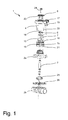
- a manual valve 1 in the form of a diaphragm valve with a multi-part valve main body 2 and a spindle 3 movably arranged therein.
- the valve main body 2 consists in this embodiment of a valve body 2a and a manual valve upper part 2b, which may be screwed together, for example.
- the spindle 3 can be adjusted relative to the valve main body 2 together with the handwheel 4 for actuating the manual valve 1 by means of a handwheel 4 arranged on the spindle 3 in its position. If, as shown, a right-handed thread is used for the adjustment, the manual valve 1 is closed by turning the handwheel 4 clockwise. By turning the handwheel 4 counterclockwise, the manual valve 1 is opened.
- a pressure piece 25 is arranged on the spindle 3, which acts on a membrane 26 in a conventional manner.
- a pressure piece 25 is arranged on the spindle 3, which acts on a membrane 26 in a conventional manner.
- a pressure piece 25 is arranged on the spind
- the handwheel 4 has an integral threaded bushing 10, which is connected via three webs 11 with the handwheel 4.
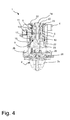
- the spindle 3 is as in particular in the Figs. 3 . 4 . 6 and 7 to recognize screwed into the threaded bush 10.
- the manual valve 1 has a stroke limiter 5, which comprises a stop element in the form of a threaded nut 6 with external thread and a holder in the form of a threaded sleeve 7 with internal thread.
- the nut 6 is as in the Figs. 3 . 4 . 6 and 7 shown screwed into the threaded sleeve 7.
- the threaded sleeve 7 is arranged on the hand valve upper part 2b of the valve main body 2 and has three grooves 12 which are in positive engagement with the three webs 11 of the handwheel. Thus, the threaded sleeve 7 is also rotated upon rotation of the handwheel 4.
- the threaded sleeve 7 is - as will be described below - not in the operating direction of the spindle 3 movable. In other words, although the threaded sleeve 7 can be rotated relative to the valve main body 2, it can not be moved away from or toward it. A translational movement with respect to the valve main body 2 is therefore not possible.
- the position of the threaded nut 6 in the threaded sleeve 7 is changed by screwing in or out.
- the threaded nut 6 is screwed to the upper end of the threaded sleeve 7, so that a maximum stroke can be achieved.
- the nut 6 is as in the Figs. 3 and 4 shown further screwed into the threaded sleeve 7, so that a lower maximum stroke is achieved. If the handwheel 4 is actuated to open the manual valve 1, the handwheel 4 moves away together with the spindle 3 from the valve main body 2. In this case, although the threaded sleeve 7 is rotated, it is not moved away from the valve main body 2.
- the threaded nut 6 can be rotated relative to the threaded sleeve 7 and screwed into this via the actuating element 8 with dissolved rotary connection and in this.
- the actuating element 8 on four projections 13 which engage positively in corresponding recesses of the threaded nut 6.
- the manual valve 1 comprises a closing limit 9, which makes it possible to set the closed position of the spindle 3.
- the rotary joint between actuator 8 and handwheel 4 must also be solved.
- the spindle 3 can then be rotated relative to the handwheel 4.
- the handwheel 4 is first completely screwed in until the lower abutment surface 10b of the threaded bush 10 strikes the hand valve upper part 2b of the valve main body 2. If the handwheel 4 is now rotated further, only the spindle 3 is moved in position relative to the valve main body 2, but no longer the handwheel 4.
- By holding the actuator 8 and turning the handwheel 4 counterclockwise only the handwheel 4 in his Changed position to the valve main body 2, whereby the closed position can be changed in the other direction.
- connection between the spindle 3 and actuator 8 is performed by a two-edge connection, but other connection for power transmission are possible.
- a toothed connection 23 is provided which is no longer in connection with the toothed connection 23 of the handwheel 4 when the actuating element 8 is raised.
- the actuator 8 can be additionally secured by a locking screw 24 which is screwed into the spindle 3.
- the manual valve 1 has a visual display 15, which is covered by the handwheel 4 when the manual valve 1 is completely closed.
- the display 15 is fixedly arranged on the valve main body 2 and the manual valve upper part 2b and is visible when turning the handwheel 4 counterclockwise piece by piece. On the basis of the display 15 can then be determined at a glance, how far the manual valve 1 is open or closed.
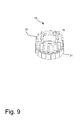
- the display 15 has an at least partially circumferential projection 16, as can be seen in particular Fig. 9 can recognize well.
- This projection 16 fixes the threaded sleeve 7, so that while it is rotatable relative to the valve main body 2, but can not be moved away or away from this. This is necessary for the stroke limitation 5 described above, however, the threaded sleeve 7 could also be fixed via a clamping ring or the like, so that the visual display 15 is not mandatory.
- the display 15 has a plurality of circumferential locking grooves 18. These locking grooves 18 cooperate with a linearly guided on the handwheel 4 locking element 17, which can be moved parallel to the spindle 3. If that Latch member 17 is moved in the direction of the valve main body 2, engages the lower part of the locking element 17 in one of the locking grooves 18 of the display 15, so that rotation of the hand wheel 4 is no longer possible.
- the locking element 17 can be fixed in the engaged position, for example by a lock 19 (see. Fig. 8 ).
- the handwheel 4 has a first marking 20 and the visual display 15 has a second marking 21 at the position of the respective locking groove 18. As soon as the two markings 20, 21 are aligned, the locking element 17 can be inserted into the locking groove 18.
- the manual valve 1 is provided with a plurality of seals 22 between the individual elements.
- the seals 22 are designed as O-rings which sit in corresponding grooves.
- Gaskets 22 are provided between the display 15 and the valve main body 2 and hand valve upper part 2b, between the handwheel 4 and the display 15, between the actuator 8 and the handwheel 4 and between the locking screw 24 and the actuator 8.
- other seals are provided, such as between the valve body 2a and the hand valve upper part 2b.
Landscapes
- Engineering & Computer Science (AREA)
- General Engineering & Computer Science (AREA)
- Mechanical Engineering (AREA)
- Mechanically-Actuated Valves (AREA)
- Indication Of The Valve Opening Or Closing Status (AREA)
Applications Claiming Priority (1)
| Application Number | Priority Date | Filing Date | Title |
|---|---|---|---|
| DE102012109756.9A DE102012109756B4 (de) | 2012-10-12 | 2012-10-12 | Steigendes Handventil mit Hubbegrenzung |
Publications (2)
| Publication Number | Publication Date |
|---|---|
| EP2719932A1 true EP2719932A1 (fr) | 2014-04-16 |
| EP2719932B1 EP2719932B1 (fr) | 2017-01-04 |
Family
ID=49382272
Family Applications (1)
| Application Number | Title | Priority Date | Filing Date |
|---|---|---|---|
| EP13188512.1A Active EP2719932B1 (fr) | 2012-10-12 | 2013-10-14 | Soupape manuelle montante avec limitation de la course |
Country Status (3)
| Country | Link |
|---|---|
| US (1) | US9458948B2 (fr) |
| EP (1) | EP2719932B1 (fr) |
| DE (1) | DE102012109756B4 (fr) |
Cited By (2)
| Publication number | Priority date | Publication date | Assignee | Title |
|---|---|---|---|---|
| CN106885042A (zh) * | 2017-04-17 | 2017-06-23 | 上海阀门五厂有限公司 | 一种可实现上密封的隔膜阀阀盖组件 |
| US11499642B2 (en) | 2020-04-15 | 2022-11-15 | Festo Se & Co. Kg | Pressure actuated valve with shock absorber |
Families Citing this family (15)
| Publication number | Priority date | Publication date | Assignee | Title |
|---|---|---|---|---|
| CN105659011B (zh) * | 2013-08-02 | 2017-12-08 | 株式会社开滋 | 铁路车辆用急速排气阀和铁路车辆的配管系统 |
| KR20160111374A (ko) * | 2013-11-28 | 2016-09-26 | 햄-릿 (이스라엘-캐나다) 엘티디. | 유체의 통과를 제어하고 조절하는 밸브 디바이스 |
| JP6649272B2 (ja) * | 2014-12-11 | 2020-02-19 | 株式会社キッツ | 回転弁と鉄道車両用急速排気弁 |
| CN106090415B (zh) * | 2016-07-26 | 2018-07-13 | 中国石油天然气股份有限公司 | 一种防盗装置及角行程阀门 |
| KR102254663B1 (ko) * | 2017-07-31 | 2021-05-21 | 가부시끼가이샤후지킨 | 가스 공급 시스템 |
| DE102018213711A1 (de) * | 2018-08-15 | 2020-02-20 | Festo Ag & Co. Kg | Ventil |
| DE102018213712B4 (de) * | 2018-08-15 | 2020-10-08 | Festo Se & Co. Kg | Ventilanordnung |
| CA3130063A1 (fr) * | 2019-02-20 | 2020-08-27 | Itt Manufacturing Enterprises Llc | Ensemble diaphragme |
| ES2953306T3 (es) * | 2019-05-29 | 2023-11-10 | Fischer G Rohrleitungssysteme Ag | Puesta en marcha de válvula de diafragma |
| DE102019129059A1 (de) * | 2019-10-28 | 2021-04-29 | Grohe Ag | Ventil für eine Sanitärarmatur mit einem Membranventil und einem einstellbaren Steuerstab |
| JP7448368B2 (ja) * | 2020-02-10 | 2024-03-12 | 株式会社キッツエスシーティー | 手動用ダイヤフラムバルブ |
| KR102461941B1 (ko) * | 2021-08-11 | 2022-11-03 | 안희준 | 컨덕턴스 조절이 가능한 진공밸브 |
| CN115325205A (zh) * | 2022-07-18 | 2022-11-11 | 浙江伯特利科技股份有限公司 | 一种防泄漏密封性好的阀门 |
| CN119103397A (zh) * | 2023-06-09 | 2024-12-10 | 波凯特有限及两合公司 | 用于调节阀杆的阀单元和手轮 |
| CN119103401A (zh) * | 2023-06-09 | 2024-12-10 | 波凯特有限及两合公司 | 具有壳体的阀单元和用于解锁和锁定阀单元的手轮的方法 |
Citations (7)
| Publication number | Priority date | Publication date | Assignee | Title |
|---|---|---|---|---|
| FR1103790A (fr) * | 1954-04-24 | 1955-11-07 | Salvi Ets | Robinet à double réglage, en particulier pour radiateurs de chauffage central |
| FR1482169A (fr) * | 1966-04-06 | 1967-05-26 | Term | Perfectionnements aux vannes à double réglage pour chauffage central et applications analogues |
| US3347270A (en) * | 1965-03-11 | 1967-10-17 | Stile Craft Mfg Inc | Pressure equalizing flow control valve |
| US3565089A (en) * | 1969-01-21 | 1971-02-23 | Elkhart Brass Mfg Co | Valve |
| FR2228996A1 (en) * | 1973-05-11 | 1974-12-06 | Blanchard Ateliers | Manually operated valve with optimum flow indicator - collar on spindle contacts adjustable stop to limit flow |
| EP0387634A1 (fr) * | 1989-03-13 | 1990-09-19 | KSB Aktiengesellschaft | Armature avec limiteur de course |
| EP1257755B1 (fr) | 2000-02-12 | 2005-06-01 | GEMÜ Gebrüder Müller Apparatebau GmbH & Co. KG | Commande manuelle pour organe d'arret |
Family Cites Families (12)
| Publication number | Priority date | Publication date | Assignee | Title |
|---|---|---|---|---|
| US2599286A (en) * | 1946-06-07 | 1952-06-03 | Mason Neilan Regulator Company | Valve position indicator |
| DE1853050U (de) * | 1962-03-28 | 1962-06-07 | Waldenmaier J E H | Membranventil fuer aggressive madien. |
| DE1600813B2 (de) * | 1967-06-29 | 1971-09-02 | Herion Werke KG, 7012 Fellbach | Drosselventil |
| US3712587A (en) * | 1971-05-12 | 1973-01-23 | American La France Inc | Flow restricting valve |
| US3831621A (en) * | 1973-11-19 | 1974-08-27 | Union Brass & Metal Mfg | Rotary slide valve |
| DE3212792C2 (de) * | 1982-04-06 | 1985-04-04 | Klein, Schanzlin & Becker Ag, 6710 Frankenthal | Stellungsanzeiger mit Feststellvorrichtung für Absperrarmaturen |
| DE4302556A1 (de) * | 1993-01-29 | 1994-08-04 | Mueller Apparatebau Gmbh & Co | Membranventil mit Schließhubbegrenzung |
| US5823509A (en) * | 1997-07-11 | 1998-10-20 | Amcast Industrial Corporation | Diaphragm valve with means for adjustably setting the maxium valve opening |
| US6241213B1 (en) * | 2000-03-07 | 2001-06-05 | Itt Manufacturing Enterprises, Inc. | Diaphragm valve |
| JP2006153042A (ja) * | 2004-11-25 | 2006-06-15 | Surpass Kogyo Kk | 流量調節弁 |
| WO2007063635A1 (fr) * | 2005-12-02 | 2007-06-07 | Ckd Corporation | Robinet de reglage de debit |
| DE202010008574U1 (de) * | 2010-09-17 | 2010-12-23 | Sed Flow Control Gmbh | Membranventil mit einer kombinierten Hub-Schließbegrenzung |
-
2012
- 2012-10-12 DE DE102012109756.9A patent/DE102012109756B4/de active Active
-
2013
- 2013-10-14 EP EP13188512.1A patent/EP2719932B1/fr active Active
- 2013-10-15 US US14/054,259 patent/US9458948B2/en active Active
Patent Citations (7)
| Publication number | Priority date | Publication date | Assignee | Title |
|---|---|---|---|---|
| FR1103790A (fr) * | 1954-04-24 | 1955-11-07 | Salvi Ets | Robinet à double réglage, en particulier pour radiateurs de chauffage central |
| US3347270A (en) * | 1965-03-11 | 1967-10-17 | Stile Craft Mfg Inc | Pressure equalizing flow control valve |
| FR1482169A (fr) * | 1966-04-06 | 1967-05-26 | Term | Perfectionnements aux vannes à double réglage pour chauffage central et applications analogues |
| US3565089A (en) * | 1969-01-21 | 1971-02-23 | Elkhart Brass Mfg Co | Valve |
| FR2228996A1 (en) * | 1973-05-11 | 1974-12-06 | Blanchard Ateliers | Manually operated valve with optimum flow indicator - collar on spindle contacts adjustable stop to limit flow |
| EP0387634A1 (fr) * | 1989-03-13 | 1990-09-19 | KSB Aktiengesellschaft | Armature avec limiteur de course |
| EP1257755B1 (fr) | 2000-02-12 | 2005-06-01 | GEMÜ Gebrüder Müller Apparatebau GmbH & Co. KG | Commande manuelle pour organe d'arret |
Cited By (2)
| Publication number | Priority date | Publication date | Assignee | Title |
|---|---|---|---|---|
| CN106885042A (zh) * | 2017-04-17 | 2017-06-23 | 上海阀门五厂有限公司 | 一种可实现上密封的隔膜阀阀盖组件 |
| US11499642B2 (en) | 2020-04-15 | 2022-11-15 | Festo Se & Co. Kg | Pressure actuated valve with shock absorber |
Also Published As
| Publication number | Publication date |
|---|---|
| US20140131607A1 (en) | 2014-05-15 |
| EP2719932B1 (fr) | 2017-01-04 |
| DE102012109756B4 (de) | 2015-01-08 |
| US9458948B2 (en) | 2016-10-04 |
| DE102012109756A1 (de) | 2014-04-17 |
Similar Documents
| Publication | Publication Date | Title |
|---|---|---|
| EP2719932B1 (fr) | Soupape manuelle montante avec limitation de la course | |
| EP2942458B1 (fr) | Système de verrouillage de câble | |
| DE102014111407B4 (de) | Drehschieberventil | |
| EP2616614A1 (fr) | Fermeture à serrage par rotation avec détection de la position de fermeture | |
| EP3084277A1 (fr) | Dispositif à soupape hydraulique | |
| EP3062002A1 (fr) | Partie supérieure de soupape | |
| DE7710413U1 (de) | Vorrichtung zur anzeige der stellung eines betaetigungsgliedes | |
| DE202014101096U1 (de) | Ventiloberteil | |
| EP2041852B1 (fr) | Interrupteur avec un accouplement pour l'organe de commande | |
| DE102012020909B3 (de) | Anordnung zur Drehmomentverstellung für einen Schraubendreher | |
| DE102013105165B4 (de) | Betätigungsvorsatz zur Betätigung eines Tasters und/oder Schalters | |
| EP2354608A1 (fr) | Cartouche de soupape pour une armature sanitaire | |
| DE102008024363B4 (de) | Absperrhahn | |
| DE102019123485A1 (de) | Öffnungs- und Schliessventil | |
| DE202014100716U1 (de) | Handbetätigtes Ventil | |
| EP3001081B1 (fr) | Vanne équerre doté d'un volant à main | |
| DE102018121084B3 (de) | Vorrichtung zur Verstellung einer rotierbaren Frässpindel einer Kantenfräsmaschine und Kantenfräsmaschine | |
| DE69205974T2 (de) | Vorrichtung zum abwechselnden steuern von zwei zusammenwirkenden ventilen, insbesondere von sicherheitsventilen an druckkesseln. | |
| DE102010039678B4 (de) | Stelleinrichtung für ein Ventil | |
| DE9300841U1 (de) | Sanitärarmatur | |
| EP2226541B1 (fr) | Agencement d'actionnement pour armatures sanitaires | |
| DE102010007952B4 (de) | Verschluss für eine Tür eines Gargeräts | |
| DE102020212041B4 (de) | Quetschventil für fließfähige Medien | |
| EP1527295A1 (fr) | Robinet a boisseau spherique a trois voies | |
| DE102006050664B4 (de) | Betätigungsvorrichtung für ein Ventil |
Legal Events
| Date | Code | Title | Description |
|---|---|---|---|
| PUAI | Public reference made under article 153(3) epc to a published international application that has entered the european phase |
Free format text: ORIGINAL CODE: 0009012 |
|
| AK | Designated contracting states |
Kind code of ref document: A1 Designated state(s): AL AT BE BG CH CY CZ DE DK EE ES FI FR GB GR HR HU IE IS IT LI LT LU LV MC MK MT NL NO PL PT RO RS SE SI SK SM TR |
|
| AX | Request for extension of the european patent |
Extension state: BA ME |
|
| 17P | Request for examination filed |
Effective date: 20141013 |
|
| RBV | Designated contracting states (corrected) |
Designated state(s): AL AT BE BG CH CY CZ DE DK EE ES FI FR GB GR HR HU IE IS IT LI LT LU LV MC MK MT NL NO PL PT RO RS SE SI SK SM TR |
|
| REG | Reference to a national code |
Ref country code: DE Ref legal event code: R079 Free format text: PREVIOUS MAIN CLASS: F16K0031500000 Ipc: F16K0017160000 |
|
| RIC1 | Information provided on ipc code assigned before grant |
Ipc: F16K 35/06 20060101ALI20160429BHEP Ipc: F16K 7/12 20060101ALI20160429BHEP Ipc: F16K 31/50 20060101AFI20160429BHEP Ipc: F16K 1/52 20060101ALI20160429BHEP |
|
| GRAP | Despatch of communication of intention to grant a patent |
Free format text: ORIGINAL CODE: EPIDOSNIGR1 |
|
| RIC1 | Information provided on ipc code assigned before grant |
Ipc: F16K 31/50 20060101ALI20160607BHEP Ipc: F16K 7/16 20060101ALI20160607BHEP Ipc: F16K 35/06 20060101ALI20160607BHEP Ipc: F16K 17/16 20060101AFI20160607BHEP Ipc: F16K 7/12 20060101ALI20160607BHEP |
|
| INTG | Intention to grant announced |
Effective date: 20160620 |
|
| GRAS | Grant fee paid |
Free format text: ORIGINAL CODE: EPIDOSNIGR3 |
|
| RBV | Designated contracting states (corrected) |
Designated state(s): AL AT BE BG CH CY CZ DK EE ES FI FR GB GR HR HU IE IS IT LI LT LU LV MC MK MT NL NO PL PT RO RS SE SI SK SM TR |
|
| REG | Reference to a national code |
Ref country code: DE Ref legal event code: R108 |
|
| GRAA | (expected) grant |
Free format text: ORIGINAL CODE: 0009210 |
|
| AK | Designated contracting states |
Kind code of ref document: B1 Designated state(s): AL AT BE BG CH CY CZ DK EE ES FI FR GB GR HR HU IE IS IT LI LT LU LV MC MK MT NL NO PL PT RO RS SE SI SK SM TR |
|
| REG | Reference to a national code |
Ref country code: GB Ref legal event code: FG4D Free format text: NOT ENGLISH |
|
| REG | Reference to a national code |
Ref country code: CH Ref legal event code: EP |
|
| REG | Reference to a national code |
Ref country code: AT Ref legal event code: REF Ref document number: 859582 Country of ref document: AT Kind code of ref document: T Effective date: 20170115 |
|
| REG | Reference to a national code |
Ref country code: IE Ref legal event code: FG4D Free format text: LANGUAGE OF EP DOCUMENT: GERMAN |
|
| REG | Reference to a national code |
Ref country code: CH Ref legal event code: NV Representative=s name: TROESCH SCHEIDEGGER WERNER AG, CH |
|
| REG | Reference to a national code |
Ref country code: LT Ref legal event code: MG4D Ref country code: NL Ref legal event code: MP Effective date: 20170104 |
|
| PG25 | Lapsed in a contracting state [announced via postgrant information from national office to epo] |
Ref country code: NL Free format text: LAPSE BECAUSE OF FAILURE TO SUBMIT A TRANSLATION OF THE DESCRIPTION OR TO PAY THE FEE WITHIN THE PRESCRIBED TIME-LIMIT Effective date: 20170104 |
|
| PG25 | Lapsed in a contracting state [announced via postgrant information from national office to epo] |
Ref country code: FI Free format text: LAPSE BECAUSE OF FAILURE TO SUBMIT A TRANSLATION OF THE DESCRIPTION OR TO PAY THE FEE WITHIN THE PRESCRIBED TIME-LIMIT Effective date: 20170104 Ref country code: LT Free format text: LAPSE BECAUSE OF FAILURE TO SUBMIT A TRANSLATION OF THE DESCRIPTION OR TO PAY THE FEE WITHIN THE PRESCRIBED TIME-LIMIT Effective date: 20170104 Ref country code: GR Free format text: LAPSE BECAUSE OF FAILURE TO SUBMIT A TRANSLATION OF THE DESCRIPTION OR TO PAY THE FEE WITHIN THE PRESCRIBED TIME-LIMIT Effective date: 20170405 Ref country code: NO Free format text: LAPSE BECAUSE OF FAILURE TO SUBMIT A TRANSLATION OF THE DESCRIPTION OR TO PAY THE FEE WITHIN THE PRESCRIBED TIME-LIMIT Effective date: 20170404 Ref country code: HR Free format text: LAPSE BECAUSE OF FAILURE TO SUBMIT A TRANSLATION OF THE DESCRIPTION OR TO PAY THE FEE WITHIN THE PRESCRIBED TIME-LIMIT Effective date: 20170104 Ref country code: IS Free format text: LAPSE BECAUSE OF FAILURE TO SUBMIT A TRANSLATION OF THE DESCRIPTION OR TO PAY THE FEE WITHIN THE PRESCRIBED TIME-LIMIT Effective date: 20170504 |
|
| PG25 | Lapsed in a contracting state [announced via postgrant information from national office to epo] |
Ref country code: SE Free format text: LAPSE BECAUSE OF FAILURE TO SUBMIT A TRANSLATION OF THE DESCRIPTION OR TO PAY THE FEE WITHIN THE PRESCRIBED TIME-LIMIT Effective date: 20170104 Ref country code: LV Free format text: LAPSE BECAUSE OF FAILURE TO SUBMIT A TRANSLATION OF THE DESCRIPTION OR TO PAY THE FEE WITHIN THE PRESCRIBED TIME-LIMIT Effective date: 20170104 Ref country code: ES Free format text: LAPSE BECAUSE OF FAILURE TO SUBMIT A TRANSLATION OF THE DESCRIPTION OR TO PAY THE FEE WITHIN THE PRESCRIBED TIME-LIMIT Effective date: 20170104 Ref country code: PL Free format text: LAPSE BECAUSE OF FAILURE TO SUBMIT A TRANSLATION OF THE DESCRIPTION OR TO PAY THE FEE WITHIN THE PRESCRIBED TIME-LIMIT Effective date: 20170104 Ref country code: PT Free format text: LAPSE BECAUSE OF FAILURE TO SUBMIT A TRANSLATION OF THE DESCRIPTION OR TO PAY THE FEE WITHIN THE PRESCRIBED TIME-LIMIT Effective date: 20170504 Ref country code: BG Free format text: LAPSE BECAUSE OF FAILURE TO SUBMIT A TRANSLATION OF THE DESCRIPTION OR TO PAY THE FEE WITHIN THE PRESCRIBED TIME-LIMIT Effective date: 20170404 Ref country code: RS Free format text: LAPSE BECAUSE OF FAILURE TO SUBMIT A TRANSLATION OF THE DESCRIPTION OR TO PAY THE FEE WITHIN THE PRESCRIBED TIME-LIMIT Effective date: 20170104 |
|
| PG25 | Lapsed in a contracting state [announced via postgrant information from national office to epo] |
Ref country code: SK Free format text: LAPSE BECAUSE OF FAILURE TO SUBMIT A TRANSLATION OF THE DESCRIPTION OR TO PAY THE FEE WITHIN THE PRESCRIBED TIME-LIMIT Effective date: 20170104 Ref country code: CZ Free format text: LAPSE BECAUSE OF FAILURE TO SUBMIT A TRANSLATION OF THE DESCRIPTION OR TO PAY THE FEE WITHIN THE PRESCRIBED TIME-LIMIT Effective date: 20170104 Ref country code: RO Free format text: LAPSE BECAUSE OF FAILURE TO SUBMIT A TRANSLATION OF THE DESCRIPTION OR TO PAY THE FEE WITHIN THE PRESCRIBED TIME-LIMIT Effective date: 20170104 Ref country code: EE Free format text: LAPSE BECAUSE OF FAILURE TO SUBMIT A TRANSLATION OF THE DESCRIPTION OR TO PAY THE FEE WITHIN THE PRESCRIBED TIME-LIMIT Effective date: 20170104 |
|
| PLBE | No opposition filed within time limit |
Free format text: ORIGINAL CODE: 0009261 |
|
| STAA | Information on the status of an ep patent application or granted ep patent |
Free format text: STATUS: NO OPPOSITION FILED WITHIN TIME LIMIT |
|
| PG25 | Lapsed in a contracting state [announced via postgrant information from national office to epo] |
Ref country code: DK Free format text: LAPSE BECAUSE OF FAILURE TO SUBMIT A TRANSLATION OF THE DESCRIPTION OR TO PAY THE FEE WITHIN THE PRESCRIBED TIME-LIMIT Effective date: 20170104 Ref country code: SM Free format text: LAPSE BECAUSE OF FAILURE TO SUBMIT A TRANSLATION OF THE DESCRIPTION OR TO PAY THE FEE WITHIN THE PRESCRIBED TIME-LIMIT Effective date: 20170104 |
|
| 26N | No opposition filed |
Effective date: 20171005 |
|
| PG25 | Lapsed in a contracting state [announced via postgrant information from national office to epo] |
Ref country code: SI Free format text: LAPSE BECAUSE OF FAILURE TO SUBMIT A TRANSLATION OF THE DESCRIPTION OR TO PAY THE FEE WITHIN THE PRESCRIBED TIME-LIMIT Effective date: 20170104 |
|
| PG25 | Lapsed in a contracting state [announced via postgrant information from national office to epo] |
Ref country code: MC Free format text: LAPSE BECAUSE OF FAILURE TO SUBMIT A TRANSLATION OF THE DESCRIPTION OR TO PAY THE FEE WITHIN THE PRESCRIBED TIME-LIMIT Effective date: 20170104 |
|
| GBPC | Gb: european patent ceased through non-payment of renewal fee |
Effective date: 20171014 |
|
| REG | Reference to a national code |
Ref country code: IE Ref legal event code: MM4A |
|
| REG | Reference to a national code |
Ref country code: FR Ref legal event code: ST Effective date: 20180629 |
|
| PG25 | Lapsed in a contracting state [announced via postgrant information from national office to epo] |
Ref country code: LU Free format text: LAPSE BECAUSE OF NON-PAYMENT OF DUE FEES Effective date: 20171014 Ref country code: GB Free format text: LAPSE BECAUSE OF NON-PAYMENT OF DUE FEES Effective date: 20171014 |
|
| REG | Reference to a national code |
Ref country code: BE Ref legal event code: MM Effective date: 20171031 |
|
| PG25 | Lapsed in a contracting state [announced via postgrant information from national office to epo] |
Ref country code: BE Free format text: LAPSE BECAUSE OF NON-PAYMENT OF DUE FEES Effective date: 20171031 Ref country code: FR Free format text: LAPSE BECAUSE OF NON-PAYMENT OF DUE FEES Effective date: 20171031 |
|
| PG25 | Lapsed in a contracting state [announced via postgrant information from national office to epo] |
Ref country code: MT Free format text: LAPSE BECAUSE OF FAILURE TO SUBMIT A TRANSLATION OF THE DESCRIPTION OR TO PAY THE FEE WITHIN THE PRESCRIBED TIME-LIMIT Effective date: 20170104 |
|
| PG25 | Lapsed in a contracting state [announced via postgrant information from national office to epo] |
Ref country code: IE Free format text: LAPSE BECAUSE OF NON-PAYMENT OF DUE FEES Effective date: 20171014 |
|
| PG25 | Lapsed in a contracting state [announced via postgrant information from national office to epo] |
Ref country code: HU Free format text: LAPSE BECAUSE OF FAILURE TO SUBMIT A TRANSLATION OF THE DESCRIPTION OR TO PAY THE FEE WITHIN THE PRESCRIBED TIME-LIMIT; INVALID AB INITIO Effective date: 20131014 |
|
| PG25 | Lapsed in a contracting state [announced via postgrant information from national office to epo] |
Ref country code: CY Free format text: LAPSE BECAUSE OF NON-PAYMENT OF DUE FEES Effective date: 20170104 |
|
| PG25 | Lapsed in a contracting state [announced via postgrant information from national office to epo] |
Ref country code: MK Free format text: LAPSE BECAUSE OF FAILURE TO SUBMIT A TRANSLATION OF THE DESCRIPTION OR TO PAY THE FEE WITHIN THE PRESCRIBED TIME-LIMIT Effective date: 20170104 |
|
| REG | Reference to a national code |
Ref country code: AT Ref legal event code: MM01 Ref document number: 859582 Country of ref document: AT Kind code of ref document: T Effective date: 20181014 |
|
| PG25 | Lapsed in a contracting state [announced via postgrant information from national office to epo] |
Ref country code: AT Free format text: LAPSE BECAUSE OF NON-PAYMENT OF DUE FEES Effective date: 20181014 |
|
| PG25 | Lapsed in a contracting state [announced via postgrant information from national office to epo] |
Ref country code: TR Free format text: LAPSE BECAUSE OF FAILURE TO SUBMIT A TRANSLATION OF THE DESCRIPTION OR TO PAY THE FEE WITHIN THE PRESCRIBED TIME-LIMIT Effective date: 20170104 |
|
| PG25 | Lapsed in a contracting state [announced via postgrant information from national office to epo] |
Ref country code: AL Free format text: LAPSE BECAUSE OF FAILURE TO SUBMIT A TRANSLATION OF THE DESCRIPTION OR TO PAY THE FEE WITHIN THE PRESCRIBED TIME-LIMIT Effective date: 20170104 |
|
| REG | Reference to a national code |
Ref country code: CH Ref legal event code: U11 Free format text: ST27 STATUS EVENT CODE: U-0-0-U10-U11 (AS PROVIDED BY THE NATIONAL OFFICE) Effective date: 20251120 |
|
| PGFP | Annual fee paid to national office [announced via postgrant information from national office to epo] |
Ref country code: IT Payment date: 20251030 Year of fee payment: 13 |
|
| PGFP | Annual fee paid to national office [announced via postgrant information from national office to epo] |
Ref country code: CH Payment date: 20251120 Year of fee payment: 13 |