EP2719956A1 - Procédé destiné à tempérer un bâtiment et à préparer de l'eau chauffée - Google Patents
Procédé destiné à tempérer un bâtiment et à préparer de l'eau chauffée Download PDFInfo
- Publication number
- EP2719956A1 EP2719956A1 EP12187790.6A EP12187790A EP2719956A1 EP 2719956 A1 EP2719956 A1 EP 2719956A1 EP 12187790 A EP12187790 A EP 12187790A EP 2719956 A1 EP2719956 A1 EP 2719956A1
- Authority
- EP
- European Patent Office
- Prior art keywords
- heat
- coolant
- transfer medium
- heat transfer
- heated
- Prior art date
- Legal status (The legal status is an assumption and is not a legal conclusion. Google has not performed a legal analysis and makes no representation as to the accuracy of the status listed.)
- Withdrawn
Links
- 238000010438 heat treatment Methods 0.000 title claims abstract description 87
- XLYOFNOQVPJJNP-UHFFFAOYSA-N water Substances O XLYOFNOQVPJJNP-UHFFFAOYSA-N 0.000 title claims abstract description 79
- 238000001816 cooling Methods 0.000 title claims abstract description 67
- 238000000034 method Methods 0.000 title claims abstract description 21
- 239000002826 coolant Substances 0.000 claims description 109
- 238000009423 ventilation Methods 0.000 claims description 37
- 239000003651 drinking water Substances 0.000 claims description 12
- 235000020188 drinking water Nutrition 0.000 claims description 12
- 238000005086 pumping Methods 0.000 claims description 7
- 239000003507 refrigerant Substances 0.000 claims description 7
- 239000008236 heating water Substances 0.000 claims description 5
- 230000002441 reversible effect Effects 0.000 claims description 5
- 238000005496 tempering Methods 0.000 claims description 4
- 239000000872 buffer Substances 0.000 description 11
- 238000001035 drying Methods 0.000 description 7
- CURLTUGMZLYLDI-UHFFFAOYSA-N Carbon dioxide Chemical compound O=C=O CURLTUGMZLYLDI-UHFFFAOYSA-N 0.000 description 4
- 230000001276 controlling effect Effects 0.000 description 4
- 229910002092 carbon dioxide Inorganic materials 0.000 description 2
- 239000001569 carbon dioxide Substances 0.000 description 2
- 230000005855 radiation Effects 0.000 description 2
- 238000010521 absorption reaction Methods 0.000 description 1
- 230000003213 activating effect Effects 0.000 description 1
- 230000002457 bidirectional effect Effects 0.000 description 1
- 238000000605 extraction Methods 0.000 description 1
- 239000012530 fluid Substances 0.000 description 1
- 238000005338 heat storage Methods 0.000 description 1
- 238000009413 insulation Methods 0.000 description 1
- 238000005399 mechanical ventilation Methods 0.000 description 1
- 238000002156 mixing Methods 0.000 description 1
- 238000010248 power generation Methods 0.000 description 1
- 230000001105 regulatory effect Effects 0.000 description 1
- 230000000630 rising effect Effects 0.000 description 1
- 239000012536 storage buffer Substances 0.000 description 1
Images


Classifications
-
- F—MECHANICAL ENGINEERING; LIGHTING; HEATING; WEAPONS; BLASTING
- F25—REFRIGERATION OR COOLING; COMBINED HEATING AND REFRIGERATION SYSTEMS; HEAT PUMP SYSTEMS; MANUFACTURE OR STORAGE OF ICE; LIQUEFACTION SOLIDIFICATION OF GASES
- F25B—REFRIGERATION MACHINES, PLANTS OR SYSTEMS; COMBINED HEATING AND REFRIGERATION SYSTEMS; HEAT PUMP SYSTEMS
- F25B13/00—Compression machines, plants or systems, with reversible cycle
-
- F—MECHANICAL ENGINEERING; LIGHTING; HEATING; WEAPONS; BLASTING
- F24—HEATING; RANGES; VENTILATING
- F24D—DOMESTIC- OR SPACE-HEATING SYSTEMS, e.g. CENTRAL HEATING SYSTEMS; DOMESTIC HOT-WATER SUPPLY SYSTEMS; ELEMENTS OR COMPONENTS THEREFOR
- F24D11/00—Central heating systems using heat accumulated in storage masses
- F24D11/02—Central heating systems using heat accumulated in storage masses using heat pumps
- F24D11/0214—Central heating systems using heat accumulated in storage masses using heat pumps water heating system
- F24D11/0235—Central heating systems using heat accumulated in storage masses using heat pumps water heating system with recuperation of waste energy
- F24D11/0242—Central heating systems using heat accumulated in storage masses using heat pumps water heating system with recuperation of waste energy contained in exhausted air
-
- F—MECHANICAL ENGINEERING; LIGHTING; HEATING; WEAPONS; BLASTING
- F24—HEATING; RANGES; VENTILATING
- F24D—DOMESTIC- OR SPACE-HEATING SYSTEMS, e.g. CENTRAL HEATING SYSTEMS; DOMESTIC HOT-WATER SUPPLY SYSTEMS; ELEMENTS OR COMPONENTS THEREFOR
- F24D17/00—Domestic hot-water supply systems
- F24D17/0005—Domestic hot-water supply systems using recuperation of waste heat
- F24D17/001—Domestic hot-water supply systems using recuperation of waste heat with accumulation of heated water
-
- F—MECHANICAL ENGINEERING; LIGHTING; HEATING; WEAPONS; BLASTING
- F24—HEATING; RANGES; VENTILATING
- F24D—DOMESTIC- OR SPACE-HEATING SYSTEMS, e.g. CENTRAL HEATING SYSTEMS; DOMESTIC HOT-WATER SUPPLY SYSTEMS; ELEMENTS OR COMPONENTS THEREFOR
- F24D17/00—Domestic hot-water supply systems
- F24D17/02—Domestic hot-water supply systems using heat pumps
-
- F—MECHANICAL ENGINEERING; LIGHTING; HEATING; WEAPONS; BLASTING
- F24—HEATING; RANGES; VENTILATING
- F24F—AIR-CONDITIONING; AIR-HUMIDIFICATION; VENTILATION; USE OF AIR CURRENTS FOR SCREENING
- F24F5/00—Air-conditioning systems or apparatus not covered by F24F1/00 or F24F3/00, e.g. using solar heat or combined with household units such as an oven or water heater
- F24F5/0096—Air-conditioning systems or apparatus not covered by F24F1/00 or F24F3/00, e.g. using solar heat or combined with household units such as an oven or water heater combined with domestic apparatus
-
- F—MECHANICAL ENGINEERING; LIGHTING; HEATING; WEAPONS; BLASTING
- F24—HEATING; RANGES; VENTILATING
- F24D—DOMESTIC- OR SPACE-HEATING SYSTEMS, e.g. CENTRAL HEATING SYSTEMS; DOMESTIC HOT-WATER SUPPLY SYSTEMS; ELEMENTS OR COMPONENTS THEREFOR
- F24D2200/00—Heat sources or energy sources
- F24D2200/12—Heat pump
-
- F—MECHANICAL ENGINEERING; LIGHTING; HEATING; WEAPONS; BLASTING
- F24—HEATING; RANGES; VENTILATING
- F24D—DOMESTIC- OR SPACE-HEATING SYSTEMS, e.g. CENTRAL HEATING SYSTEMS; DOMESTIC HOT-WATER SUPPLY SYSTEMS; ELEMENTS OR COMPONENTS THEREFOR
- F24D2200/00—Heat sources or energy sources
- F24D2200/14—Solar energy
-
- F—MECHANICAL ENGINEERING; LIGHTING; HEATING; WEAPONS; BLASTING
- F24—HEATING; RANGES; VENTILATING
- F24D—DOMESTIC- OR SPACE-HEATING SYSTEMS, e.g. CENTRAL HEATING SYSTEMS; DOMESTIC HOT-WATER SUPPLY SYSTEMS; ELEMENTS OR COMPONENTS THEREFOR
- F24D2200/00—Heat sources or energy sources
- F24D2200/16—Waste heat
- F24D2200/31—Air conditioning systems
-
- F—MECHANICAL ENGINEERING; LIGHTING; HEATING; WEAPONS; BLASTING
- F25—REFRIGERATION OR COOLING; COMBINED HEATING AND REFRIGERATION SYSTEMS; HEAT PUMP SYSTEMS; MANUFACTURE OR STORAGE OF ICE; LIQUEFACTION SOLIDIFICATION OF GASES
- F25B—REFRIGERATION MACHINES, PLANTS OR SYSTEMS; COMBINED HEATING AND REFRIGERATION SYSTEMS; HEAT PUMP SYSTEMS
- F25B2313/00—Compression machines, plants or systems with reversible cycle not otherwise provided for
- F25B2313/021—Indoor unit or outdoor unit with auxiliary heat exchanger not forming part of the indoor or outdoor unit
-
- F—MECHANICAL ENGINEERING; LIGHTING; HEATING; WEAPONS; BLASTING
- F25—REFRIGERATION OR COOLING; COMBINED HEATING AND REFRIGERATION SYSTEMS; HEAT PUMP SYSTEMS; MANUFACTURE OR STORAGE OF ICE; LIQUEFACTION SOLIDIFICATION OF GASES
- F25B—REFRIGERATION MACHINES, PLANTS OR SYSTEMS; COMBINED HEATING AND REFRIGERATION SYSTEMS; HEAT PUMP SYSTEMS
- F25B2600/00—Control issues
- F25B2600/02—Compressor control
- F25B2600/025—Compressor control by controlling speed
- F25B2600/0253—Compressor control by controlling speed with variable speed
-
- F—MECHANICAL ENGINEERING; LIGHTING; HEATING; WEAPONS; BLASTING
- F25—REFRIGERATION OR COOLING; COMBINED HEATING AND REFRIGERATION SYSTEMS; HEAT PUMP SYSTEMS; MANUFACTURE OR STORAGE OF ICE; LIQUEFACTION SOLIDIFICATION OF GASES
- F25B—REFRIGERATION MACHINES, PLANTS OR SYSTEMS; COMBINED HEATING AND REFRIGERATION SYSTEMS; HEAT PUMP SYSTEMS
- F25B2700/00—Sensing or detecting of parameters; Sensors therefor
- F25B2700/19—Pressures
- F25B2700/193—Pressures of the compressor
- F25B2700/1931—Discharge pressures
-
- F—MECHANICAL ENGINEERING; LIGHTING; HEATING; WEAPONS; BLASTING
- F25—REFRIGERATION OR COOLING; COMBINED HEATING AND REFRIGERATION SYSTEMS; HEAT PUMP SYSTEMS; MANUFACTURE OR STORAGE OF ICE; LIQUEFACTION SOLIDIFICATION OF GASES
- F25B—REFRIGERATION MACHINES, PLANTS OR SYSTEMS; COMBINED HEATING AND REFRIGERATION SYSTEMS; HEAT PUMP SYSTEMS
- F25B2700/00—Sensing or detecting of parameters; Sensors therefor
- F25B2700/19—Pressures
- F25B2700/193—Pressures of the compressor
- F25B2700/1933—Suction pressures
-
- F—MECHANICAL ENGINEERING; LIGHTING; HEATING; WEAPONS; BLASTING
- F25—REFRIGERATION OR COOLING; COMBINED HEATING AND REFRIGERATION SYSTEMS; HEAT PUMP SYSTEMS; MANUFACTURE OR STORAGE OF ICE; LIQUEFACTION SOLIDIFICATION OF GASES
- F25B—REFRIGERATION MACHINES, PLANTS OR SYSTEMS; COMBINED HEATING AND REFRIGERATION SYSTEMS; HEAT PUMP SYSTEMS
- F25B2700/00—Sensing or detecting of parameters; Sensors therefor
- F25B2700/21—Temperatures
- F25B2700/2115—Temperatures of a compressor or the drive means therefor
- F25B2700/21151—Temperatures of a compressor or the drive means therefor at the suction side of the compressor
-
- F—MECHANICAL ENGINEERING; LIGHTING; HEATING; WEAPONS; BLASTING
- F25—REFRIGERATION OR COOLING; COMBINED HEATING AND REFRIGERATION SYSTEMS; HEAT PUMP SYSTEMS; MANUFACTURE OR STORAGE OF ICE; LIQUEFACTION SOLIDIFICATION OF GASES
- F25B—REFRIGERATION MACHINES, PLANTS OR SYSTEMS; COMBINED HEATING AND REFRIGERATION SYSTEMS; HEAT PUMP SYSTEMS
- F25B2700/00—Sensing or detecting of parameters; Sensors therefor
- F25B2700/21—Temperatures
- F25B2700/2115—Temperatures of a compressor or the drive means therefor
- F25B2700/21152—Temperatures of a compressor or the drive means therefor at the discharge side of the compressor
-
- Y—GENERAL TAGGING OF NEW TECHNOLOGICAL DEVELOPMENTS; GENERAL TAGGING OF CROSS-SECTIONAL TECHNOLOGIES SPANNING OVER SEVERAL SECTIONS OF THE IPC; TECHNICAL SUBJECTS COVERED BY FORMER USPC CROSS-REFERENCE ART COLLECTIONS [XRACs] AND DIGESTS
- Y02—TECHNOLOGIES OR APPLICATIONS FOR MITIGATION OR ADAPTATION AGAINST CLIMATE CHANGE
- Y02B—CLIMATE CHANGE MITIGATION TECHNOLOGIES RELATED TO BUILDINGS, e.g. HOUSING, HOUSE APPLIANCES OR RELATED END-USER APPLICATIONS
- Y02B10/00—Integration of renewable energy sources in buildings
- Y02B10/20—Solar thermal
-
- Y—GENERAL TAGGING OF NEW TECHNOLOGICAL DEVELOPMENTS; GENERAL TAGGING OF CROSS-SECTIONAL TECHNOLOGIES SPANNING OVER SEVERAL SECTIONS OF THE IPC; TECHNICAL SUBJECTS COVERED BY FORMER USPC CROSS-REFERENCE ART COLLECTIONS [XRACs] AND DIGESTS
- Y02—TECHNOLOGIES OR APPLICATIONS FOR MITIGATION OR ADAPTATION AGAINST CLIMATE CHANGE
- Y02B—CLIMATE CHANGE MITIGATION TECHNOLOGIES RELATED TO BUILDINGS, e.g. HOUSING, HOUSE APPLIANCES OR RELATED END-USER APPLICATIONS
- Y02B10/00—Integration of renewable energy sources in buildings
- Y02B10/70—Hybrid systems, e.g. uninterruptible or back-up power supplies integrating renewable energies
-
- Y—GENERAL TAGGING OF NEW TECHNOLOGICAL DEVELOPMENTS; GENERAL TAGGING OF CROSS-SECTIONAL TECHNOLOGIES SPANNING OVER SEVERAL SECTIONS OF THE IPC; TECHNICAL SUBJECTS COVERED BY FORMER USPC CROSS-REFERENCE ART COLLECTIONS [XRACs] AND DIGESTS
- Y02—TECHNOLOGIES OR APPLICATIONS FOR MITIGATION OR ADAPTATION AGAINST CLIMATE CHANGE
- Y02B—CLIMATE CHANGE MITIGATION TECHNOLOGIES RELATED TO BUILDINGS, e.g. HOUSING, HOUSE APPLIANCES OR RELATED END-USER APPLICATIONS
- Y02B30/00—Energy efficient heating, ventilation or air conditioning [HVAC]
- Y02B30/18—Domestic hot-water supply systems using recuperated or waste heat
-
- Y—GENERAL TAGGING OF NEW TECHNOLOGICAL DEVELOPMENTS; GENERAL TAGGING OF CROSS-SECTIONAL TECHNOLOGIES SPANNING OVER SEVERAL SECTIONS OF THE IPC; TECHNICAL SUBJECTS COVERED BY FORMER USPC CROSS-REFERENCE ART COLLECTIONS [XRACs] AND DIGESTS
- Y02—TECHNOLOGIES OR APPLICATIONS FOR MITIGATION OR ADAPTATION AGAINST CLIMATE CHANGE
- Y02B—CLIMATE CHANGE MITIGATION TECHNOLOGIES RELATED TO BUILDINGS, e.g. HOUSING, HOUSE APPLIANCES OR RELATED END-USER APPLICATIONS
- Y02B30/00—Energy efficient heating, ventilation or air conditioning [HVAC]
- Y02B30/52—Heat recovery pumps, i.e. heat pump based systems or units able to transfer the thermal energy from one area of the premises or part of the facilities to a different one, improving the overall efficiency
-
- Y—GENERAL TAGGING OF NEW TECHNOLOGICAL DEVELOPMENTS; GENERAL TAGGING OF CROSS-SECTIONAL TECHNOLOGIES SPANNING OVER SEVERAL SECTIONS OF THE IPC; TECHNICAL SUBJECTS COVERED BY FORMER USPC CROSS-REFERENCE ART COLLECTIONS [XRACs] AND DIGESTS
- Y02—TECHNOLOGIES OR APPLICATIONS FOR MITIGATION OR ADAPTATION AGAINST CLIMATE CHANGE
- Y02B—CLIMATE CHANGE MITIGATION TECHNOLOGIES RELATED TO BUILDINGS, e.g. HOUSING, HOUSE APPLIANCES OR RELATED END-USER APPLICATIONS
- Y02B30/00—Energy efficient heating, ventilation or air conditioning [HVAC]
- Y02B30/70—Efficient control or regulation technologies, e.g. for control of refrigerant flow, motor or heating
Definitions
- the invention relates to a method for controlling the temperature of a building and to provide heated water, wherein a heat pump with a ventilation module and a hot water tank is used. Furthermore, the invention relates to an energy system for buildings with a heat pump, a hot water tank and a ventilation module.
- the invention is therefore based on the technical problem of specifying a method of the type mentioned, which is characterized by high efficiency, flexible usability and easy controllability. Likewise, the invention is based on the technical problem of specifying a device for carrying out the method.
- the invention teaches a method for controlling the temperature of a building and for providing heated drinking water and / or heating water, wherein a heat pump is used with a ventilation module and a hot water tank, wherein sucked with the ventilation module secondary air from a room of the building and is heated in a heating operation by the heat pump or wherein the ventilation module secondary air sucked out of the room and cooled in a cooling operation of the heat pump, wherein the heated secondary air or the cooled secondary air is fed back into the room, wherein the heating operation in the cooling operation reversible is switchable and wherein in the heating mode and in the cooling operation, a heat transfer medium is heated with the heat pump, which heat transfer medium, the drinking water is heated and / or which heat transfer medium is used as a heated heating water preferably for controlling the temperature of the room.
- the secondary air is taken from a drying room, then tempered by the heat pump and then returned to the drying room. It is possible that the drying space from which the secondary air is extracted is different from the drying space to which the secondary air is returned. It is recommended that a switching pulse from a ventilation control can be switched from heating mode to cooling mode and vice versa.
- the building or the room has a sensor, which sensor preferably monitors a temperature and / or humidity and / or carbon dioxide content and / or presence of persons (absence function) in the room or in the building. Appropriately, the sensor activates the heating operation, when a predetermined temperature of the sensor in the room or in the building is reached.
- the cooling operation when a predetermined temperature sensor in the room or in the building is exceeded.
- the sensor is arranged in an exhaust air flow in the flow direction of the exhaust air in front of a continuous air heat exchanger.
- the exhaust air leaving the continuous heat exchanger is discharged as exhaust air into the atmosphere and / or fed to the source side of the heat pump.
- the sensor is a component of the ventilation control. It is recommended that the ventilation control be used to set a secondary air flow rate.
- an outside air is used as a heat source for the heat pump.
- the outside air is sucked outside the building and supplied to the source side of the heat pump.
- the heat pump It is possible for the heat pump to be supplied with room air extracted from the room on the source side.
- the source side of the heat pump is supplied from the room extracted exhaust air when the exhaust air is sucked out of a wet room.
- outside air fresh air
- a volumetric flow rate of the exhaust air led out of the building is exactly the same or substantially as large as a volumetric flow of the outside air (fresh air) which is preferably introduced into the building for ventilation.
- a heat energy of the exhaust air is transferred to the sucked outside air, especially for tempering the outside air, preferably in the continuous heat exchanger, before the sucked outside air is blown as supply air into the building or in the room of the building.
- the sucked outside air after the Humidification is moistened with the proviso that the moisture content of the exhaust air extracted from the room corresponds or substantially corresponds to the moisture content of the supply air blown into the room.
- the moisture content of the exhaust air extracted from the room or from the building is transferred to the outside air during the temperature control of the drawn-in outside air. It has been found to be particularly advantageous that the ventilation of the room is carried out permanently or without interruption, wherein preferably the volume flow of the exhaust air and the sucked outside air is adjustable.
- the extraction of the secondary air from the room and the return of the secondary air into the room are performed separately and / or independently of the ventilation of the room with fresh air or supply air.
- a temperature adjustment of the exhaust air takes place in an advantageous manner essentially and preferably exclusively via the heating or cooling of the secondary air.
- the heating of the heat transfer medium is particularly preferably independent of whether the secondary air is heated with the heat pump (heating operation) or whether the secondary air is cooled by the heat pump (cooling operation).
- the heating of the heat transfer medium is independent of a mode of operation of the heat pump.
- the method according to the invention is used in a low energy house and / or passive house.
- the heated by the heat pump heat transfer medium is introduced into the hot water tank and / or fed to a heating element.
- the heat transfer medium is water or buffer water.
- the heated, preferably in The buffer water received in the hot water tank is used, for example, as heating water for the heating element, which heating element is preferably designed as a surface heating element. It is possible that the heating of the buffer water takes place depending on a need for hot water (requirement). In principle, it is possible that the heating of the buffer water over preferably unchangeable, fixed specifications (fixed value setting).
- the heat transfer medium heated by the heat pump is supplied to a arranged in the hot water tank hot water heat exchanger, with the hot water heat exchanger heat of the heat transfer medium is transferred to preferably absorbed in the hot water storage buffer water.
- at least one drinking water heat exchanger is arranged in the hot water tank, with the drinking water heat exchanger heat of the heat transfer medium to be heated to drinking water (service water) is transmitted.
- the drinking water is heated with the drinking water heat exchanger in the hot water tank in a continuous flow principle.
- a heat exchanger with which heat exchanger heat is transferred from the heat pump to the heat transfer medium, flows through in the heating operation and in cooling operation in the same direction of the heat transfer medium.
- a primary side of the heat exchanger is flowed through by a heated coolant to the heat pump.
- a secondary side of the heat exchanger is flowed through by the heat transfer medium within the scope of the invention. It has been proven that the coolant flowing through the primary side of the heat exchanger and that the heat transfer medium flowing through the secondary side of the heat exchanger preferably flow through the heat exchanger in the same directions, independently of the operating mode of the heat pump.
- the heat pump from the heating operation In the cooling mode or switched from the cooling mode to the heating mode, preferably the flow direction of the coolant in the primary side of the heat exchanger and the flow direction of the heat transfer medium in the secondary side of the heat exchanger is maintained. In this way it is permanently ensured that the heat exchanger is operated with a high degree of efficiency.
- the heat transfer medium is circulated in a heat transfer medium circuit. It is recommended that heat taken up by the heat transfer medium in the heat exchanger is conveyed to the hot water heat exchanger arranged in the hot water storage tank. In principle, it is possible to form the heat transfer medium circulation pump-free.
- the heating element and / or the hot water storage is connected in series with the heat exchanger. EmpfohleneIER flows through the heat transfer medium after heating in the heat exchanger, the pumping device and then the hot water tank and / or the heating element.
- the hot water tank and the heating element are connected in parallel, so that the heat transfer medium flows through the surface heating element and the hot water tank each. To reduce the flow temperature of the hot water tank and / or the heating element, it is possible that the hot water tank and / or the heating element heat transfer medium is mixed, which heat transfer medium has flowed through the heating element.
- the heat pump has a coolant circuit with a condenser (condenser) and an evaporator, wherein when switching from the heating mode to the cooling mode or from the cooling mode to the heating mode, a power of a compressor (compressor) of the heat pump is reduced, which compressor is a coolant in the coolant circuit of Heat pump compressed or pumped.
- a power of the compressor (compressor) when switching from heating to cooling operation or from cooling operation in the heating operation, pressure surges are avoided.
- a speed of the compressor is reduced to preferably lower a pressure level of the coolant in the coolant circuit.
- at least one pressure sensor is integrated into the coolant circuit.
- the coolant circuit on two pressure sensors, wherein a first pressure sensor on the pressure side of the compressor and a second pressure sensor is arranged on the suction side of the compressor.
- a first pressure sensor on the pressure side of the compressor and a second pressure sensor is arranged on the suction side of the compressor.
- the compressor or compressor is turned off when the pressure-side and / or suction-side pressure sensor detects a lying above a predetermined threshold pressure in the coolant circuit.
- the evaporator has a fan with which fan the outside air (fresh air) and / or exhaust air can be fed to the evaporator.
- the fan is activated when, for example, in heating operation, the pressure in the evaporator or on the suction side of the compressor is greater than 5 bar.
- the fan is activated in heating mode when the pressure in the evaporator or on the pressure side of the compressor is at least 35 bar. If the pressure in the evaporator is less than 5 bar in heating mode or less than 35 bar in cooling mode, the fan is deactivated. It is recommended that at least one or in each case a temperature sensor is arranged in the coolant circuit on the pressure side of the compressor and / or the suction side of the compressor. It is recommended that the compressor be shut off when the temperature sensor detects a coolant temperature, which coolant temperature is above a predetermined threshold.
- the temperature sensor or the temperature sensors are particularly preferably designed as NTC (negative temperature coefficient) temperature sensor / temperature sensors.
- the coolant in the coolant circuit in the heating operation in the condenser heat to a medium to be tempered, preferably to the secondary air and / or water, wherein the coolant in the heating operation in the evaporator heat from the environment, preferably from the exhaust air and / or outside air , picks up.
- the heat transfer medium is heated with the heat exchanger in the heating mode, wherein heat from the coolant is preferably transferred to the heat transfer medium in the heat exchanger.
- the coolant in the heating operation first flows through the compressor and then as a compressed and heated coolant, preferably the heat exchanger and, following the heat exchanger, preferably the condenser.
- the coolant in the condenser releases the heat stored in the compressed coolant to the secondary air extracted from the space.
- the coolant flows from the condenser to an evaporator in which the refrigerant evaporates while cooling.
- the evaporator heat, for example, transferred from the outside air and / or exhaust air to the expediently relaxed coolant.
- the coolant transfers heat to the heat transfer medium in a cooling downstream of the compressor in the flow direction of the coolant, wherein the coolant in the condenser receives heat from the building, preferably from the extracted secondary air from the building.
- the coolant is compressed or compressed in the cooling operation in the compressor, flows through the heat exchanger and is then passed through the evaporator.
- the condenser is arranged in the cooling operation behind the evaporator, of which Condenser from the preferably relaxed coolant is supplied to the compressor.
- heat of the coolant is discharged via the evaporator, for example to the outside air.
- the condenser be operated as an evaporator in cooling mode.
- the evaporator is used as a condenser in the cooling mode. It is possible to heat and / or defrost the evaporator during cooling operation.
- the evaporator has a temperature sensor, preferably designed as an NTC temperature sensor, with which the temperature and, advantageously, icing of the evaporator can be measured.
- the invention relates to solving the technical problem, an energy system for buildings with a heat pump, a hot water tank and a ventilation module, with the ventilation module, a secondary air from a room of the building to the heat pump can be conveyed, the secondary air to the heat pump in a heating operation of the heat pump can be heated or cooled in a cooling operation of the heat pump, wherein the heated secondary air or cooled secondary air to the room of the building through the ventilation module can be supplied with the heat pump, a heat transfer medium in the heating mode and in the cooling mode is heated, which heated heat transfer medium in the hot water tank can be introduced and wherein the heat pump has an adjusting device, with which adjusting device reversible from the heating operation of the heat pump in the cooling operation of the heat pump is switchable.
- the heat transfer medium is heated or can be heated in the heating mode and in the cooling mode of the heat pump. It is within the scope of the invention that the provision of heated heat transfer medium is decoupled from the temperature control of the secondary air.
- the ventilation module has at least one secondary air fan and / or at least one secondary air filter. It is recommended that the secondary air module is preferably separable from the heat pump or a condenser of the heat pump by mechanical ventilation flaps. It is recommended that the energy system has a fresh air module, via which fresh air module to the room of the building or the building fresh air or outdoor air can be supplied as supply air. According to one embodiment, the fresh air module preferably has a ventilating fan.
- the fresh air module has a vent fan, with which vent fan exhaust air from the room of the building or from the building is sucked.
- the fresh air module has a heat exchanger, for example a rotary heat exchanger. Empfohlenelitz heat from the exhaust air is transferred with the heat exchanger to the intake outside air, which sucked outside air is introduced after the heat transfer as tempered supply air in the room of the building or in the building.
- the fresh air module particularly preferably has a separate air duct system, which air duct system differs from a duct system, in which duct system the secondary air is conveyed from the room or from the building to the heat pump and from the heat pump back into the room or into the building.
- the ventilation fan is controlled independently of the secondary air fan or is controllable.
- the secondary air fan and the fresh air fan are operated with the proviso that a total volume flow, which total volume flow is composed of a volume flow of the secondary air and a volume flow of the supply air, preferably 300 to 800 m 3 per hour. It is recommended that, in a heating operation of the heat pump or cooling operation of the heat pump, the ratio of a secondary air volume flow to an exhaust air volume flow is about 8: 1 to 2: 1 and preferably about 7: 1 to 3: 1. In principle, it is possible that only supply air is introduced into the room or into the building. It is recommended that the volume flow of the supply air introduced into the room is approximately 100 to 250 m 3 per hour.
- the heat pump has a coolant circuit with a compressor, a condenser and an evaporator, wherein the coolant is compressible with the compressor, wherein a heat exchanger is integrated into the coolant circuit in the flow direction of the coolant behind the compressor, in which heat exchanger heat from the coolant is transferable to the heat transfer medium.
- the heat exchanger is designed as a plate heat exchanger.
- the heat exchanger is advantageously flowed through by the coolant.
- the heat exchanger on the secondary side is particularly preferably flowed through by buffer water. It is recommended that a rated capacity of the compressor be fully or substantially fully available when heated water is provided.
- the secondary air fan is activated together with the compressor. It is possible that at least a part and more preferably only a part of the power of the secondary air fan and / or the ventilation fan retrieved will / will be when the full rated capacity of the compressor is requested to produce hot water.
- a secondary air flow and / or exhaust air flow or exhaust air flow is generated, wherein the secondary air flow and / or exhaust air flow or exhaust air flow can be fed to the source side of the heat pump.
- the heat pump can be operated with high efficiency, since the source side, a working fluid is available at a high temperature. It is recommended that the secondary air fan and / or the ventilation fan are operable only with a part of the rated power of the secondary air fan or the ventilation fan, if preferably in the cooling operation of the heat pump heated water is prepared.
- a pump device is provided with which pumping device the heat transfer medium can be pumped in a heat transfer medium circuit.
- the heat transfer medium circuit has recommended about a line system with the heat exchanger, preferably a hot water heat exchanger, expediently the pumping device and preferably a heating element.
- the heating element is, for example, a surface heating element.
- Heat is provided by the heat pump to the heat transfer medium via the heat exchanger.
- a heat transfer from the heat transfer medium to water for example, to drinking water.
- the hot water heat exchanger is designed as lying in the hot water tank heat exchanger.
- the pumping device is designed as an efficiency pump.
- the adjusting device is designed as a multi-way valve, with which multi-way valve, a coolant flow in the coolant circuit with the It can be guided or adjusted that the compressed coolant is then first fed to the heat exchanger and, in a heating position of the adjusting device, subsequently to the condenser or, in a cooling position of the adjusting device, to the evaporator.
- the actuator is in heating in the heating position or cooling mode in the cooling position. From the heating position of the adjusting device can be reversibly reversed in the cooling position in the invention.
- the coolant circuit preferably includes the compressor, the heat exchanger, the actuator, the condenser, preferably an expansion unit and the evaporator.
- the adjusting device In heating mode, the adjusting device preferably connects the heat exchanger with the condenser and the evaporator with a suction side of the compressor. It is recommended that in cooling mode, the actuator connects the heat exchanger with the evaporator and the condenser with the suction side of the compressor.
- the expansion unit is expediently positioned between the condenser and the evaporator in the coolant circuit and is preferably bidirectionally permeable or operable. According to one embodiment, the expansion unit has at least one filter drier and at least one expansion valve. It has been proven that the expansion valve is arranged between two filter driers. Both the expansion valve and the filter drier or filter driers are each intended for bidirectional operation.
- the refrigerant compressed by the compressor is first conveyed to the heat exchanger, in which heat exchanger at least a portion of the heat stored in the coolant is transferable to the heat transfer medium, wherein the leaving the heat exchanger coolant is conveyed to the condenser, in which condenser heat is transferred from the coolant to the secondary air or is transferable.
- this flows through Coolant in heating operation, a first flow channel of the adjusting device, which connects first flow channel the heat exchanger with the condenser.
- the expansion unit is arranged.
- the expediently expanded coolant in the heating mode is recommended to flow to the evaporator, in which evaporator the coolant absorbs heat from the outside air and / or exhaust air within the scope of the invention.
- the coolant is passed from an outlet of the evaporator to an inlet or to the suction side of the compressor according to an embodiment in the heating mode.
- the heat transfer medium circuit in which the heat transfer medium circuit, the heat transfer medium is circulated or pumped, is completed by the coolant circuit of the coolant. In the heat exchanger, only a heat transfer from the coolant to the heat transfer medium takes place.
- heat stored in the coolant compressed by the compressor is first transferable to the heat transfer medium in the heat exchanger, wherein the coolant can then be supplied to the evaporator arranged in the coolant circuit, which evaporator is provided with a cooling device for condensing and reducing the coolant contained in the coolant Heat is equipped, wherein the evaporator is connected to the condenser, in which condenser, the coolant can be heated by absorbing heat from the secondary air.
- EmpfohleneIER connects a third flow channel of the actuator the heat exchanger in cooling mode with an outlet of the evaporator.
- the coolant preferably flows in cooling operation from the heat exchanger to the outlet of the evaporator and preferably flows through the evaporator with the release of heat to the outside air and / or exhaust air.
- the cooling medium occurs preferably from the inlet of the evaporator and is preferably passed through the expansion unit to an outlet of the condenser.
- the coolant preferably absorbs heat from the secondary air.
- the adjusting device has a fourth flow channel, with which fourth flow channel an inlet of the condenser, from which the coolant exits in the cooling mode, is connected to the input of the compressor or can be connected.
- the coolant preferably flows from the outlet to the inlet of the evaporator and / or from the outlet to the inlet of the condenser.
- the condenser functions as an evaporator in the cooling mode and that the evaporator assumes the function of the condenser in the cooling mode.
- the condenser is designed as a heat exchanger, preferably as an air-fin heat exchanger. Empfohleneschreib the evaporator is designed as a heat exchanger and preferably as an air-fin heat exchanger.
- a temperature level of the heated heat transfer medium leaving the heat pump is preferably liftable with an additional heater before it enters the hot water heat exchanger.
- the additional heater is designed, for example, as an electric heater and particularly preferably as a Elektrotropicpatrone. In this way it is ensured that even in the case of insufficient heating of the heat transfer medium by the heat pump, a predeterminable temperature of the heat transfer medium received in the hot water storage tank can be achieved.
- the energy system has a solar thermal unit with which solar thermal unit the heat transfer medium and preferably the buffer water can be heated. Expediently, another heat transfer medium in the solar thermal unit is heated by sunlight. It is recommended that heat the heated with the solar thermal unit, further heat transfer medium is transferred to the stored in the hot water storage heat transfer medium, for example, with a solar thermal heat exchanger or is transferable.
- the heat pump is within the scope of the invention, an air / water heat pump.
- an air / air-air / water heat pump can be used.
- air / air-air / water heat pump is used as a heat source air, such as outdoor air and / or exhaust air.
- Exhaust air is particularly preferably used as a heat source, wherein heat contained in the exhaust air is transferred at least largely to the heat exchanger, particularly preferably with the rotary heat exchanger, to outside air introduced into the building or into the room. Since the efficiency of the continuous heat exchanger is less than one, the exhaust air according to one embodiment in the heating mode, a higher temperature level or in cooling mode, a preferably lower temperature level than the fresh air (outside air).
- the heat pump heats secondary air and / or water, preferably buffer water. In principle, the use of other heat pumps is possible.
- the heat pump is particularly preferably a power-controlled or power-controllable heat pump.
- the house station has a power generation unit, preferably a photovoltaic unit.
- the photovoltaic unit expediently provides the electrical energy for operating the heat pump and / or the ventilation module.
- the fact that the house station generates at least a portion of the required electrical energy and preferably the entire energy required for operating the home station, the home station according to the invention is characterized by a special sustainability and carbon dioxide emission poverty.
- the home station via a detector unit, with which detector unit, for example, an outside temperature and / or solar radiation can be detected. It is possible that windows of the building are shaded when the solar panel and / or a temperature is detected by the detector unit, which are above a predetermined maximum solar radiation and / or above a predetermined temperature.
- roller shutters of the building are controlled by the detector unit, wherein expediently windows of the building are closed with the shutters, for example, if the outside temperature falls below a predetermined threshold.
- the invention is based on the finding that with the method according to the invention and the device according to the invention the tempering of a building and the provision of heated water takes place with effective utilization of the electrical energy used.
- the device according to the invention is characterized by a surprisingly simple design, wherein in particular the use of the adjusting device eliminates the need for elaborate piping to ensure the functionality of the coolant circuit.
- the device according to the invention is characterized by an advantageously simple controllability.
- the temperature control of rooms of a building is not critical. The fact that the ventilation of the building is decoupled from the temperature, is an energetic point of view extremely advantageous ventilation of the building possible.
- the temperature control of the secondary air is coupled in an advantageous manner with the provision of heated water, whereby the storage of heated water, such as service water, is permanently ensured.
- heated water such as service water
- the heating of the water is independent of the operation of the heat pump. That is, regardless of whether the secondary air is cooled or heated, the provision of heated water is ensured.
- the inventive method is characterized by a flexible applicability, high reliability and high energy efficiency.
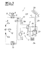
- Fig. 1 an energy system 1 with a heat pump 2 and a hot water tank 3 is shown.
- the heat pump 2 has a ventilation module 4 with which ventilation module 4 a secondary air represented by the arrows 5 and 6 can be heated or cooled.
- the heat pump 2 has according to Fig. 1 a heat exchanger 7, which is formed in the embodiment as a plate heat exchanger. With the heat exchanger 7 is a heat transfer medium can be heated, with which heat transfer medium in the hot water tank 3 recorded water is heated.
- the heat pump 2 has a coolant circuit 8, wherein in the coolant circuit 8, a compressor 9, the heat exchanger 7, designed as a four-way valve actuator 10, a condenser 11, an expansion unit 12 and an evaporator 13 are arranged.
- a coolant is compressed in the compressor 9, conveyed to the heat exchanger 7 and from the heat exchanger 7 through a first flow channel 10a of the actuator 10 to the condenser 11.
- the condenser 11 With the condenser 11, the heat stored in the coolant is discharged to the secondary air 5, whereupon the secondary air 5 leaves the ventilation module 4 as heated secondary air 6.
- the secondary air 5 is taken from a room of a building and, after the heat absorption at the condenser 11, is conveyed back into the room or into the building as heated secondary air 6 with a secondary air ventilator.
- the coolant is passed after the heat transfer to the secondary air 5 to the expansion unit 12, which expansion unit according to Fig. 1 consists of two filter driers 12a and an expansion valve 12b disposed between the filter driers 12a.
- the expanded and cooled after passing through the expansion unit 12 and coolant is passed into the evaporator 13, in which Evaporator 13, the coolant absorbs heat from an outside air or extracted from the room of the building or from the building exhaust air. From the evaporator 13, the coolant flows through a second flow channel 10b of the actuator 10 to the compressor 9, in which compressor 9, the refrigerant is re-compressed or compressed.
- Fig. 1 illustrated that the heat exchanger 7 is part of a heat transfer medium circuit 14. Apart from a possible energy or heat transfer from the coolant to a heat transfer medium flowing in the heat transfer medium circuit 14, no mass transfer between the coolant circuit 8 and the heat transfer medium circuit 14 is possible.
- the heat transfer medium circuit 14 has a designed as an efficiency pump pump 15.
- Fig. 1 is shown that the sucked from the room or from the building secondary air 5 is heated with the condenser and conveyed back as heated secondary air 6 in the room or in the building. Parallel to the heating of the secondary air 5 takes place according to Fig.
- a heating of recorded in the hot water tank 3 buffer water by the heat exchanger 7 heat from the coolant is transferred to the flowing in the heat transfer medium circuit 14 heat transfer medium.
- the heat transfer medium is buffer water.
- Fig. 1 is not shown that in the hot water tank 3, an internal heat exchanger is arranged, with which internal heat exchanger, the heat of the heat transfer medium is transferred to the stored water in the hot water tank 3.
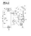
- Fig. 2 is the energy system according to Fig. 1 shown in a cooling mode.
- the compressed by the compressor 9 refrigerant flows through the heat exchanger 7 and is guided by the heat exchanger 7 through a third flow channel 10c of the adjusting device 10 to the evaporator 13.
- the coolant is according to Fig. 2 Heat to the outside air.
- the expansion unit 12 the cooled with the evaporator 13 coolant is expanded, thereby cooled and fed to the condenser 11.
- the coolant flows according to Fig.
- the energy system 1 ' according to Fig. 3 and 4 has the same coolant circuit 8 as the power system 1 according to the Fig. 1 and 2 on. Regardless of the operating mode of the coolant circuit 8 and the heat pump 2 is through the heat pump 2 according to the Fig. 3 and 4 with the heat exchanger 7, a heat transfer medium can be heated.
- the energy system 1 ' has a heat transfer medium circuit 14', in which heat transfer medium circuit 14 'is arranged with a hot water tank 3' in series switchable surface heating element 3a.
- the heat transfer medium according to the Fig. 3 and 4 is buffer water.
- a drinking water heat exchanger 22 arranged can be heated with the originating from a source, not shown, drinking water and a consumer 23 can be fed.
- the consumer 23 is in the Fig. 3 and 4 presented as a shower.
- a solar thermal heat exchanger 24 is arranged in the hot water tank 3 '.
- the solar thermal heat exchanger 24 is part of a further or separate heat transfer medium circuit 25, in which a further heat transfer medium flows from a solar thermal module 26 to the solar thermal heat exchanger 24. With the further heat transfer medium, heat recovered by the solar thermal module 26 can be transferred to the heat transfer medium, for which purpose the solar thermal heat exchanger 24 is flowed through by the further heat transfer medium after heating in the solar thermal module 26.
- the heat transfer medium according to the Fig. 3 and 4 is heated by the heat pump 2 and the heat exchanger 7.
- To ensure sufficient circulation of the heat transfer medium in the heat transfer medium circuit 14 ' has the heat transfer medium circuit 14' via a pump or pumping device 15, with which the heat transfer medium in the heat transfer medium circuit 14 'is pumped.
- Fig. 5 the connection of the provision of heated water with the ventilation of the building is shown.
- the ventilation module 4 has according to Fig. 5 via a designed as a rotary heat exchanger 16 heat exchanger through which rotary heat exchanger 16 sucked from outside the building outside air A or fresh air A is sucked. From a room 18, 19 of the building extracted exhaust Ab is according to Fig. 5 also passed through the rotary heat exchanger 16, wherein the contained in the exhaust air Ab Heat is transferred to the sucked fresh air A in the rotary heat exchanger 16.
- the heated in this way fresh air A is introduced as supply air Z in the building.
- the introduction of the supply air Z takes place in a living area 17 (drying room) of the building.
- Fig. 5 From the living area 17 is according to Fig. 5 sucked the secondary air 6 and fed to the condenser 11 of the heat pump 2, wherein in the condenser 11 takes place a temperature control of the secondary air 6, which secondary air 6 is then returned as tempered secondary air 5 in the living area 17.
- the supply air Z is mixed with the tempered secondary air 5 before being introduced into the living area 17 in the mixing container 20.
- the temperature of a room air R of the living area 17 is carried out according to Fig. 5 by a temperature of the secondary air 5, wherein preferably and according to the embodiment, the supply air Z apart from the heat transfer in the rotary heat exchanger 16 from the exhaust air Ab to the outside air A is not further heated.
- the tempered room air R is guided to a wet room 18 and a kitchen 19. From the wet room 18 and the kitchen 19, a respective exhaust air flow Ab is sucked off and fed to the rotary heat exchanger 16.
- the exhaust air flow F leaving the rotary heat exchanger 16 is in accordance with Fig. 5 over a higher energy content than the fresh air or outside air A and is according to Fig. 5 supplied to the evaporator 13 of the heat pump 2 as a heat source. In other words, the exhaust air F is supplied to the source side of the heat pump 2 after passing through the rotary heat exchanger 16. According to Fig. 5 is added to increase the flow rate at the evaporator 13 the exhaust air flow F outside air A. In Fig. 5 It is shown that the secondary air 5 is heated by the heat pump 2, so that the living area 17 is heated. Parallel to the heating of the living area 17 is according to Fig. 5 Heated water in the hot water tank 3.
Landscapes
- Engineering & Computer Science (AREA)
- Mechanical Engineering (AREA)
- General Engineering & Computer Science (AREA)
- Physics & Mathematics (AREA)
- Thermal Sciences (AREA)
- Chemical & Material Sciences (AREA)
- Combustion & Propulsion (AREA)
- Life Sciences & Earth Sciences (AREA)
- Sustainable Development (AREA)
- Heat-Pump Type And Storage Water Heaters (AREA)
Priority Applications (1)
| Application Number | Priority Date | Filing Date | Title |
|---|---|---|---|
| EP12187790.6A EP2719956A1 (fr) | 2012-10-09 | 2012-10-09 | Procédé destiné à tempérer un bâtiment et à préparer de l'eau chauffée |
Applications Claiming Priority (1)
| Application Number | Priority Date | Filing Date | Title |
|---|---|---|---|
| EP12187790.6A EP2719956A1 (fr) | 2012-10-09 | 2012-10-09 | Procédé destiné à tempérer un bâtiment et à préparer de l'eau chauffée |
Publications (1)
| Publication Number | Publication Date |
|---|---|
| EP2719956A1 true EP2719956A1 (fr) | 2014-04-16 |
Family
ID=47080267
Family Applications (1)
| Application Number | Title | Priority Date | Filing Date |
|---|---|---|---|
| EP12187790.6A Withdrawn EP2719956A1 (fr) | 2012-10-09 | 2012-10-09 | Procédé destiné à tempérer un bâtiment et à préparer de l'eau chauffée |
Country Status (1)
| Country | Link |
|---|---|
| EP (1) | EP2719956A1 (fr) |
Cited By (2)
| Publication number | Priority date | Publication date | Assignee | Title |
|---|---|---|---|---|
| CN110145906A (zh) * | 2019-05-16 | 2019-08-20 | 广东美的暖通设备有限公司 | 冷媒循环系统及其控制方法和计算机可读存储介质 |
| US20200003443A1 (en) * | 2017-02-27 | 2020-01-02 | Zinniatek Limited | A system for conditioning air in a living space |
Citations (7)
| Publication number | Priority date | Publication date | Assignee | Title |
|---|---|---|---|---|
| US4389857A (en) * | 1979-08-21 | 1983-06-28 | Genvex Energiteknik A/S | Heat exchanger |
| US4553401A (en) * | 1982-03-05 | 1985-11-19 | Fisher Ralph H | Reversible cycle heating and cooling system |
| US4598557A (en) * | 1985-09-27 | 1986-07-08 | Southern Company Services, Inc. | Integrated heat pump water heater |
| US4796437A (en) * | 1987-10-23 | 1989-01-10 | James Larry S | Multifluid heat pump system |
| US4856578A (en) * | 1988-04-26 | 1989-08-15 | Nepco, Inc. | Multi-function self-contained heat pump system |
| EP1521046A2 (fr) * | 2003-09-30 | 2005-04-06 | SANYO ELECTRIC Co., Ltd. | Circuit de fluide frigorigène et appareil de distribution d'eau chaude avec pompe à chaleur |
| DE102009052559A1 (de) * | 2009-11-10 | 2011-05-12 | Markus Kroll | Vorrichtung und Verfahren zur Wärmespeicherung und Wärmebereitstellung |
-
2012
- 2012-10-09 EP EP12187790.6A patent/EP2719956A1/fr not_active Withdrawn
Patent Citations (7)
| Publication number | Priority date | Publication date | Assignee | Title |
|---|---|---|---|---|
| US4389857A (en) * | 1979-08-21 | 1983-06-28 | Genvex Energiteknik A/S | Heat exchanger |
| US4553401A (en) * | 1982-03-05 | 1985-11-19 | Fisher Ralph H | Reversible cycle heating and cooling system |
| US4598557A (en) * | 1985-09-27 | 1986-07-08 | Southern Company Services, Inc. | Integrated heat pump water heater |
| US4796437A (en) * | 1987-10-23 | 1989-01-10 | James Larry S | Multifluid heat pump system |
| US4856578A (en) * | 1988-04-26 | 1989-08-15 | Nepco, Inc. | Multi-function self-contained heat pump system |
| EP1521046A2 (fr) * | 2003-09-30 | 2005-04-06 | SANYO ELECTRIC Co., Ltd. | Circuit de fluide frigorigène et appareil de distribution d'eau chaude avec pompe à chaleur |
| DE102009052559A1 (de) * | 2009-11-10 | 2011-05-12 | Markus Kroll | Vorrichtung und Verfahren zur Wärmespeicherung und Wärmebereitstellung |
Cited By (3)
| Publication number | Priority date | Publication date | Assignee | Title |
|---|---|---|---|---|
| US20200003443A1 (en) * | 2017-02-27 | 2020-01-02 | Zinniatek Limited | A system for conditioning air in a living space |
| US11530831B2 (en) * | 2017-02-27 | 2022-12-20 | Zinniatek Limited | System for conditioning air in a living space |
| CN110145906A (zh) * | 2019-05-16 | 2019-08-20 | 广东美的暖通设备有限公司 | 冷媒循环系统及其控制方法和计算机可读存储介质 |
Similar Documents
| Publication | Publication Date | Title |
|---|---|---|
| DE112018002250B4 (de) | Klimaanlage für Fahrzeug | |
| DE112014002644B4 (de) | Fahrzeugklimaanlagenvorrichtung | |
| EP1606564B1 (fr) | Procede et dispositif de recuperation d'energie | |
| DE112014002612B4 (de) | Fahrzeugklimaanlagenvorrichtung | |
| DE112015002160T5 (de) | Fahrzeugklimaanlage | |
| DE112016002761B4 (de) | Fahrzeugklimaanlagenvorrichtung | |
| DE112013003304T5 (de) | Fahrzeugklimaanlageneinheit | |
| DE102013112825A1 (de) | Frontmodul eines Fahrzeugs | |
| DE112013005352T5 (de) | Fahrzeugklimaanlage | |
| DE112014003888T5 (de) | Fahrzeugklimaanlage | |
| DE112013005354T5 (de) | Fahrzeugklimaanlage | |
| DE112017002005B4 (de) | Verfahren zum betrieb einer fahrzeugklimaanlage | |
| DE102006033239B4 (de) | Wärmekreissystem sowie Steuervorrichtung und Steuerverfahren dafür | |
| DE102010016077A1 (de) | Anordnung und Verfahren zur Klimatisierung eines Raums | |
| DE112014000726T5 (de) | Heizsystem | |
| DE102017212131A1 (de) | Wärmepumpenanordnung mit einem steuerbaren Wärmetauscher und Verfahren zur Herstellung einer Wärmepumpenanordnung | |
| DE102021213973A1 (de) | Thermomanagementsystem-Steuerungsverfahren für ein Fahrzeug | |
| DE10323287A1 (de) | Verfahren und Vorrichtung zur Energierückgewinnung | |
| DE19851889C2 (de) | Verfahren zum Betreiben einer Luft/Wasser-Wärmepumpe mit Energierecycling und Vorrichtung zur Durchführung des Verfahrens | |
| DE19925823C2 (de) | Vorrichtung zur Wärmerückgewinnung bei der Belüftung und Heizung von Wohn- und Nutzräumen | |
| DE202010008740U1 (de) | Klimagerät | |
| EP2719956A1 (fr) | Procédé destiné à tempérer un bâtiment et à préparer de l'eau chauffée | |
| DE112014000525T5 (de) | Heizsystem | |
| DE202012103859U1 (de) | Hausstation zur Temperierung eines Gebäudes | |
| EP0115014A2 (fr) | Procédé pour l'économie d'énergie à commande de température d'air dans des bâtiments et bâtiment permettant la mise en oeuvre du procédé |
Legal Events
| Date | Code | Title | Description |
|---|---|---|---|
| PUAI | Public reference made under article 153(3) epc to a published international application that has entered the european phase |
Free format text: ORIGINAL CODE: 0009012 |
|
| AK | Designated contracting states |
Kind code of ref document: A1 Designated state(s): AL AT BE BG CH CY CZ DE DK EE ES FI FR GB GR HR HU IE IS IT LI LT LU LV MC MK MT NL NO PL PT RO RS SE SI SK SM TR |
|
| AX | Request for extension of the european patent |
Extension state: BA ME |
|
| 17P | Request for examination filed |
Effective date: 20141014 |
|
| RBV | Designated contracting states (corrected) |
Designated state(s): AL AT BE BG CH CY CZ DE DK EE ES FI FR GB GR HR HU IE IS IT LI LT LU LV MC MK MT NL NO PL PT RO RS SE SI SK SM TR |
|
| STAA | Information on the status of an ep patent application or granted ep patent |
Free format text: STATUS: THE APPLICATION IS DEEMED TO BE WITHDRAWN |
|
| 18D | Application deemed to be withdrawn |
Effective date: 20160503 |