EP2719970A2 - Innenraumeinheit einer Klimaanlage - Google Patents
Innenraumeinheit einer Klimaanlage Download PDFInfo
- Publication number
- EP2719970A2 EP2719970A2 EP13186579.2A EP13186579A EP2719970A2 EP 2719970 A2 EP2719970 A2 EP 2719970A2 EP 13186579 A EP13186579 A EP 13186579A EP 2719970 A2 EP2719970 A2 EP 2719970A2
- Authority
- EP
- European Patent Office
- Prior art keywords
- heat exchanger
- indoor heat
- thermal insulation
- drain pan
- air
- Prior art date
- Legal status (The legal status is an assumption and is not a legal conclusion. Google has not performed a legal analysis and makes no representation as to the accuracy of the status listed.)
- Withdrawn
Links
Images


Classifications
-
- F—MECHANICAL ENGINEERING; LIGHTING; HEATING; WEAPONS; BLASTING
- F24—HEATING; RANGES; VENTILATING
- F24F—AIR-CONDITIONING; AIR-HUMIDIFICATION; VENTILATION; USE OF AIR CURRENTS FOR SCREENING
- F24F1/00—Room units for air-conditioning, e.g. separate or self-contained units or units receiving primary air from a central station
- F24F1/0007—Indoor units, e.g. fan coil units
- F24F1/0059—Indoor units, e.g. fan coil units characterised by heat exchangers
- F24F1/0063—Indoor units, e.g. fan coil units characterised by heat exchangers by the mounting or arrangement of the heat exchangers
-
- F—MECHANICAL ENGINEERING; LIGHTING; HEATING; WEAPONS; BLASTING
- F24—HEATING; RANGES; VENTILATING
- F24F—AIR-CONDITIONING; AIR-HUMIDIFICATION; VENTILATION; USE OF AIR CURRENTS FOR SCREENING
- F24F13/00—Details common to, or for air-conditioning, air-humidification, ventilation or use of air currents for screening
- F24F13/22—Means for preventing condensation or evacuating condensate
- F24F13/222—Means for preventing condensation or evacuating condensate for evacuating condensate
-
- F—MECHANICAL ENGINEERING; LIGHTING; HEATING; WEAPONS; BLASTING
- F24—HEATING; RANGES; VENTILATING
- F24F—AIR-CONDITIONING; AIR-HUMIDIFICATION; VENTILATION; USE OF AIR CURRENTS FOR SCREENING
- F24F1/00—Room units for air-conditioning, e.g. separate or self-contained units or units receiving primary air from a central station
- F24F1/0007—Indoor units, e.g. fan coil units
- F24F1/0043—Indoor units, e.g. fan coil units characterised by mounting arrangements
- F24F1/0057—Indoor units, e.g. fan coil units characterised by mounting arrangements mounted in or on a wall
-
- F—MECHANICAL ENGINEERING; LIGHTING; HEATING; WEAPONS; BLASTING
- F24—HEATING; RANGES; VENTILATING
- F24F—AIR-CONDITIONING; AIR-HUMIDIFICATION; VENTILATION; USE OF AIR CURRENTS FOR SCREENING
- F24F13/00—Details common to, or for air-conditioning, air-humidification, ventilation or use of air currents for screening
- F24F13/22—Means for preventing condensation or evacuating condensate
- F24F2013/221—Means for preventing condensation or evacuating condensate to avoid the formation of condensate, e.g. dew
Definitions
- the present invention relates to an indoor unit of an air conditioner in which drain pans each having a thermal insulation structure are provided under an indoor heat exchanger.
- an indoor unit of an air conditioner there is provided under an indoor heat exchanger with a drain pan for collecting drain water generated from dew-condensed moisture in the air on a surface of an indoor heat exchanger in cooling or humidifying operation, and for draining collected water outside the room.
- the drain pan is cooled by drain water dropping from the indoor heat exchanger, so that dew-condensation is caused on a surface of the drain pan when the surrounding air comes in contact with the surface of the drain pan, and the dew-condensed water may drop down to the room.
- the drain pan has a thermal insulation structure in which a thermal insulation member is installed.
- the insulating member is installed on an outer surface of the drain pan in some cases, and on an inner surface thereof in other cases, and other component members constituting an air outlet port and the like are often integrally formed on the outer surface of the drain pan, which makes it significantly difficult to install the insulating member on the outer surface, so that the thermal insulation member should be divided into some pieces to be installed. Furthermore, on the inner surface of the drain pan, it is necessary to insert an insulation material (cushion material) in a gap between a lower end of the indoor heat exchanger and the drain pan in order to block air flow through the gap, so as to prevent a bypass of the air flow.
- an insulation material cushion material
- Patent Literature 1 provides such a drain pan whose inner surface is provided with a thermal insulation member integrally made of a foam thermal insulation member.
- Patent Literature 1 set forth above, it is possible to reduce the number of the thermal insulation members as well as the number of man-hours for installing the thermal insulation members. Accordingly, effects such as attaining reduction in cost can be expected, but simply installing the integrally formed foam thermal insulation member on the inner surface of the drain pan cannot completely block the air flow flowing through the gap between the lower end of the indoor heat exchanger and the foam thermal insulation member, and the air flow may bypass through the gap.
- a warp in the width direction is accepted on the manufacturing basis among the indoor heat exchanger, the drain pan, the integrally formed foam thermal insulation member, and others, and there is such a problem that the bypass of the air flow cannot be prevented as far as a gap generated by the acceptable warp is shielded, or the air flow flowing through this gap is blocked.
- An object of the present invention which has been made in order to solve the problems according to the conventional art, is to provide an indoor unit of an air conditioner including a drain pan provided with a foam thermal insulation member integrally formed with an inner surface of the drain pan, capable of reducing the number of thermal insulation members and the number of man-hours for installing the thermal insulation members, as well as capable of preventing a bypass of air flow at a lower end of an indoor heat exchanger.
- An indoor unit of an air conditioner includes a unit body equipped with an indoor heat exchanger and an indoor fan therein; and at least one drain pan disposed under the indoor heat exchanger, wherein the drain pan is provided with a foam thermal insulation member integrally formed with an inner surface of the drain pan, a seat on which a lower end of the indoor heat exchanger is placed is formed on the inner surface of the foam thermal insulation member, and an air shield wall having a predetermined height for covering a front of the lower end portion of the indoor heat exchanger is uprightly disposed at a front of the seat.
- the gap generated with a warp acceptable in the manufacturing of the foam thermal insulation member and the lower end of the indoor heat exchanger can be covered by the air shield wall uprightly disposed at the front of the seat on which the lower end of the indoor heat exchanger is placed, thereby blocking the air flow flowing through this gap. Accordingly, it is possible to prevent the bypass of the air flow at the lower end portion of the indoor heat exchanger.
- thermal insulation members to be installed on the drain pan are limited to the foam thermal insulation member integrally formed with the inner surface of the drain pan, and thus it is possible to reduce the number and amount of the thermal insulation members to be used as well as the number of man-hours for installing the thermal insulation members.
- the air shield wall may be extendedly disposed along the front of the lower end portion of the indoor heat exchanger across an entire width of the lower end portion of the indoor heat exchanger.
- the air shield wall is of a sufficient height to absorb a widthways warp, tolerable in the manufacturing of the indoor heat exchanger, the drain pan, the foam thermal insulation member, as well as at least to cover a gap generated by the warp.
- the widthways warp tolerable in the manufacturing that is the warp due to tolerances in the manufacturing process, for example
- the drain pan, and the foam thermal insulation member is assumed to be 1 mm
- the height of the air shield wall is sufficiently higher than the warp, for example, 3 mm, thereby completely blocking the air flow likely to be generated through the gap due to the warp, thereby preventing air from passing.
- the seat may have a thickness dimension to accept only a part of a front half of a thickness dimension in an air flow direction of the indoor heat exchange.
- the gap generated with warp acceptable in the manufacturing of the foam thermal insulation member and the lower end of the indoor heat exchanger can be covered by the air shield wall uprightly disposed at the front of the seat on which the lower end of the indoor heat exchanger is placed, thereby blocking the air flow flowing through this gap. Accordingly, it is possible to prevent the bypass of the air flow at the lower end portion of the indoor heat exchange, and thermal insulation members to be installed on the drain pan are limited to the foam thermal insulation member integrally formed with the inner surface of the drain pan; thus it is possible to reduce the number and amount of the thermal insulation members to be used as well as the number of man-hours for installing the thermal insulation members.
- Fig. 1 shows a front view showing an indoor unit of an air conditioner according to one embodiment of the present invention with a front cover assembly of the indoor unit removed
- Fig. 2 is a perspective view thereof
- Fig. 3 is a longitudinal section view showing the vicinity of a central portion of the indoor unit
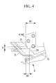
- Fig. 4 is a partial enlarged view thereof.
- the indoor unit 1 of an air conditioner includes a unit body 2 including a base 3 and a front cover assembly (not shown) detachably assembled at the front of the base 3.
- an indoor heat exchanger 4 folded or divided in an approximate A (lambda) shape extending along the front face, the upper face, and the rear face of the unit body 2; an indoor fan 5 constituted by a cross flow fan horizontally disposed downstream of the indoor heat exchanger 4; a motor (not shown) for rotationally driving the indoor fan 5; an air outlet assembly 9 with which a drain pan 6 disposed at the lower front of the indoor heat exchanger 4 is integrally formed, and in which a louver 7 and a flap 8 for adjusting air flow direction are integrally incorporated; a control box 10, and others are assembled and disposed to the base 3 in a conventional manner.
- the front cover assembly is assembled to the base 3 so as to cover the upper face, the front face, and the right and left faces of the above component members assembled to the base 3.
- This front cover assembly is provided with a suction grille for sucking room air into the unit body 2, and an air filter is disposed on the rear face of the grille, and further, a filter cleaning mechanism and the like for self-cleaning the air filter may be optionally disposed.
- the indoor heat exchanger 4 is configured to be a plate fin and tube type heat exchanger, and air shield plates 11, 12 for blocking a bypass of air flow are disposed at the folded or divided portions of the indoor heat exchanger 4.
- the plate fin and tube type heat exchanger is usually configured in such a manner that multiple plate fins 13 are installed between right and left side plates of hair pin tubes, and thereafter each hair pin tube is expanded in diameter so as to allow the tube, the fin, and the side plates to tightly contact to one another, and opening ends of every two adjacent hair pin tubes are connected to each other through a U bent pipe 14, thereby forming a serpentine piping passage; and the heat exchanger piping 15 including the U bent pipes 14 and the bent portions of the hair pin tubes outwardly projects from the right and left side plates at the end portion of the heat exchanger.
- a low pressure coolant flows through the indoor heat exchanger 4 when the indoor unit 1 equipped with the indoor heat exchanger 4 is in cooling or dehumidifying operation.
- moisture in the air becomes due-condensed on the surface of the plate fins 13, the surface of the heat exchanger piping 15 outwardly projecting from the end portion of the indoor heat exchanger 4, or the surface of others and then becomes water drops to drop down. If such water drops drop down on equipment below, and splashes to the surroundings, this may bring about various inconveniences.
- each of the drain pans 6, 17 should have a thermal insulation structure.
- the outer surface of the backside drain pan 17 has such a simple structure that a thermal insulation member 18 is installed on the outer surface of the drain pan 17 so as to obtain the thermal insulation structure.
- the drain pan 6 forwardly disposed is integrally formed with component members of an air outlet port as the air outlet assembly 9, and has such a complicated outer surface structure that it is difficult to install the thermal insulation member thereon.
- the drain pan 6 is provided with a foam thermal insulation member 19 integrally formed with its inner surface using open-cell foam of resin non-permeable to water, such as polypropylene (PP) and polystyrene (PS). Furthermore, as shown in Fig. 3 and Fig.
- a seat 20 on which the lower end portion of the indoor heat exchanger 4 (4A) is placed, and an air shield wall 21 having a predetermined height for covering the front of the lower end portion of the heat exchanger is uprightly disposed at the front of the seat 20.
- the air shield wall 21 is extendedly disposed along the front of the lower end portion of the indoor heat exchanger 4 (4A) across the entire width of this lower end portion of the indoor heat exchanger 4.
- the air shield wall 21 is configured to have such a height dimension from the upper surface of the seat 20 that is an enough height H to absorb the warp in the width direction acceptable in the manufacturing of the indoor heat exchanger 4, the drain pan 6, and the foam thermal insulation member 19, and at least to cover the gap generated with the warp.
- the warp in the width direction acceptable in the manufacturing of the indoor heat exchanger 4, the drain pan 6, and the foam thermal insulation member 19 is assumed to be 1 mm, it is sufficient to define the height H of the air shield wall 21 from the upper surface of the seat 20 to be more than 1 mm, that is, 3 mm, for example.
- the present embodiment attains the following advantageous effects.
- the indoor heat exchanger 4 in the indoor unit 1 functions as an evaporator.
- the room air circulating through the indoor fan 5 can be cooled and dehumidified, and the cooled and dehumidified air is allowed to blow into the room, thereby cooling and dehumidifying the room air.
- moisture in the air becomes dew-condensed on the surface of the plate fins 13 and others, and then becomes water drops to drop down along the surface of the plate fins 13.
- the water drops are collected in the drain pans 6, 17 respectively, and discharged outside the room through the drain hose.
- the drain pans 6, 17 have their insulation structures with the foam thermal insulation member 19 integrally formed with the inner surface of the drain pan 6, and with the thermal insulation member 18 installed on the outer surface of the drain pan 17, respectively; therefore, even if the surrounding air comes in contact with the drain pans 6, 17, there is no risk of generating dew condensation on the outer surfaces of these drain pans.
- the drain pan 6 since the drain pan 6 has such an insulation structure that the foam thermal insulation member 19 is integrally formed with the inner surface of the drain pan 6, it is unnecessary to install plural divided pieces of the thermal insulation member on the outer surface of the drain pan 6 having a complicated structure because the outer surface of the drain pan 6 is integrally formed with the component members of the air outlet port, and thermal insulation members to be installed on the drain pan 6 can be limited to the foam thermal insulation member 19 integrally formed with the inner surface of the drain pan 6. Accordingly, it is possible to reduce the number and amount of the thermal insulation members to be used as well as the number of man-hours for installing the thermal insulation members, thereby attaining reduction in cost.
- the seat 20 on which the lower end of the indoor heat exchanger 4 (4A) is placed is formed on the inner surface of the foam thermal insulation member 19, and the air shield wall 21 having the predetermined height H that covers the front of the lower end portion of the indoor heat exchanger 4 (4A) is further uprightly disposed at the front of the seat 20.
- the gap which is generated with the warp acceptable in the manufacturing of the indoor heat exchanger 4, the drain pan 6, the foam thermal insulation member 19 and others, between the foam thermal insulation member 19 and the lower end of the indoor heat exchanger 4 (4A) can be covered by the air shield wall 21 uprightly disposed at the front of the seat 20 on which the lower end of the indoor heat exchanger 4 (4A) is placed, thereby blocking the air flow flowing through this gap. Accordingly, it is possible to securely prevent the bypass of the air flow at the lower end portion of the indoor heat exchanger 4.
- the air shield wall 21 is extendedly disposed along the front of the lower end portion of the indoor heat exchanger 4 across the entire width of this lower end portion of the indoor heat exchanger 4; thus it is possible to attain the air shielding effect for the gap generated with the above warp across the entire width of this lower end portion of the indoor heat exchanger 4. Accordingly, it is possible to securely prevent the bypass of the air flow at the lower end portion of the indoor heat exchanger 4.
- the air shield wall 21 is configured to have an enough height dimension to absorb the warp in the width direction acceptable in the manufacturing of the indoor heat exchanger 4, the drain pan 6, and the foam thermal insulation member 19, and at least to cover the gap generated with the warp.
- the warp in the width direction acceptable in the manufacturing of the indoor heat exchanger 4, the drain pan 6, and the foam thermal insulation member 19 is assumed to be 1 mm
- the height H of the air shield wall 21 is sufficiently higher than the warp, that is, 3 mm, for example, thereby completely blocking the air flow flowing through the gap likely generated with the warp. Accordingly, it is possible to securely attain the air shielding effect for the gap generated with the warp, thereby preventing the bypass of the air flow.
- the seat 20 on which the lower end of the indoor heat exchanger 4 (4A) is placed is configured to have the thickness dimension W2 to accept only a part of the front half of the thickness dimension W1 in the air flow direction of the indoor heat exchanger 4.
- the present invention is not limited to the aforementioned embodiment, various modifications may be made without departing from the scope of the present invention.
- the aforementioned embodiment has been described by using an example of the drain pan 6 integrally formed with the air outlet assembly 9, but the present invention is applicable to the drain pan 6 having a standalone structure, of course.
- the present invention may also be applicable not only to the drain pan 6, but also to the backside drain pan 17 in the same manner.
- the aforementioned embodiment has been described by using an example of the indoor heat exchanger 4 folded or divided in the A shape, but the present invention may also be applicable to the indoor heat exchanger in a plane shape, of course.
- the foam thermal insulation member 19 is not limited to that in the aforementioned embodiment as far as it is made of a foam resin material which is non-permeable to water.
- the seat 20 and the air shield wall 21 may be appropriately altered in shape, dimension, and others as far as the basic functions thereof described in the aforementioned embodiment are maintained.
Landscapes
- Engineering & Computer Science (AREA)
- Chemical & Material Sciences (AREA)
- Combustion & Propulsion (AREA)
- Mechanical Engineering (AREA)
- General Engineering & Computer Science (AREA)
- Physics & Mathematics (AREA)
- Thermal Sciences (AREA)
- Devices For Blowing Cold Air, Devices For Blowing Warm Air, And Means For Preventing Water Condensation In Air Conditioning Units (AREA)
- Air Filters, Heat-Exchange Apparatuses, And Housings Of Air-Conditioning Units (AREA)
Applications Claiming Priority (1)
| Application Number | Priority Date | Filing Date | Title |
|---|---|---|---|
| JP2012225703A JP6112540B2 (ja) | 2012-10-11 | 2012-10-11 | 空気調和機の室内ユニット |
Publications (2)
| Publication Number | Publication Date |
|---|---|
| EP2719970A2 true EP2719970A2 (de) | 2014-04-16 |
| EP2719970A3 EP2719970A3 (de) | 2018-03-14 |
Family
ID=49322163
Family Applications (1)
| Application Number | Title | Priority Date | Filing Date |
|---|---|---|---|
| EP13186579.2A Withdrawn EP2719970A3 (de) | 2012-10-11 | 2013-09-30 | Innenraumeinheit einer Klimaanlage |
Country Status (2)
| Country | Link |
|---|---|
| EP (1) | EP2719970A3 (de) |
| JP (1) | JP6112540B2 (de) |
Cited By (10)
| Publication number | Priority date | Publication date | Assignee | Title |
|---|---|---|---|---|
| EP2977689A3 (de) * | 2014-07-23 | 2016-04-27 | Mitsubishi Electric Corporation | Innenraumeinheit einer klimaanlagenvorrichtung |
| AU2015205852B2 (en) * | 2014-07-31 | 2016-07-28 | Mitsubishi Heavy Industries Thermal Systems, Ltd. | Air conditioner indoor unit |
| CN106765593A (zh) * | 2017-01-18 | 2017-05-31 | 美的集团武汉制冷设备有限公司 | 空调室内机及空调器 |
| CN106765591A (zh) * | 2017-01-18 | 2017-05-31 | 美的集团武汉制冷设备有限公司 | 空调室内机及空调器 |
| CN107796103A (zh) * | 2016-08-29 | 2018-03-13 | 珠海格力电器股份有限公司 | 底壳组件及具有其的室内机 |
| WO2018133206A1 (zh) * | 2017-01-18 | 2018-07-26 | 美的集团武汉制冷设备有限公司 | 空调室内机及空调器 |
| FR3065791A1 (fr) * | 2017-05-01 | 2018-11-02 | Eric Convoi Nelson | Deflecteur d'air, recyclant, pour climatiseurs de types mural et plafonnier (unites interieures). |
| CN109084371A (zh) * | 2018-08-16 | 2018-12-25 | Tcl空调器(中山)有限公司 | 壁挂式空调器及其底座 |
| EP3705794A1 (de) * | 2019-03-08 | 2020-09-09 | Daikin Industries, Ltd. | Ausseneinheit für eine wärmepumpe |
| US20240418378A1 (en) * | 2023-06-14 | 2024-12-19 | Quilt Systems, Inc. | Indoor unit mechanical structure for improved form factor |
Families Citing this family (3)
| Publication number | Priority date | Publication date | Assignee | Title |
|---|---|---|---|---|
| JP2017062087A (ja) * | 2015-09-25 | 2017-03-30 | パナソニックIpマネジメント株式会社 | 空気調和装置 |
| CN105588205A (zh) * | 2016-01-29 | 2016-05-18 | 青岛海信日立空调系统有限公司 | 一种风管机 |
| EP3770526B1 (de) * | 2018-03-20 | 2023-09-20 | Mitsubishi Electric Corporation | Innenraumeinheit für klimaanlage |
Citations (1)
| Publication number | Priority date | Publication date | Assignee | Title |
|---|---|---|---|---|
| JP2006300431A (ja) | 2005-04-21 | 2006-11-02 | Mitsubishi Electric Corp | 空気調和機の室内機用ドレンパン、空気調和機の室内機およびその製造方法 |
Family Cites Families (10)
| Publication number | Priority date | Publication date | Assignee | Title |
|---|---|---|---|---|
| JPS5760023U (de) * | 1980-09-20 | 1982-04-09 | ||
| JPS5773514U (de) * | 1980-10-21 | 1982-05-06 | ||
| JPS6329020U (de) * | 1986-08-12 | 1988-02-25 | ||
| JPH07103503A (ja) * | 1993-10-04 | 1995-04-18 | Fujitsu General Ltd | 空気調和機の室内機 |
| JP3279490B2 (ja) * | 1996-11-20 | 2002-04-30 | 東芝キヤリア株式会社 | 天井カセット形空気調和装置 |
| US6360911B1 (en) * | 2001-03-07 | 2002-03-26 | York International Corporation | Molded drain pan |
| JP4252530B2 (ja) * | 2004-12-13 | 2009-04-08 | ダイキン工業株式会社 | 空気調和機のドレン水静菌構造 |
| CN101273236B (zh) * | 2005-10-31 | 2011-07-06 | 三菱电机株式会社 | 空调机的室内机 |
| US7418826B2 (en) * | 2006-01-20 | 2008-09-02 | Carrier Corporation | Low-sweat condensate pan |
| JP2011220558A (ja) * | 2010-04-06 | 2011-11-04 | Daikin Industries Ltd | 空気調和装置 |
-
2012
- 2012-10-11 JP JP2012225703A patent/JP6112540B2/ja active Active
-
2013
- 2013-09-30 EP EP13186579.2A patent/EP2719970A3/de not_active Withdrawn
Patent Citations (1)
| Publication number | Priority date | Publication date | Assignee | Title |
|---|---|---|---|---|
| JP2006300431A (ja) | 2005-04-21 | 2006-11-02 | Mitsubishi Electric Corp | 空気調和機の室内機用ドレンパン、空気調和機の室内機およびその製造方法 |
Cited By (16)
| Publication number | Priority date | Publication date | Assignee | Title |
|---|---|---|---|---|
| US9976758B2 (en) | 2014-07-23 | 2018-05-22 | Mitsubishi Electric Corporation | Indoor unit of air conditioning device with insulated air passage |
| EP2977689A3 (de) * | 2014-07-23 | 2016-04-27 | Mitsubishi Electric Corporation | Innenraumeinheit einer klimaanlagenvorrichtung |
| AU2015205852B2 (en) * | 2014-07-31 | 2016-07-28 | Mitsubishi Heavy Industries Thermal Systems, Ltd. | Air conditioner indoor unit |
| AU2015205852C1 (en) * | 2014-07-31 | 2016-11-24 | Mitsubishi Heavy Industries Thermal Systems, Ltd. | Air conditioner indoor unit |
| CN107796103A (zh) * | 2016-08-29 | 2018-03-13 | 珠海格力电器股份有限公司 | 底壳组件及具有其的室内机 |
| CN106765593B (zh) * | 2017-01-18 | 2019-12-06 | 美的集团武汉制冷设备有限公司 | 空调室内机及空调器 |
| CN106765593A (zh) * | 2017-01-18 | 2017-05-31 | 美的集团武汉制冷设备有限公司 | 空调室内机及空调器 |
| CN106765591A (zh) * | 2017-01-18 | 2017-05-31 | 美的集团武汉制冷设备有限公司 | 空调室内机及空调器 |
| WO2018133206A1 (zh) * | 2017-01-18 | 2018-07-26 | 美的集团武汉制冷设备有限公司 | 空调室内机及空调器 |
| CN106765591B (zh) * | 2017-01-18 | 2020-03-06 | 美的集团武汉制冷设备有限公司 | 空调室内机及空调器 |
| FR3065791A1 (fr) * | 2017-05-01 | 2018-11-02 | Eric Convoi Nelson | Deflecteur d'air, recyclant, pour climatiseurs de types mural et plafonnier (unites interieures). |
| CN109084371A (zh) * | 2018-08-16 | 2018-12-25 | Tcl空调器(中山)有限公司 | 壁挂式空调器及其底座 |
| EP3705794A1 (de) * | 2019-03-08 | 2020-09-09 | Daikin Industries, Ltd. | Ausseneinheit für eine wärmepumpe |
| WO2020184492A1 (en) * | 2019-03-08 | 2020-09-17 | Daikin Industries, Ltd. | Outdoor unit for a heat pump |
| US20240418378A1 (en) * | 2023-06-14 | 2024-12-19 | Quilt Systems, Inc. | Indoor unit mechanical structure for improved form factor |
| US12339015B2 (en) * | 2023-06-14 | 2025-06-24 | Quilt Systems, Inc. | Indoor unit mechanical structure for improved form factor |
Also Published As
| Publication number | Publication date |
|---|---|
| EP2719970A3 (de) | 2018-03-14 |
| JP2014077591A (ja) | 2014-05-01 |
| JP6112540B2 (ja) | 2017-04-12 |
Similar Documents
| Publication | Publication Date | Title |
|---|---|---|
| EP2719970A2 (de) | Innenraumeinheit einer Klimaanlage | |
| CN104110736B (zh) | 空调 | |
| US20150153095A1 (en) | Upflow condensate drain pan | |
| EP2420753A1 (de) | Klimaanlage | |
| JP6180262B2 (ja) | 空気調和装置の室内機 | |
| EP3557148B1 (de) | Klimaanlage | |
| CN100594343C (zh) | 用于蒸发器单元的凝结水排水配置 | |
| EP1813877B1 (de) | Innenraumeinheit einer Klimaanlage | |
| JP4618254B2 (ja) | 遮蔽部材および空気調和機の室内機 | |
| CN101283228B (zh) | 用于蒸发器单元的凝结水排水盘 | |
| EP2719961B1 (de) | Innenraumeinheit einer Klimaanlage | |
| EP2716991B1 (de) | Innenraumeinheit einer Klimaanlage | |
| EP3012541A2 (de) | Klimaanlagen-innenraumeinheit | |
| CN206469462U (zh) | 空调机的室内机 | |
| KR20080015944A (ko) | 증발기 유닛용 그릴 및 필터 | |
| JP4761793B2 (ja) | 排気ダクト及び該排気ダクトを備えた外部空調機 | |
| EP3184926A1 (de) | Klimaanlage | |
| JP7003256B2 (ja) | 空気調和機 | |
| JP2010121826A (ja) | 空気調和機 | |
| JP7025108B2 (ja) | 車両用空調装置 | |
| US10982878B2 (en) | Indoor unit of air-conditioning apparatus | |
| JP6847739B2 (ja) | 空気調和装置の室内機 | |
| CN118528717A (zh) | 顶置式空调 | |
| KR20150004053A (ko) | 공기조화장치 | |
| KR20070078547A (ko) | 공기조화기의 실내기 |
Legal Events
| Date | Code | Title | Description |
|---|---|---|---|
| PUAI | Public reference made under article 153(3) epc to a published international application that has entered the european phase |
Free format text: ORIGINAL CODE: 0009012 |
|
| AK | Designated contracting states |
Kind code of ref document: A2 Designated state(s): AL AT BE BG CH CY CZ DE DK EE ES FI FR GB GR HR HU IE IS IT LI LT LU LV MC MK MT NL NO PL PT RO RS SE SI SK SM TR |
|
| AX | Request for extension of the european patent |
Extension state: BA ME |
|
| RIN1 | Information on inventor provided before grant (corrected) |
Inventor name: MORI, HIRONORI Inventor name: NAITO, YASUHIRO Inventor name: HIGASHIURA, KUNIHIRO |
|
| RAP1 | Party data changed (applicant data changed or rights of an application transferred) |
Owner name: MITSUBISHI HEAVY INDUSTRIES THERMAL SYSTEMS, LTD. |
|
| PUAL | Search report despatched |
Free format text: ORIGINAL CODE: 0009013 |
|
| AK | Designated contracting states |
Kind code of ref document: A3 Designated state(s): AL AT BE BG CH CY CZ DE DK EE ES FI FR GB GR HR HU IE IS IT LI LT LU LV MC MK MT NL NO PL PT RO RS SE SI SK SM TR |
|
| AX | Request for extension of the european patent |
Extension state: BA ME |
|
| RIC1 | Information provided on ipc code assigned before grant |
Ipc: F24F 13/22 20060101AFI20180206BHEP Ipc: F24F 1/00 20110101ALI20180206BHEP |
|
| STAA | Information on the status of an ep patent application or granted ep patent |
Free format text: STATUS: REQUEST FOR EXAMINATION WAS MADE |
|
| 17P | Request for examination filed |
Effective date: 20180914 |
|
| RBV | Designated contracting states (corrected) |
Designated state(s): AL AT BE BG CH CY CZ DE DK EE ES FI FR GB GR HR HU IE IS IT LI LT LU LV MC MK MT NL NO PL PT RO RS SE SI SK SM TR |
|
| GRAP | Despatch of communication of intention to grant a patent |
Free format text: ORIGINAL CODE: EPIDOSNIGR1 |
|
| STAA | Information on the status of an ep patent application or granted ep patent |
Free format text: STATUS: GRANT OF PATENT IS INTENDED |
|
| INTG | Intention to grant announced |
Effective date: 20200514 |
|
| STAA | Information on the status of an ep patent application or granted ep patent |
Free format text: STATUS: THE APPLICATION IS DEEMED TO BE WITHDRAWN |
|
| 18D | Application deemed to be withdrawn |
Effective date: 20200925 |