EP2720127A2 - Anzeigevorrichtung und Verfahren zur Bereitstellung von Werkzeug dafür - Google Patents
Anzeigevorrichtung und Verfahren zur Bereitstellung von Werkzeug dafür Download PDFInfo
- Publication number
- EP2720127A2 EP2720127A2 EP13188178.1A EP13188178A EP2720127A2 EP 2720127 A2 EP2720127 A2 EP 2720127A2 EP 13188178 A EP13188178 A EP 13188178A EP 2720127 A2 EP2720127 A2 EP 2720127A2
- Authority
- EP
- European Patent Office
- Prior art keywords
- toolset
- tool
- display
- display device
- touch
- Prior art date
- Legal status (The legal status is an assumption and is not a legal conclusion. Google has not performed a legal analysis and makes no representation as to the accuracy of the status listed.)
- Withdrawn
Links
Images






















Classifications
-
- G—PHYSICS
- G06—COMPUTING OR CALCULATING; COUNTING
- G06F—ELECTRIC DIGITAL DATA PROCESSING
- G06F3/00—Input arrangements for transferring data to be processed into a form capable of being handled by the computer; Output arrangements for transferring data from processing unit to output unit, e.g. interface arrangements
- G06F3/01—Input arrangements or combined input and output arrangements for interaction between user and computer
- G06F3/048—Interaction techniques based on graphical user interfaces [GUI]
- G06F3/0481—Interaction techniques based on graphical user interfaces [GUI] based on specific properties of the displayed interaction object or a metaphor-based environment, e.g. interaction with desktop elements like windows or icons, or assisted by a cursor's changing behaviour or appearance
-
- G—PHYSICS
- G06—COMPUTING OR CALCULATING; COUNTING
- G06F—ELECTRIC DIGITAL DATA PROCESSING
- G06F1/00—Details not covered by groups G06F3/00 - G06F13/00 and G06F21/00
- G06F1/16—Constructional details or arrangements
- G06F1/1613—Constructional details or arrangements for portable computers
- G06F1/1615—Constructional details or arrangements for portable computers with several enclosures having relative motions, each enclosure supporting at least one I/O or computing function
- G06F1/1616—Constructional details or arrangements for portable computers with several enclosures having relative motions, each enclosure supporting at least one I/O or computing function with folding flat displays, e.g. laptop computers or notebooks having a clamshell configuration, with body parts pivoting to an open position around an axis parallel to the plane they define in closed position
- G06F1/1618—Constructional details or arrangements for portable computers with several enclosures having relative motions, each enclosure supporting at least one I/O or computing function with folding flat displays, e.g. laptop computers or notebooks having a clamshell configuration, with body parts pivoting to an open position around an axis parallel to the plane they define in closed position the display being foldable up to the back of the other housing with a single degree of freedom, e.g. by 360° rotation over the axis defined by the rear edge of the base enclosure
-
- G—PHYSICS
- G06—COMPUTING OR CALCULATING; COUNTING
- G06F—ELECTRIC DIGITAL DATA PROCESSING
- G06F1/00—Details not covered by groups G06F3/00 - G06F13/00 and G06F21/00
- G06F1/16—Constructional details or arrangements
- G06F1/1613—Constructional details or arrangements for portable computers
- G06F1/1633—Constructional details or arrangements of portable computers not specific to the type of enclosures covered by groups G06F1/1615 - G06F1/1626
- G06F1/1637—Details related to the display arrangement, including those related to the mounting of the display in the housing
- G06F1/1643—Details related to the display arrangement, including those related to the mounting of the display in the housing the display being associated to a digitizer, e.g. laptops that can be used as penpads
-
- G—PHYSICS
- G06—COMPUTING OR CALCULATING; COUNTING
- G06F—ELECTRIC DIGITAL DATA PROCESSING
- G06F1/00—Details not covered by groups G06F3/00 - G06F13/00 and G06F21/00
- G06F1/16—Constructional details or arrangements
- G06F1/1613—Constructional details or arrangements for portable computers
- G06F1/1633—Constructional details or arrangements of portable computers not specific to the type of enclosures covered by groups G06F1/1615 - G06F1/1626
- G06F1/1637—Details related to the display arrangement, including those related to the mounting of the display in the housing
- G06F1/1647—Details related to the display arrangement, including those related to the mounting of the display in the housing including at least an additional display
-
- G—PHYSICS
- G06—COMPUTING OR CALCULATING; COUNTING
- G06F—ELECTRIC DIGITAL DATA PROCESSING
- G06F3/00—Input arrangements for transferring data to be processed into a form capable of being handled by the computer; Output arrangements for transferring data from processing unit to output unit, e.g. interface arrangements
- G06F3/01—Input arrangements or combined input and output arrangements for interaction between user and computer
- G06F3/03—Arrangements for converting the position or the displacement of a member into a coded form
- G06F3/041—Digitisers, e.g. for touch screens or touch pads, characterised by the transducing means
-
- G—PHYSICS
- G06—COMPUTING OR CALCULATING; COUNTING
- G06F—ELECTRIC DIGITAL DATA PROCESSING
- G06F3/00—Input arrangements for transferring data to be processed into a form capable of being handled by the computer; Output arrangements for transferring data from processing unit to output unit, e.g. interface arrangements
- G06F3/01—Input arrangements or combined input and output arrangements for interaction between user and computer
- G06F3/048—Interaction techniques based on graphical user interfaces [GUI]
- G06F3/0481—Interaction techniques based on graphical user interfaces [GUI] based on specific properties of the displayed interaction object or a metaphor-based environment, e.g. interaction with desktop elements like windows or icons, or assisted by a cursor's changing behaviour or appearance
- G06F3/0482—Interaction with lists of selectable items, e.g. menus
-
- G—PHYSICS
- G06—COMPUTING OR CALCULATING; COUNTING
- G06F—ELECTRIC DIGITAL DATA PROCESSING
- G06F3/00—Input arrangements for transferring data to be processed into a form capable of being handled by the computer; Output arrangements for transferring data from processing unit to output unit, e.g. interface arrangements
- G06F3/01—Input arrangements or combined input and output arrangements for interaction between user and computer
- G06F3/048—Interaction techniques based on graphical user interfaces [GUI]
- G06F3/0484—Interaction techniques based on graphical user interfaces [GUI] for the control of specific functions or operations, e.g. selecting or manipulating an object, an image or a displayed text element, setting a parameter value or selecting a range
-
- G—PHYSICS
- G06—COMPUTING OR CALCULATING; COUNTING
- G06F—ELECTRIC DIGITAL DATA PROCESSING
- G06F3/00—Input arrangements for transferring data to be processed into a form capable of being handled by the computer; Output arrangements for transferring data from processing unit to output unit, e.g. interface arrangements
- G06F3/01—Input arrangements or combined input and output arrangements for interaction between user and computer
- G06F3/048—Interaction techniques based on graphical user interfaces [GUI]
- G06F3/0487—Interaction techniques based on graphical user interfaces [GUI] using specific features provided by the input device, e.g. functions controlled by the rotation of a mouse with dual sensing arrangements, or of the nature of the input device, e.g. tap gestures based on pressure sensed by a digitiser
- G06F3/0488—Interaction techniques based on graphical user interfaces [GUI] using specific features provided by the input device, e.g. functions controlled by the rotation of a mouse with dual sensing arrangements, or of the nature of the input device, e.g. tap gestures based on pressure sensed by a digitiser using a touch-screen or digitiser, e.g. input of commands through traced gestures
- G06F3/04883—Interaction techniques based on graphical user interfaces [GUI] using specific features provided by the input device, e.g. functions controlled by the rotation of a mouse with dual sensing arrangements, or of the nature of the input device, e.g. tap gestures based on pressure sensed by a digitiser using a touch-screen or digitiser, e.g. input of commands through traced gestures for inputting data by handwriting, e.g. gesture or text
-
- G—PHYSICS
- G06—COMPUTING OR CALCULATING; COUNTING
- G06F—ELECTRIC DIGITAL DATA PROCESSING
- G06F3/00—Input arrangements for transferring data to be processed into a form capable of being handled by the computer; Output arrangements for transferring data from processing unit to output unit, e.g. interface arrangements
- G06F3/14—Digital output to display device ; Cooperation and interconnection of the display device with other functional units
-
- G—PHYSICS
- G06—COMPUTING OR CALCULATING; COUNTING
- G06F—ELECTRIC DIGITAL DATA PROCESSING
- G06F2203/00—Indexing scheme relating to G06F3/00 - G06F3/048
- G06F2203/048—Indexing scheme relating to G06F3/048
- G06F2203/04804—Transparency, e.g. transparent or translucent windows
-
- G—PHYSICS
- G06—COMPUTING OR CALCULATING; COUNTING
- G06F—ELECTRIC DIGITAL DATA PROCESSING
- G06F2203/00—Indexing scheme relating to G06F3/00 - G06F3/048
- G06F2203/048—Indexing scheme relating to G06F3/048
- G06F2203/04807—Pen manipulated menu
-
- G—PHYSICS
- G06—COMPUTING OR CALCULATING; COUNTING
- G06F—ELECTRIC DIGITAL DATA PROCESSING
- G06F2203/00—Indexing scheme relating to G06F3/00 - G06F3/048
- G06F2203/048—Indexing scheme relating to G06F3/048
- G06F2203/04808—Several contacts: gestures triggering a specific function, e.g. scrolling, zooming, right-click, when the user establishes several contacts with the surface simultaneously; e.g. using several fingers or a combination of fingers and pen
Definitions
- the present invention relates to a display device and a method of providing a tool therefor, and more particularly, to a display device to display a task screen through a multi-display and to provide a tool usable on the task screen, and a method of providing a tool therefor.
- GUIs graphical user interfaces
- the GUI may be provided in an optimized form so that the user can intuitively know an operation of a running application and can control a corresponding device more easily and swiftly.
- the portable devices are able to display a plurality of task screens displaying a single application or a plurality of applications.
- the plurality of task screens may be provided through one or more touch screens that are split physically or graphically.
- the present invention provides a multi display device and a method of providing various toolsets, which allow a user to control an application intuitively and easily.
- a multi display device including a first body including a first display, a second body including a second display, a hinge to connect the first and second bodies, and, a controller to display a toolset comprising tools corresponding to an operation state of the multi display device on a screen of at least one of the first and second displays when a user manipulation to display a toolset is input, and to perform an operation corresponding to the selected tool when one tool is selected from the toolset, wherein a display position of a tool displayed on the toolset is variable.
- the toolset may include a tool that is usable in an application that is being executed in the multi display device.
- the toolset may include a dedicated tool that is used only for the application, and a common tool that is commonly usable in a plurality of applications, and the controller may place the dedicated tool in the toolset in preference to the common tool.
- the controller may display a tool icon corresponding to the selected tool, and may perform an operation corresponding to the tool while changing a display position of the tool icon according to user manipulation.
- the controller may display a first lower level toolset listing the first lower level tool on one side of the toolset, and, when one first lower level tool is selected from the first lower level toolset and there is a second lower level tool belonging to the selected first lower level tool, the controller may display a second lower level toolset listing the second lower level tool on one side of the first lower level toolset.
- a size and a shape of the toolset may be adjusted differently according to a number of tools that are usable in the application.
- the user manipulation may be a touch gesture
- the toolset may be a graphic UI in which tools are arranged in a semi-circular form with reference to a point where the touch gesture ends.
- the first lower level toolset may be a graphic UI of a circular bar shape or a graphic UI of a button shape that is displayed along an outer edge of the toolset.
- the controller may newly display a hidden tool on the toolset according to user manipulation.
- the user manipulation may be a touch and drag gesture that is made from a border region of the first body in a first direction toward the first display or from a border region of the second body in a second direction toward the second display, and the controller may display the toolset on the first display or the second display according to a direction in which the touch and drag gesture is made.
- the user manipulation may be a touch and drag gesture that is made from a connection region between the first body and the second body in a first direction toward the first display or in a second direction toward the second display, and the controller may display the toolset on the first display or the second display according to a direction in which the touch and drag gesture is made.
- the toolset may further include at least one icon to select an application that is executable in the multi display device, and, when the icon is selected from the toolset, the controller may execute an application corresponding to the selected icon on a certain region of the first display or the second display.
- the toolset may enable tool update and tool addition.
- the controller may provide a tool region on at least one of the first display and the second display, and may move a tool that is selected by the user from among tools of the toolset to the tool region and may display the tool on the tool region.
- the user manipulation may be a touch that is performed by an external object on the first display or the second display, and, when the touch is performed, the controller may display the toolset including a tool corresponding to a kind of the external object on a touch point, and may assign a function of a tool selected from the toolset to the external object.
- the controller may display a pattering instrument image and a writing instrument image on touch points, and, when the touch point of the second external object is moved, the controller may display the patterning instrument image and a line that is drawn according to a moving path of the second external object.
- the multi display device may further include a communicator that receives a control signal from a stylus pen to manipulate the multi display device, and, when a control signal to display the toolset is input from the stylus pen, the controller may determine that the user manipulation is performed.
- the toolset may include at least one of an internet browser adjustment menu, a music player adjustment menu, a moving image player adjustment menu, a camera option adjustment menu, a message adjustment menu, a memo adjustment menu, a gallery adjustment menu, an e-book adjustment menu, a contact information adjustment menu, a calendar adjustment menu, a writing characteristic adjustment menu, and an e-book adjustment menu.
- a method of providing a tool of a multi display device that includes a first body including a first display, and a second body including a second display, the method including when user manipulation to display a toolset is input, displaying a toolset including tools corresponding to an operation state of the multi display device on a screen of at least one of the first display and the second display, and when one tool is selected from the toolset, performing an operation corresponding to the selected tool, wherein a display position of a tool displayed on the toolset is variable.
- the toolset may include a tool that is usable in an application that is being executed in the multi display device.
- the toolset may include a dedicated tool that is used only for the application, and a common tool that is commonly usable in a plurality of applications, and the displaying the toolset may include placing the dedicated tool in the toolset in preference to the common tool.
- the performing the operation corresponding to the selected tool may include, when a tool that is usable in the application that is being executed is selected from the toolset, displaying a tool icon corresponding to the selected tool, and performing an operation corresponding to the tool while changing a display position of the tool icon according to user manipulation.
- the performing the operation corresponding to the selected tool may include, when there is a first lower level tool belonging to the selected tool, displaying a first lower level toolset listing the first lower level tool on one side of the toolset, and, when one first lower level tool is selected from the first lower level toolset and there is a second lower level tool belonging to the selected first lower level tool, displaying a second lower level toolset listing the second lower level tool on one side of the first lower level toolset.
- a size and a shape of the toolset may be adjusted differently according to a number of tools that are usable in the application.
- the user manipulation may be a touch gesture
- the toolset may be a graphic UI in which tools are arranged in a semi-circular form with reference to a point where the touch gesture ends.
- the first lower level toolset may be a graphic UI of a circular bar shape or a graphic UI of a button shape that is displayed along an outer edge of the toolset.
- the method may further include newly displaying a hidden tool on the toolset according to user manipulation.
- the user manipulation may be a touch and drag gesture that is made from a border region of the first body in a first direction toward the first display or from a border region of the second body in a second direction toward the second display, and the displaying on the screen may include displaying the toolset on the first display or the second display according to a direction in which the touch and drag gesture is made.
- the user manipulation may be a touch and drag gesture that is made from a connection region between the first body and the second body in a first direction toward the first display or in a second direction toward the second display, and the displaying on the screen may include displaying the toolset on the first display or the second display according to a direction in which the touch and drag gesture is made.
- the toolset may further include at least one icon to select an application that is executable in the multi display device, and the performing the operation corresponding to the selected tool may include, when the icon is selected from the toolset, executing an application corresponding to the selected icon on a certain region of the first display or the second display.
- the toolset may enable tool update and tool addition.
- the method may further include providing a tool region on at least one of the first display and the second display, and moving a tool that is selected by the user from among tools of the toolset to the tool region and displaying the tool on the tool region.
- the user manipulation may be a touch that is performed by an external object on the first display or the second display, and the displaying on the screen may include, when the touch is performed, displaying the toolset including a tool corresponding to a kind of the external object on a touch point.
- the performing the operation corresponding to the tool may include assigning a function of a tool selected from the toolset to the external object.
- the method may further include, when a patterning instrument is assigned to a first external object and a writing instrument is assigned to a second external object, and, when a touch is performed by the first external object and the second external object on the screen of the first or second display, displaying a pattering instrument image and a writing instrument image on touch points, and, when the touch point of the second external object is moved, displaying the patterning instrument image and a line that is drawn according to a moving path of the second external object.
- the method may further include receiving a control signal from a stylus pen to manipulate the multi display device, and when a control signal to display the toolset is input from the stylus pen, determining that the pre-defined user manipulation is performed.
- the toolset may include at least one of an internet browser adjustment menu, a music player adjustment menu, a moving image player adjustment menu, a camera option adjustment menu, a message adjustment menu, a memo adjustment menu, a gallery adjustment menu, an e-book adjustment menu, a contact information adjustment menu, a calendar adjustment menu, a writing characteristic adjustment menu, and an e-book adjustment menu.
- a non-transitory computer readable recording medium having embodied thereon a computer program to execute a method of providing a tool of a multi display device, which includes a first display and a second display, the method including when user manipulation to display a toolset is input, displaying a toolset including tools corresponding to an operation state of the multi display device on a screen of at least one of the first display and the second display, and when one tool is selected from the toolset, performing an operation corresponding to the selected tool.
- a multi display device including a first body comprising a first display, a second body comprising a second display, a hinge to connect the first and second bodies, a communicator to communicate with an external device that provides an input to manipulate at least one of the first display and the second display, and a controller to differentiate between the input of the external device and another input of a user to display at least one toolset on at least one of the first display and the second display based on the differentiation to perform the manipulation.
- the multi display device may further include at least one sensor to sense a location with respect to at least one of the first display and the second display of the input of the external device and the another input of a user.
- the at least one toolset may be displayed on the at least one of the first display and the second display according to an operation state of the multi display device in response to the sensing.
- the at least one toolset may include at least one tool displayed thereon to allow the user to perform the manipulation.
- a display position of the at least one tool displayed on the at least one toolset may be variable.
- the at least one toolset may appear when a tool corresponding to an already displayed toolset is selected.
- a location of the at least one toolset on the at least one of the first display and the second display may be variable based on at least one of the input of the external device and another input of the user.
- a first tool of the at least one toolset may be selected with respect to the input of the external device and a second tool of the at least one toolset may be selected with respect to the another input of the user to perform the manipulation.
- the first tool and the second tool may be operated simultaneously.
- the external device may include a stylus pen, including a sensor to sense movement of the stylus pen with respect to the first body and the second body, and a communicator to send results of the sensed movement to the communicator of the multi display device.
- the stylus pen may perform the manipulation based on the movement.
- a multi display device refers to a device that includes a plurality of displays including one or more touch screens, and is configured to execute an application or display a content.
- the multi display device may be implemented by a tablet personal computer (PC), a notebook computer, a laptop computer, a portable multimedia player (PMP), a personal digital assistant (PDA), a smart phone, a mobile phone, and a digital album, but is not limited thereto.
- PC personal computer
- PMP portable multimedia player
- PDA personal digital assistant
- smart phone a mobile phone
- digital album digital album
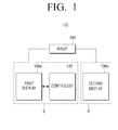
- a multi display device 100 includes a first body 2, a second body 4, and a hinge 185.
- the first body 2 is a single independent exterior component including a controller 130 and a first display 190a
- the second body 4 is another independent exterior component including a second display 190b.
- the controller 130 is provided in the first body 2 in FIG. 1 , the controller 130 may be included in the second body 4 or a plurality of controllers 130 may be provided in the first and second bodies 2 and 4, respectively.
- the first and second bodies 2 and 4 may further include various circuits, chips or signal lines in addition to the above-described elements, but an illustration of a detailed configuration is omitted for convenience of explanation.
- the first body 2 and the second body 4 are connected to each other by means of the hinge 185.
- the hinge 185 supports the first body 2 and the second body 4 to allow the first body 2 and the second body 4 to rotate with respect to the hinge 185. Rotation angles of the first body 2 and the second body 4 may be determined variously according to the shape of the hinge 185.
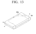
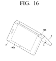
- the first and second displays 190a and 190b may be closed to be brought into contact with each other, or may be bent back in the opposite direction and opened to have their rear surfaces brought into contact with each other. Also, the first and second displays 190a and 190b may be opened to be unfolded 180 degrees according to a configuration of the hinge 185.
- the first body 2 and the second body 4 may be folded or unfolded with reference to the hinge 185 according to exemplary embodiments of the present invention will be explained in detail below.
- the first and second displays 190a and 190b may display a multimedia content playback screen, an application execution screen, a desktop screen including an icon, and a web browsing screen under the control of the controller 130.
- the first and second displays 190a and 190b, respectively, may be implemented by using a touch screen. Accordingly, when a part of a user's body (for example, the user's fingers or thumb) or an inputting means (for example, a stylus pen), which can be sensed, touches the first and second displays 190a and 190b, respectively, the controller 130 may perform various operations according to coordinate values of the touch point and a shape of the touch gesture.
- the touch gesture includes various gestures such as simple touch, approach, touch and drag, double touch, a flick, and a rubbing.
- the user may control the operations of the multi display device using the touch gesture.
- the multi display device is equipped with a micro phone, a camera, or a button
- the user may control the operations of the multi display device using various combinations of different user manipulations such as voice manipulation to input a voice command through the microphone, motion manipulation to input a motion gesture using the camera, and button manipulation to perform various selection operations.
- Various shapes and motions of such user manipulations and corresponding control operations may be set in advance by a manufacturer of the multi display device or the user.
- the controller 130 performs an operation corresponding to the user manipulation using the first display 190a and the second display 190b.
- the controller 130 may display a toolset corresponding to an operation state of the multi display device on at least one of the first display 190a and the second display 190b.
- the toolset may display identifiers of various tools, such as icons and names.
- the tool recited herein refers to various functions that the user can use in relation to a currently performed operation.
- various tools such as font adjustment, thickness adjustment, pen, eraser, and ruler may be used, but are not limited thereto.
- the controller 130 displays a toolset including the above-described tools on a screen of at least one of the first and second displays 190a and 190b, respectively.
- a toolset including a tool to add an icon to the home screen, a tool to execute a widget, and a tool to change a desktop image may be displayed.
- the toolset may include different tools according to a current operation state of the multi display device.
- the user may select at least one tool from the toolset.
- the controller 130 performs an operation corresponding to the selected tool.
- a line may be drawn by the pen along a trajectory of a user's finger touching and moving along at least one of the first and second displays 190a and 190b, respectively.
- Such a toolset may display the tools of the toolset variably according to user's manipulation. Specifically, display positions of the tools included in the toolset and display or non-display of the tools are not always fixed, and may be adjusted according to user's manipulation. For example, a position of a tool of the toolset may be changed according to user's manipulation.
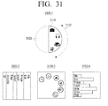
- a tool that is placed on a variable region of the toolset that is not displayed on the screen may be displayed on a display region of the tool set that is displayed on the screen of the display by a user's touch (for example, a drag gesture such as rotating a dial). This will be explained in detail below with reference to FIG. 31 .
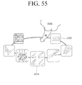
- the toolset is not necessarily fixed and may be changed by updating the toolset by installing new software via a disc, memory, or the Internet, and tools may also be added or deleted. Also, the icons or names identifying the tools may be changed. Updating the tool will be explained below with reference to FIG. 55 .
- the toolset may include a tool that is usable in an application that is being executed in the multi display device 100.
- the toolset may include a dedicated tool and a common tool.
- the dedicated tool is a tool that is usable only in an application that is being currently executed in the multi display device.
- the common tool is a tool that is commonly usable not only in the application that is being currently executed but also in a plurality of applications.
- the controller 130 may display the dedicated tool on the toolset in preference to the common tool.
- the dedicated tool when a camera application is being executed, the dedicated tool may be a tool that is used only in the camera application, such as a flash setting tool, a front and rear camera conversion tool, a moving image shooting conversion tool, a focus mode setting tool, and a timer setting tool, but is not limited thereto.
- the common tool is a tool that is executable regardless of the camera application such as a message sending tool, a device environment setting tool, and a calling tool, but is not limited thereto.
- the multi display device 100 displays the dedicated tool of the running application in preference to the common tool, thereby allowing the user to easily use the tool of the running application.
- the tools may be divided into an upper level tool and a lower level tool according to their respective characteristics.
- the lower level tool refers to a sub tool that belongs to the upper level tool.
- specific writing instruments such as a pencil, a pen, a brush, and a crayon may be lower level tools.
- the tools that are included in the initially displayed toolset may refer to upper level tools.
- the controller 130 may display a first lower level toolset listing the first lower level tool on one side of the toolset.
- a second lower level toolset listing the second lower level tool may be displayed on one side of the first lower level toolset.
- the writing instrument tool is an uppermost level tool and tools such as a pencil, a pen, a brush, and a crayon are first lower level tools belonging to the tool instrument tool
- various pens of different thicknesses may be provided as second lower level tools for the pen.
- the toolset may have its size and shape adjusted according to a number of tools usable in the running application.
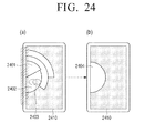
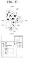
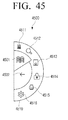
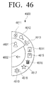
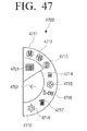
- the toolset may be a graphic user interface (UI) in which tools are arranged in a semi-circular form with reference to a point where a touch gesture ends
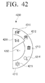
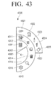
- the lower level toolset may be a graphic UI of a circular bar shape or a graphic UI of a button shape that is displayed along an outer edge of the upper level toolset.
- at least one of the toolset and the lower level toolset may display hidden tools that are newly displayed according to user manipulation.
- the hidden tool refers to a tool that is placed on the variable region of the toolset that is not displayed on the display. It is common that frequently used tools may be placed on the display region of the toolset and the other tools may be placed on the variable region.
- the hidden tool that is placed on the variable region of the toolset may be installed by updating the toolset. The hidden tool will be explained in detail below with reference to FIG. 31 .
- the toolset UI has a semi-circular shape in the above example, this should not be considered as limiting and the toolset UI may be implemented in the form of a water drop UI, a card pocket UI, a quadrangular menu bar UI, or a quadrangular graph UI.
- the toolset UI will be explained in detail below with reference to FIGS. 31 through 33 .
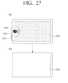
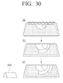
- the user manipulation according to an exemplary embodiment of the present invention may be a touch and drag gesture that allows a user to touch a connection region between the first body 2 and the second body 4 and perform a drag in a first direction toward the first display 190a or in a second direction toward the second display 190b.
- the user manipulation may be a touch and drag gesture that allows a user to touch a border region of the first body 2 and perform a drag in a first direction toward the first display 190a, or touch a border region of the second body 4 and perform a drag in a second direction toward the second display 190b.
- the controller 130 may display the toolset on the first display 190a or the second display 190b according to a direction or a location in which the touch and drag gesture is performed.
- the toolset may further include at least one icon to select an application that is executable in the multi display device 100.
- the controller 130 may execute an application corresponding to the selected icon on a certain region of the first display 190a or the second display 190b.
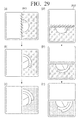
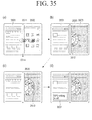
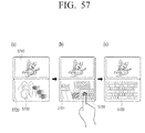
- the controller 130 may provide a tool region on at least one of the first display 190a and the second display 190b, and may move a tool that is selected from among the tools displayed on the toolset to the tool region and display it.
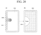
- the controller 130 may display a toolset including tools corresponding to a type of the external object on a touch point, and may assign a function of a tool selected from the toolset to the external object.
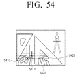
- the controller 130 displays a patterning instrument image and a writing instrument image on the touch point, and, when the touch point of the second external object is moved, the controller 130 may display the patterning instrument image and a line that is drawn along a moving path of the second external object.
- the patterning instrument may include various straight ruler, squares ruler, wave-from ruler, protractors, and circular plates
- the writing instrument may include pencils, pens, brushes, and crayons displaying various colors.
- the multi display device 100 is able to differentiate between the first and second external objects.
- the controller 130 may determine that user manipulation is performed.
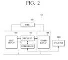
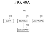
- FIG. 2 is a schematic block diagram illustrating configurations of a multi display device 100 and a stylus pen 4800 according to an exemplary embodiment of the present invention.
- the multi display device 100 may include first and second displays 190a and 190b, respectively, a hinge 185, a controller 130, and a communicator 110, and may receive external input from the stylus pen 4800.
- first and second displays 190a and 190b, respectively, the hinge 185, and the controller 130 have been described above with reference to FIG. 1 , and thus a redundant explanation is omitted.
- the communicator 110 receives a control signal to manipulate the multi display device 100 from the stylus pen 4800.
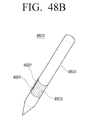
- the stylus pen 4800 is of a pencil type and refers to an auxiliary device to manipulate the multi display device.
- the stylus pen 4800 may transmit a control signal to display a toolset to the communicator 110 of the multi display device 100.
- a general function of the stylus pen 4800 will be explained in detail with reference to FIG. 48 .
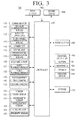
- FIG. 3 is a block diagram illustrating a configuration of a multi display device in detail according to an exemplary embodiment of the present invention.
- the multi display device 100 includes a communicator 110, a multimedia part 120, a controller 130, a photographer 140, a sensor 150, an inputter/outputter 160, a storage 170, a power supply 180, and first and second displays 190a and 190b, respectively.
- the communicator 110 may be configured to exchange information with an external device using various wired/wireless communication methods.
- the external device recited herein may include at least one of another device, a mobile phone, a smart phone, a tablet PC, a computer server, and a digital TV. These devices may be connected to the multi display device 100 through a communication network.
- the communicator 110 may include wireless communication modules such as a cellular communication module 112, a wireless LAN module 112, a short-range communication module 113, a GPS communication module 115, a broadcast communication module 116, and a connector 114 including at least one of wire communication modules such as a high-definition multimedia interface (HDMI), a universal serial bus (USB), and an institute of electrical and electronics engineers (IEEE) 1394, but is not limited thereto.
- wireless communication modules such as a cellular communication module 112, a wireless LAN module 112, a short-range communication module 113, a GPS communication module 115, a broadcast communication module 116, and a connector 114 including at least one of wire communication modules such as a high-definition multimedia interface (HDMI), a universal serial bus (USB), and an institute of electrical and electronics engineers (IEEE) 1394, but is not limited thereto.
- HDMI high-definition multimedia interface
- USB universal serial bus
- IEEE institute of electrical and electronics engineers
- the cellular communication module 111 uses wireless access technology according to a cellular communication protocol under the control of the controller 130, and allows the multi display device 100 to be connected with an external device (in particular, a base station of a cellular system) through at least one antenna or a plurality of antennas (not illustrated).
- an external device in particular, a base station of a cellular system
- antennas not illustrated
- the cellular communication module 111 exchanges radio signals containing a voice, a video, a short message service (SMS) message, or a multimedia messaging service (MMS) message with another device that is accessible such as a mobile phone having a phone number input to the multi display device 100, a smart phone, and a tablet PC.
- SMS short message service
- MMS multimedia messaging service
- the wireless LAN module 112 accesses a wireless access point (AP) (not illustrated) that exists within a predetermined range under the control of the controller 130, and is connected to the Internet.
- the wireless LAN module 112 may support the wireless LAN standard of IEEE, but is not limited thereto.
- the short-range communication module 113 is configured to allow the multi display device 100 to perform short-range communication with an external device under the control of the controller 130.
- the short-range communication module 113 may include at least one of a Bluetooth module, an infrared data association (IrDA) module associated with an IrDA data 1.4 standard, a near field communication (NFC) module, a Wi-Fi module, and a Zigbee module, but is not limited thereto.
- the Bluetooth module transmits a data stream in the form of a data packet using 2402 ⁇ 2480 MHz, except for 2MHz after 2400MHz and 3.5M.Hz before 2483.5MHz of industrial scientific and medical (ISM), that is, 79 channels in total.
- ISM industrial scientific and medical
- the IrDA module transmits data using infrared rays.
- the infrared rays have a longer wavelength than that of visible rays and thus smoothly pass through minute particles drifting in the air.
- the infrared rays can easily guarantee a wide bandwidth in comparison with electromagnetic wave and has the merit of transmitting data at high speed.
- the multi display device 100 is able to wirelessly communicate with an external device at a rate of up to 16Mbps within a 1M distance.
- the NFC module communicates with an external device in a non-contact short-range wireless communication method using a frequency band of 13.56Mz.
- the external device may include a module including an NFC tag and the multi display device 100 may include an NFC reader.
- the external device and the multi display device 100 may include an NFC tag and an NFC reader, respectively.
- the Wi-Fi module performs short-range communication according to the IEEE 802.11 standard. According to the IEEE 802.11n, data can be transmitted at a rate of up to 150Mbps. If multiple-input and multiple-out (MIMO) technology to increase output using a plurality of antennas is applied, data can be transmitted at a rate of up to 600Mbps. In particular, the Wi-Fi direct method guarantees the above rate and also enables direct communication between devices without a separate AP.
- MIMO multiple-input and multiple-out
- the communicator 110 may include the Zigbee module.
- the Zigbee is a short-range communication method according to IEEE 802.15.4 technology standard, and has a transfer rate of 250Kbps, 20Kbps, and 40 Kbps. This method is suitable for relatively simple data transfer.
- the communicator 110 may be implemented in the above-described various short-range communication methods, but is not limited thereto.
- the connector 114 is configured to provide an interface with various devices such as a USB 2.0, a USB 3.0, an HDMI, and IEEE 1394, but is not limited thereto.
- the connector 114 may be used as an interface to connect the multi display device 100 and an external device or a power source.
- the connector 114 may transmit data stored in the storage 170 of the multi display device 100 to the external devices or receive data from the external device through a cable connected to the connector 114 under the control of the controller 130.
- Power may be input from the power source through the cable connected to the connector 114, or a battery (not illustrated) may be charged through the cable.
- the GPS module 115 receives electromagnetic waves from a plurality of GPS satellites (not illustrated) orbiting around the earth, and calculates a location of the multi display device 100 using a time of arrival from the GPS satellites (not illustrated) to the multi display device 100 and GPS parameters.
- the broadcasting communication module 116 may receive broadcast signals (for example, TV broadcast signals, radio broadcast signals, or data broadcast signals) and additional broadcast information (for example, electronic program guide (EPG) or electronic service guide (ESG)) from a broadcasting station through a broadcast communication antenna (not illustrated) under the control of the controller 130.
- broadcast signals for example, TV broadcast signals, radio broadcast signals, or data broadcast signals
- additional broadcast information for example, electronic program guide (EPG) or electronic service guide (ESG)
- EPG electronic program guide
- ESG electronic service guide
- the multimedia part 120 is included to reproduce moving image contents, audio contents, and other various multimedia contents.
- the multimedia part 120 processes the multimedia content using a parser or a codec and reproduces the content.
- the multimedia part 120 includes an audio reproducing module 121 and a video reproducing module 122.
- the audio reproducing module 121 may reproduce a stored or received digital audio file (for example, a file having an extension of mp3, wma, ogg, or wav) under the control of the controller 130.
- a stored or received digital audio file for example, a file having an extension of mp3, wma, ogg, or wav
- the video reproducing module 122 may reproduce a stored or received digital moving image file (for example, a file having an extension of mpeg, mpg, mp4, avi, mov, or mkv) under the control of the controller 130.
- a stored or received digital moving image file for example, a file having an extension of mpeg, mpg, mp4, avi, mov, or mkv
- the video reproducing module 122 supports various codecs to be able to reproduce a digital video file. That is, the video reproducing module 122 decodes video data using a codec corresponding to an encoding method of the video file to be reproduced.
- the controller 130 controls the communicator 110, the multimedia part 120, the photographer 140, the sensor 150, the inputter/outputter 160, the storage 170, the power supply 180, and the first and second displays 190a and 190b, respectively.
- the controller 130 provides a clock to hardware, and includes a CPU to transmit control signals, a memory to temporarily or semi-permanently store a process, a GPU to process graphics, and a system bus to transmit data between the memory and the CPU and the GPU.
- the controller 130 includes an operating system (OS) to run the hardware configuration, and an application to provide a user interface on the OS and transmit the interface to a framework.
- OS operating system
- the photographer 140 may include at least one of a first camera 141 and a second camera 142 as illustrated in FIG. 3 . Although only the first camera 141 and the second camera 142 are illustrated in FIG. 3 , an additional camera may be included according to an exemplary embodiment of the present invention.
- Each of the first and second cameras 141 and 142 includes a shutter (not illustrated), a lens 5110 of FIG. 23 , an aperture (not illustrated), and a charge coupled device (CCD) image sensor (not illustrated), and an analogue/digital converter (ADC).
- the shutter is a mechanism to adjust an amount of exposed light along with the aperture.
- the lens receives light from an external light source and processes an image.
- the aperture adjusts an amount of incident light according to how much it is opened or closed.
- the CCD image sensor accumulates light input through the lens and outputs the image photographed by the lens in synchronization with a vertical sync signal according to an amount of accumulated light. An image is obtained by the CCD image sensor that converts light reflected from a subject into an electric signal.
- a filter such as a color filter array (CFA) may be employed.
- CFA allows each pixel to pass only the light representing one color, and has a regularly arranged configuration and has various forms according to its arrangement configuration.
- the ADC converts an analogue image signal output from the CCD image sensor into a digital signal.
- CMOS complementary metal oxide semiconductor
- the first camera 141 and the second camera 142 may be provided in a housing of the multi display device 100 or may be connected to the multi display device 100 using a separate connecting means. At least one of the first camera 141 and the second camera 142 may include an auxiliary light source (for example, a flash (not illustrated)) to provide necessary light to perform photographing.
- an auxiliary light source for example, a flash (not illustrated)
- the first camera 141 may be disposed on a front surface of the multi display device 100, and the second camera 142 may be disposed on a rear surface of the multi display device 100.
- the first camera 141 and the second camera 142 may be adjacent to each other (for example, a gap between the first camera 141 and the second camera 142 is larger than 1cm and less than 8cm) to photograph a 3D still image or a 3D moving image.
- the first camera 141 may be displayed on a first panel and the second camera 141 may be disposed on a second panel.
- the photographer 140 may detect a user's motion or shape through at least one of the first camera 141 and the second camera 142, and may transmit the user's motion or shape to the controller 130 as an input to execute or control an application.
- the user's motion may refer to a user's hand motion sensed by the first or second camera.
- the user's shape may refer to a facial shape of the user sensed by the first or second camera.
- the multi display device 100 may detect a user's motion using other means such as an infrared ray sensor, and may execute or control an application in response to the motion.
- the sensor 150 is to sense various state changes such as a user's touch on the multi display device 100, a user motion, and a motion of the multi display device 100.
- the touch sensor or proximity sensor has been described as an example of the sensor 150.
- the sensor 150 may include at least one of a touch sensor 151, a geomagnetic sensor 152, an acceleration sensor 153, a hinge sensor 154, and a proximity sensor 155.
- the touch sensor 151 is a sensor that can sense a touch of a user object on the display of the multi display device 100. That is, the touch sensor 151 senses input to select an object displayed on a display screen by touching the first or second display 190a or 190b using a body such as a finger or a inputting means which can be sensed.
- the touch sensor 151 may be divided into a capacitive touch sensor and a piezoelectric touch sensor according to how a user's touch is sensed.
- the touch sensor 151 according to an exemplary embodiment of the present invention may be implemented in either of the two types described above.
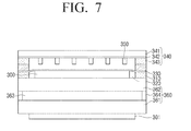
- the touch sensor 151 may be included in the first and second displays 190a and 190b, respectively, along with a display panel 235, as illustrated in FIG. 6 .
- the geomagnetic sensor 152 is a sensor that senses azimuth by detecting a flow of a magnetic field.
- the geomagnetic sensor 152 detects azimuth coordinates of the multi display device 100 and detects a direction in which the multi display device 100 is placed based on the azimuth coordinates.
- the direction in which the multi display device 100 is placed is recognized as corresponding control input and the controller 130 performs corresponding output.
- the acceleration sensor 153 is a sensor that senses acceleration of the multi display device 100, and sets virtual x, y, and z axes on the multi display device 100 and senses a value of acceleration of gravity that changes according to an inclination of each axis.
- the acceleration sensor 153 may be used to detect acceleration (i.e., dynamic acceleration) of a moving object, but may be used mainly to detect the acceleration of gravity.
- the hinge sensor 156 may sense an angle or a motion of the hinge 185.
- the proximity sensor 155 may sense whether an object approaches the multi display device 100 of the user. The proximity sensor will be explained in detail below.
- the sensor 150 of the multimedia display device 100 may further include at least one of a gravity sensor that senses in which direction gravity is acted, a gyro sensor that recognizes six axes in total by adding rotation to an existing acceleration sensor, an orientation sensor that automatically senses horizontal and vertical frames of a content such as an image and automatically rotates and arranges the content, an illuminance sensor that senses an amount of ambient light around the multi display device 100, an altitude sensor that measures atmospheric pressure, an RGB sensor that senses a color of an object, a distance sensor that measures a distance using ultrasonic wave or infrared rays, and a hall sensor that uses a change in a voltage according to a magnitude of a magnetic field.
- a gravity sensor that senses in which direction gravity is acted
- a gyro sensor that recognizes six axes in total by adding rotation to an existing acceleration sensor
- an orientation sensor that automatically senses horizontal and vertical frames of a content such as an image and automatically rotates and arranges the content
- the sensor 150 detects a state of each sensor, generates a signal corresponding to the detection, and transmits the signal to the controller 130.
- the sensors of the sensor 150 may be added or deleted according to performance of the multi display device 100.
- the inputter/outputter 160 is an element that performs input/output using a screen or other external connecting ports. Specifically, the inputter/outputter 160 receives an input signal that is transmitted from an inputting means connected to the multi display device 100 such as a mouse, a keyboard, or a joystick, or a wireless inputting means such as a remote controller, and transmits the input signal to the controller 130. Also, the inputter/outputter 160 may output various signals or data that is generated by the controller 130 to an external device.
- the inputter/outputter 160 includes a button 161, a microphone 162, a speaker 163, and a vibration motor 164.
- At least one button 161 may be formed on a front surface, a side surface, or a rear surface of the housing of the multi display device 100 in the form of a push type or a touch type, and may include at least one of a power/lock button, a volume control button, a menu button, a home button, a back button, and a search button.
- a power/lock button When the button 161 is pressed, a corresponding control command is generated and transmitted to the controller 130.
- the controller 130 controls the operation of the multi display device 100 according to the control command.
- the microphone 162 receives a voice or a sound under the control of the controller 130 and generates an electric signal.
- the speaker 163 may output a sound corresponding to various signals of the cellular communication module 111, the wireless LAN module 112, the short-range communication module 113, the multimedia part 120, or the photographer (for example, a radio signal, a broadcast signal, a digital audio file, a digital moving image file, or photographing) to the outside of the multi display device 100.
- a radio signal for example, a radio signal, a broadcast signal, a digital audio file, a digital moving image file, or photographing
- the speaker 163 may output a sound corresponding to a function of the multi display device 100 (for example, a button sound or a ringtone corresponding to calling).
- a single speaker 163 or a plurality of speakers 163 may be formed on an appropriate location or locations of the housing of the multi display device 100.
- the speaker 163 may include an internal speaker module that is formed on a location that is in the proximity to user's ears when the user is on the phone, and an external speaker module that has higher output suitable to reproduce audio/video files or to allow a user to view a broadcast, and is disposed on an appropriate location of the housing of the multi display device 100.
- the vibration motor 164 converts an electric signal into a mechanical vibration under the control of the controller 130. For example, when a voice call is received from another device (not illustrated), the multi display device 100 that is in a vibration mode drives the vibration motor 164.
- a single vibration motor 164 or a plurality of vibration motors 164 may be disposed in the housing of the multi display device 100.
- the vibration motor 164 may be operated in response to a user's touch gesture sensed on the first or second display 190a or 190b, and a continuous touch motion sensed on the first or second display 190a or 190b.
- the storage 170 is configured to store various programs and data such as an operating system (OS) or an application.
- OS operating system
- application application
- the storage 170 may store an operating system (OS) program to control the operation of the multi display device 100.
- OS operating system
- the storage 170 may store an operating system (OS) program to control the operation of the multi display device 100.
- OS operating system
- the storage 170 may also store an application program that is managed by the OS, performs the operation of the multi display device 100 using resources of the OS, and provides a user interface.
- the application program is read out from the storage by the OS according to a user's execution command, and is converted into an executable format and performs various operations.
- the storage 170 may store various multimedia data that are processed by the controller 130, content data, and data that is received from an external source. That is, the storage 170 may store signals, information, or data that are input/output according to the operations of the cellular communication module 111, the wireless LAN module 112, the short-range communication module 113, the connector 114, the GPS module 115, the multimedia part 120, the photographer 140, the sensor 150, the inputter/outputter 160, and the first and second displays 190a and 190b, respectively, under the control of the controller 130.
- the storage 170 may store information that is transmitted according to a result of sensing by the input pen 500, or may store a result of analyzing the information by the controller 130.
- the storage 170 may be implemented by using at least one of a read only memory (ROM), a random access memory (ROM), a memory card (for example, an SD card or a memory stick) that is mountable in the multi display device 100 or dismountable from the multi display device 100, a non-volatile memory, a volatile memory, a hard disk drive (HDD), or a solid state drive (SSD), but is not limited thereto.
- ROM read only memory
- ROM random access memory
- a memory card for example, an SD card or a memory stick
- HDD hard disk drive
- SSD solid state drive
- the power supply 180 supplies power to be used in the multi display device 100.
- the power supply 180 may be implemented by a rechargeable battery, and may further include a voltage converter to convert an external power source and supply it to a rechargeable battery.
- the power supply 180 may supply power to the multi display device 100 in various modes such as a maximum performance mode, a general mode, a power saving mode, and a standby mode under the power control of the controller 130.
- the first and second displays 190a and 190b are included in the sensor 150 as described above, and are configured to output images stored in a frame buffers.
- the first and second displays 190a and 190b, respectively, may display multimedia contents, images, moving images, and texts under the control of the controller 130.
- the first display 190a and the second display 190b are physically separated from each other. Display screens displayed on the first display 190a and the second display 190b may be controlled independently. For example, resolution of the first display 190a and resolution of the second display 190b are individually set. Also, screen enlargement, screen rotation, screen movement, and screen split of the first display 190a and the second display 190b may be individually performed.
- the first display 190a and the second display 190b may display a single display screen using a virtual integrated frame buffer.
- the first and second displays 190a and 190b are display devices that display execution screens of various applications executable by the controller 130 (for example, call, data transfer, broadcast, and camera) and provide user interfaces corresponding to the applications.
- the first and second displays 190a and 190b, respectively, may include the above-described touch sensor 151.
- the first and second displays 190a and 190b, respectively may receive input of at least one touch gesture through a user's body (for example, fingers including the thumb) or an inputting means that can be sensed (for example, a stylus pen).
- Such a user interface may include a predetermined touch region, a soft key, and a soft menu.
- An electronic signal corresponding to at least one touch gesture that is input through the user interface may be transmitted to the first and second display 190a and 190b, respectively, through an LCD controller (not illustrated).
- the first and second displays 190a and 190b, respectively may sense a continuous touch motion and may transmit an electronic signal corresponding to a continuous or discontinuous touch motion to the LCD controller.
- the touch sensor 151 may be implemented by a resistive method, a capacitive method, an infrared-ray method, or an acoustic wave method.
- the first and second displays 190a and 190b convert a sensing signal regarding a user operation that is sensed through the touch sensor into a digital signal (for example, x and y coordinates), and transmits the digital signal to the controller 130.
- the controller 130 may perform a control operation corresponding to the user operation that is input through the first and second displays 190a and 190b, respectively, using the received digital signal. For example, the controller 130 may select a soft key that is displayed on the first and second displays 190a and 190b, respectively, or may execute an application corresponding to the soft key in response to the user operation.
- the above-described user gesture is not limited to direct contact of the user's body or a touch inputting means with the first and second displays 190a and 190b, respectively, and may be made in a non-contact method. Sensitivity of the user operation detectable by the first and second displays 190a and 190b, respectively, may be changed according to performance or a configuration of the multi display device 100.
- the touch gesture includes various types of user gestures that can be sensed by the multi display device 100 by directly contacting a touch screen or approaching the touch screen.
- the touch gesture may include a user's operation of selecting a single position or a plurality of continuous positions on the touch screen using user's finger of the left and right hands (in particular, an index finger), user's thumb, or an object that can be sensed by the touch screen (for example, a stylus pen).
- Table 1 illustrates various types of gestures that are made using a single finger.
- the types of gestures made using a single finger may include tap, touch & hold, double tap, drag, drag & drop, and flick, but is not limited thereto.
- the tap is a user's operation of touching the touch screen slight and then raising the user's finger.
- the touch & hold is a user's operation of touching the touch screen and keeping touching for a long time.
- the double tap is a user's operation of tapping twice quickly.
- the drag is a user's operation of touching and moving in one direction while still touching, and the drag & drop is a user's operation of touching an object on the touch screen and dragging it from one position to the other position.
- the flick is a user's operation of dragging rapidly.
- Table 2 illustrates various types of gestures that are made using two fingers.
- the types of gestures made using two fingers may include two finger tap, touch & spread, pinch out, pinch in, two finger drag, cross two finger, and touch & rotate, but are not limited thereto.
- the two finger tap is a user's operation of tapping with two fingers simultaneously
- the touch & spread is a user's operation of pressing the touch screen with two fingers simultaneously and moving only one finger in a straight line without moving the other finger.
- the pinch out is a user's operation of touching the touch screen with two fingers simultaneously and then moving the two fingers further apart
- the pinch in is a user's operation of touching the touch screen with two fingers simultaneously and then moving the two fingers closer together.
- the two finger drag is a user's operation of dragging with two fingers in the same direction
- the cross two finger is a user's operation of dragging with two fingers closer together, crossing the two fingers, and then dragging further apart.
- the touch & rotate is a user's operation of touching the touch screen with one finger and keeping touching (touch & hold), and touching with the other finger and rotating about fixed one finger while still touching.
- Table 3 illustrates various types of gestures that are made using two or more fingers, and a type of gesture that is made using the user's palm.
- the types of gestures made using two or more fingers may include three finger touch, four finger touch, and five finger touch. Also, gestures such as tap, drag, and rotate may be performed using two or more fingers as illustrated in tables 1 and 2.
- the controller 130 When one of the above-described various touch gestures is recognized, the controller 130 performs an operation corresponding to the touch gesture.
- the controller 130 may execute an application, a widget, or a web browser stored in the storage 170, and may display an execution screen thereof on at least one of the first and second displays 190a and 190b, respectively.
- the bodies of the multi display device 100 are connected to each other by means of the hinge 185 in the above-described exemplary embodiments, but the bodies may be connected to each other by means of a flexible connector instead of the hinge 185.
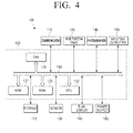
- FIG. 4 is a block diagram illustrating a detailed configuration of a multi display device 100 according to various exemplary embodiments of the present invention.
- the multi display device 100 includes a communicator 110, a multimedia part 120, a controller 130, a photographer 140, a sensor 150, an inputter/outputter 160, a storage 170, a power supply 180, and a multi display part 190.
- the communicator 110 is configured to communicate with an external device according to various communication methods as described above. Since the communicator 110 has been described above in detail, a redundant explanation thereof is omitted.
- the multimedia part 120 is configured to reproduce moving image contents, audio contents, or other various multimedia contents.
- the multimedia part 120 processes a multimedia content using a parser or a codec, and reproduces the content.
- the photographer 140 is configured to photograph an image according to user manipulation.
- a plurality of photographers 140 may be provided in the multi display device 100.
- a first photographer may be provided in the first body in which the first display 190a is provided
- a second photographer may be provided in the second body 4 in which the second display 190b is provided.
- the controller 130 may store an image that is photographed by the photographer 140, or may attach the image to a mail, a messenger, or a message and may transmit the image to the outside.
- the controller 130 may recognize a user's motion gesture by analyzing the image photographed by the photographer 140, and may perform a control operation corresponding to the motion gesture.
- the inputter/outputter 160 is an element that performs input/output using a screen or other external connecting ports. Specifically, the inputter/outputter 160 receives an input signal that is transmitted from an inputting means connected to the multi display device 100 such as a mouse, a keyboard, or a joystick, or a wireless inputting means such as a remote controller, and transmits the input signal to the controller 130. Also, the inputter/outputter 160 may output various signals or data that is generated by the controller 130 to an external device.
- the sensor 150 is configured to sense various state changes such as a user's touch on the multi display device 100, a user motion, and a motion of the multi display device 100.
- the sensor 150 will be explained again in detail below.
- the power supply 180 is configured to supply power to each element of the multi display device.
- the controller 130 controls overall operations of the above components.
- the controller 130 includes a central processing unit (CPU) 131, a graphics processing unit (GPU) 133, a random access memory (RAM) 135, a read only memory (ROM) 137, and a system bus 139.
- the CPU 131 controls not only the internal elements of the controller 130 but also the elements of the multi display device 100.
- the CPU 131, the GPU 133, the RAM 135, and the ROM 137 are connected to one another through the system bus 139 and may exchange various data or signals with one another.
- the ROM 137 stores a set of commands to boot a system.
- the CPU 131 copies an OS stored in the storage 170 into the RAM 135 according to a command stored in the ROM 137, executes the OS, and boots the system.
- the CPU 131 copies various application programs stored in the storage 170 into the RAM 135, and performs various operations by executing the application programs copied into the RAM 135.
- the CPU 131 may perform various operations by executing the application programs stored in the storage 170.
- the storage 170 may store information on a toolset that is usable in each application.
- the CPU 131 displays a toolset using the toolset information stored in the storage 170. Specifically, when an event in which a toolset display menu is selected, an event in which a user's body or a stylus pen 480o approaches or touches, and an event in which the first and second displays 190a and 190b are unfolded by a predetermined angle by the hinge 185 are generated, the toolset may be displayed.
- the GPU 133 may include a decoder, a renderer, and a scaler. Accordingly, the GPU 133 decodes a stored content, renders the decoded content and forms a frame, and scales a size of the formed frame according to a display size under the control of the display controller (not illustrated). If the frame is to be displayed on one of the first and second displays 190a and 190b, respectively, the frame is scaled according to the size of one display, and, if the frame is to be displayed on both the two displays, the frame is scaled according to the entire display size. The GPU 133 provides the processed frame to the display and displays it.
- the controller 130 may further include various types of interfaces for interfacing with surrounding elements.
- the CPU 131 accesses a web server through a network interface (not illustrated).
- the CPU 131 controls the GPU 133 to configure a web page screen and display the configured web page screen on at least one of the above-described first and second displays 190a and 190b, respectively.
- the controller 130 determines whether the user manipulation is intended. When it is determined that the user manipulation is intended, the controller 130 reads out information on an operation corresponding to the user manipulation from the storage 170, and performs an operation corresponding to the information.
- the above-described operation of the controller 130 may be implemented by executing various programs stored in the storage 170.
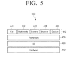
- FIG. 5 is a view illustrating a system hierarchy of the multi display device 100 according to an exemplary embodiment of the present invention.
- the multi display device 100 includes hardware 410, an OS 420 to drive the hardware, an application layer 440 including application layers 441 through 445 that are managed by the OS as processes and provide user services using resources, and a framework layer 430 to intermediate between the OS and the application.
- the OS 420 controls an overall operation of the hardware 410 and manages the hardware 410 and a process corresponding to each application. That is, the OS 420 is a layer that manages the hardware and performs a basic function such as memory and security.
- the OS 420 includes modules such as a display driver to drive a multi display, a communication driver to exchange data, a camera driver to drive a camera, an audio driver to drive an audio unit, and a power supply manager. Also, the OS 420 may include an API library and a runtime that are accessible by a developer. The OS 420 processes a call of an application and operates the hardware according to a result of the processing.
- the framework layer 430 exists as an upper layer of the OS 420.
- the framework 430 connects the application layer 440 and the OS layer 420. That is, the framework layer 430 includes a location manager, a notification manager, and a frame buffer to display an image on a touch screen.
- the application layer 440 exists as an upper layer of the framework layer 430 to perform various functions of the multi display device 100.
- the application layer 440 may include a call application 441, a multimedia application 442, a camera application 443, a browser application 444, and a gesture application 445.
- the applications 441 through 445 provide a user interface, and receive a command from the user and transmit the command to the OS 420 through the framework, or request resources of the OS 420.
- the OS 420 processes a system call and manages tasks of many applications.
- the OS 420 operates many hardware configurations including the first display 190a and the second display 190b according to a result of processing the system call.
- FIG. 6 is a view illustrating a circuit configuration of a display of the first display 190a (or alternatively, the second display 190b of FIG. 2 ), according to an exemplary embodiment of the present invention.
- the first display 190a will be mainly described, but the second display 190b has the same configuration as that of the first display 190a and thus is operated in the same way.
- the display may include the first display 190a and the second display 190b as described above. Also, the display may further include a touch screen.
- an image output circuit of the first display 190a may include a timing controller 231, a gate driver 232, a data driver 233, a voltage driver 234, and a display panel 235.
- the timing controller 231 receives a clock signal (DCLK), a horizontal sync signal (Hsync), and a vertical sync signal (Vsync), which are suitable to correspond to a resolution of the touch screen, from an external source, generates a gate control signal (scan control signal) and a data control signal (data signal), rearranges input R, G, and B data, and provides the R, G, and B data to the data driver 233.
- DCLK clock signal
- Hsync horizontal sync signal
- Vsync vertical sync signal
- the timing controller 231 may generate a gate shift clock (GSC), a gate output enable (GOE), and a gate start pulse (GSP) regarding the above gate control signal.
- GSC is a signal to determine a time at which a thin film transistor (TFT) connected to light emitting elements such as R, G, and B organic light emitting diodes (OLEDs) is turned on and/or off.
- TFT thin film transistor
- OLEDs organic light emitting diodes
- the GOE is a signal to control output of the gate driver 232
- the GSP is a signal to indicate a first driving line of a screen out of one vertical sync signal.
- the timing controller 231 may generate a source sampling clock (SSC), a source output enable (SOE), and a source start pulse (SSP) regarding the data control signal.
- SSC source sampling clock
- SOE source output enable
- SSP source start pulse
- the SSC is used as a sampling clock to latch data in the data driver 233, and determines an operation frequency of a data drive IC.
- the SOE transmits the data latched by the SSC to the display panel 235.
- the SSP is a signal to inform a latch or sampling start of data corresponding to the one horizontal synchronization duration.
- the gate driver 232 generates a scan signal and is connected to the display panel 235 through scan lines S1, S2, S3, ..., Sn).
- the gate driver 232 applies a gate on/off voltage (Vgh/Vgl), which is provided from the voltage driver 234, to the display panel 235 according to the gate control signal generated by the timing controller 231.
- the gate on voltage (Vgh) is transmitted to a gate line 1 (GL1) through a gate line N (GLn) in sequence to realize a unit frame image on the display panel 235.
- the data driver 233 generates a data signal and is connected to the display panel 235 through data lines (D1, D2, D3, ..., Dm).
- the data driver 233 completes scaling and inputs the RGB data of the image frame to the display panel 235 according to the data control signal generated by the timing controller 231.
- the data driver 233 converts the image data of the RGB, which is provided from the timing controller 231 in series, into data in parallel, converts digital data into an analogue voltage, and provides image data corresponding to one horizontal line to the display panel 235. This process is performed with respect to each horizontal line in sequence.
- the voltage driver 234 generates driving voltages and transmits them to the gate driver 232, the data driver 233, and the display panel 235. That is, the voltage driver 234 receives a supply voltage from an external source, that is, an alternating current (AC) voltage of 110V or 220V, and generates a power voltage (VDD) necessary to drive the display panel 235 and provides the power voltage, or provides a grounded voltage (VSS). Also, the voltage driver 234 may generate the gate on voltage (Vgh) and provides it to the gate driver 232. To achieve this, the voltage driver 234 may include a plurality of voltage driving modules (not illustrated) that are individually operated.
- the plurality of voltage driving modules may be operated to provide different voltages under the control of the controller 130, and the controller 130 may control the voltage driver 234 such that the plurality of voltage driving modules provide different driving voltages according to pre-set information.
- the plurality of voltage driving modules may provide different first voltages and a second voltage that is set as default according to pre-set information under the control of the controller 130.
- the voltage driver 234 may include a plurality of voltage driving modules corresponding to a plurality of regions into which the display panel 235 is divided.
- the controller 130 may control the plurality of voltage driving modules to provide different first voltages, that is, ELVDD voltages according to screen information (or input image information) of the plurality of regions. That is, the controller 130 may control a level of the ELVDD voltage using an image signal that is input to the data driver 233.
- the screen information may be at least one of brightness and grayscale information of the input image.
- the display panel 235 includes a plurality of gate lines (GL1 through GLn) and a plurality of data lines (DL1 through DLn) that intersect to define a pixel region.
- R, G, and B light emitting elements such as OLEDs may be formed on a pixel region 236 where the gate lines and the data lines intersect.
- a switching element that is, a TFT is formed on a certain region of the pixel region 236, specifically, a corner.
- grayscale voltages are provided to the R, G, and B light emitting elements from the data driver 233.
- the R, G, and B light emitting elements provide light according to an amount of electricity provided based on the grayscale voltages. That is, if much electricity is provided, the R, G, and B light emitting elements provides a large amount of light.
- the first display 190a includes an image outputter and a touch screen.
- the image outputter includes a display panel 360 in which an upper substrate 362 and a lower substrate 361 are formed in close contact with each other, an upper polarizing plate 300 that is formed on the upper substrate 362 of the display panel 360, and a lower electrode 310 that is formed on an edge of the polarizing plate 300.
- the image outputter further includes a lower polarizing plate 301 that is formed on the lower substrate 361.
- a liquid crystal layer 363 may be formed between the upper substrate 362 and the lower substrate 361.
- the upper substrate 362 and the lower substrate 361 include a display region to display an image and a border region that is formed along an edge of the display region.
- the display region of the lower substrate 361 includes a plurality of gate lines and a plurality of data lines, a thin film transistor that is formed on a region where the plurality of gate lines and the plurality of data lines intersect, and a pixel electrode that is connected to the thin film transistor.
- a sustain electrode that partially overlaps the pixel electrode may be provided.
- a plurality of pads may be formed on the border region of the lower substrate 361 to be connected with the gate lines and the data lines.
- the upper substrate 362 and the lower substrate 361 may be sealed by a sealing member 364 such as a sealant.
- the sealing member 364 may be formed along the border region of the upper substrate 362 and the lower substrate 361.
- the touch screen includes a lower transparent electrode 330 that is connected to the lower electrode 310 and is formed on the upper polarizing plate 300, a touch pad 340 in which an upper transparent electrode 342 is provided and that is attached to the upper substrate 362, and a protrusion 350 that is provided between the upper transparent electrode 342 and the lower transparent electrode 330.
- the touch pad 340 includes a base film 341, the upper transparent electrode 342 that is formed on the base film 341, and an upper electrode 343 that is formed on the upper transparent electrode 342.
- the touch pad 340 When the touch pad 340 is pressed by a predetermined external force, the protrusion 350 of the region to which the force is applied is brought into close contact with the lower transparent electrode 330, and accordingly, the lower transparent electrode 330 and the upper transparent electrode 342 are electrically connected to each other.
- the currents flowing in the upper transparent electrode 342 and/or the lower transparent electrode 330 are changed by the electrical connection, and this change is sensed by a separate sensing means (not illustrated).
- the sensing means transmits a sensed signal to the controller 130, which is separately provided.
- the controller 130 generates coordinates of the region in which the flow of the currents is changed using the sensed signal, and transmits the coordinates to a predetermined driver (not illustrated).
- the driver may perform the same operation as manipulating an image displayed on the display panel 360 using an input tool such as a mouse in response to the input coordinates.
- the multi display device 100 may include an image frame buffer having various configurations due to its specific characteristics.
- the image frame having various potential configurations will be described.
- the display driver 175 includes a first frame buffer 175a-1, a first display driver 175a-2, a second frame buffer 175b-1, and a second display driver 175b-2. That is, the first and second displays 190a and 190b, respectively, may include respective frame buffers 175a-1 and 175b-1 and respective display drivers 175a-2 and 175b-2.
- the first frame buffer 175a-1 is configured to buffer an image frame to be displayed on the first display 190a
- the second frame buffer 175b-1 is configured to buffer an image frame to be displayed on the second display 190b.
- an image frame that has been digital signal processed by the GPU 133 may be stored in the first and second frame buffers 175a-1 and 175b-1 in a bitmap format.
- a buffering region of each of the frame buffers 175a-1 and 175b-1 is assigned according to a maximum pixel size supportable by each of the first and second displays 190a and 190b, respectively.
- the first display driver 175a-2 analyzes the image frame stored in the first frame buffer 175a-1 and converts the image frame into a first image source signal.
- the first display driver 175a-2 provides the first image source signal to the first display 190a and drives the first display 190a to display the image frame.
- the second display driver 175b-2 analyzes the image frame stored in the second frame buffer 175b-1, converts the image frame into a second image source signal, provides the second image source signal to the second display 190b, and displays the image frame.
- Such two frame buffers may be suitable to process the image frame corresponding to each of the first and second displays 190a and 190b, respectively, in parallel.
- a parallel processor outputs an image signal corresponding to each of the displays 190a and 190b, respectively, image output efficiency can be improved.
- first and second displays 190a and 190b may use a single integrated frame buffer 175-1 rather than using the first frame buffer 175a-1 and the second frame buffer 175b-1 provided separately, as illustrated in FIG. 9 .
- FIG. 9 is a block diagram illustrating a configuration of the multi display device 100 that controls operations of the first and second displays 190a and 190b, respectively, using the integrated frame buffer 175-1.
- the integrated frame buffer 175-1 may be assigned a size larger than a maximum resolution of the first and second displays 190a and 190b.
- the integrated frame buffer 175-1 may be assigned a storage region corresponding to a frame buffer size capable of displaying a resolution of 1024*1600.
- a first region of the integrated frame buffer 175-1 stores a first image frame to be displayed on the first display 190a, and a second region stores a second image frame to be displayed on the second display 190b.
- a display driver 175-2 provides the first or second image frame to the first display 190a or the second display 190b using addresses of the first image frame and the second image frame stored in the integrated frame buffer 175-1, and drives each of the first and second displays 190a and 190b.
- the sensor 150 of the multi display device 100 may include the proximity sensor 155.
- the proximity sensor 155 may include the proximity sensor 155.
- a configuration and an operation of the proximity sensor 155 will be explained.
- FIG. 10 is a view illustrating an example of a method of sensing hovering according to an exemplary embodiment of the present invention.
- the user may input a control command to the multi display device 100 only by moving his/her finger or other user objects close to a touch screen without directly touching the touch screen.
- the multi display device 100 may sense hovering using the proximity sensor 155.
- the hovering may be recognized as a single touch gesture when the user does not directly touch the touch screen and a motion is recognized within a predetermined effective recognition range on space.
- a display 290 includes an infrared ray (IR) source 291 and an IR sensor 292 to recognize hovering.
- IR infrared ray
- the IR source 291 emits infrared rays to a surface of the display 290. Specifically, the IR source 291 is disposed on the lower portion of the display 290 that displays an image, and emits infrared rays to the surface of the display 290. There may be a predetermined region in which the approach of a user object 50 is recognized on the surface of the display 290. This region is an effective recognition region 5 in which hovering is recognized.
- the user object refers to a means to input a command to the multi display device 100, and may be a part of the user's body, such as a hand or finger.
- the IR sensor 292 senses infrared rays reflected from the approaching user object 50, and generates an IR scan image. Specifically, the IR sensor 292 may generate the IR scan image corresponding to the infrared rays reflected from the approaching user object 50 using a plurality of IR sensing elements, which are arranged in an array form. The multi display device 100 may sense hovering input using the generated IR scan image.
- FIG. 11 is a view illustrating an example of a method of sensing hovering using an input pen 500 according to an exemplary embodiment of the present invention.
- the input pen 500 may include a magnetic field coil therein.
- the multi display device 100 may further include a magnetic field sensor 295 to sense a change in the magnetic field according to proximity of the magnetic field coil to a display 290, which includes an infrared ray (IR) source 291 and an IR sensor 292 to recognize hovering of the input pen 500. Since a point over which the input pen 500 hovers has its magnetic field changed due to the magnetic field coil of the input pen 500, the magnetic field sensor 295 may sense hovering of the input pen 500 at a corresponding point. There may be a predetermined region in which the approach of the input pen 500 is recognized by a surface of the display 290. This region is an effective recognition region 5a in which hovering of the input pen 500 is recognized.
- the proximity sensor 155 of FIG. 3 also senses the hovering, but, when both the proximity sensor 155 and the magnetic field sensor 295 sense hovering of the user object, the result of sensing by the proximity sensor 155 is disregarded. Accordingly, when the magnetic field sensor 295 senses the hovering of the input pen 500, the multi display device 100 is regarded as being in a pen input mode and displays a corresponding menu item or screen.
- the controller 130 may be operated in a keyboard input mode to display a soft keyboard on at least one of the first display 190a and the second display 190b.
- FIG. 12 is a perspective view illustrating the multi display device 100 in detail according to an exemplary embodiment of the present invention.
- the multi display device 100 includes the first and second displays 190a and 190b, respectively, which are connected to each other by means of a hinge 185.
- the multi display device 100 includes first and second bodies 2 and 4, respectively, which are connected to each other by the hinge 185 and are movable relative to each other.
- the first display 190a may be provided on one surface of the first body 2, and at least one physical button 161 may be provided on one side surface of the first display 190a.
- the second display 190b may be provided on one surface of the second body 4, and at least one physical button 161' may be provided on one side surface of the second display 190b.
- the physical buttons 161 and 161' include at least one of a push button and a touch button.
- the first display 190a that is provided on the first body 2 including a speaker (not illustrated) and a microphone (not illustrated) is operated as a main screen
- the second display 190b that is provided on the second body 4 that does not include such a member may be operated as a sub screen.
- the first body 2 includes a first camera 141 and the second body 4 includes a second camera 142.
- the first and second displays 190a and 190b respectively, display screens in a landscape mode.
- the multi display device 100 When the multi display device 100 is configured to have the first body 2 and the second body 4 connected to each other by means of the hinge 185 and move relative to each other, the multi display device 100 may be any device like a mobile phone, a laptop computer, a tablet PC, and a portable multimedia player (PMP).
- the first display 190a and the second display 190b are provided on the first body 2 and the second body 4, respectively, the following explanation may also be applied to a device in which a touch screen display is provided on only one of the two panels.
- at least one of function buttons 161 on the side surfaces of the first and second displays 190a and 190b, respectively, may be omitted.
- the first body 2 and the second body 4 are connected to each other by means of the hinge 185, they may be connected to each other by means of other elements only if the first body 2 and the second body 4 can be folded in relative to each other.
- the hinge 185 may include two hinges that are formed at opposite edges of a connection portion between the first body 2 and the second body 4. Also, the hinge 185 may be a single hinge that is disposed on the entire connection portion between the first body 2 and the second body 4.
- the multi display device 100 includes a display device that includes the first display 190a and the second display 190b that are physically or graphically separated from each other, and may support various screen modes as illustrated in FIGS. 13 through 17 using the first and second displays 190a and 190b, respectively.
- FIGS. 13 through 17 are views illustrating screen modes according to a relative angle between the first body 2 and the second body 4 of the multi display device 100 according to an exemplary embodiment of the present invention.
- a relative angle ( ⁇ ) is a rotation angle of the second body 4 that is rotated with reference to the first body 2 in a predetermined direction (for example, a counter clockwise direction).
- the relative angle ( ⁇ ) may be detected using a hinge sensor that is embedded within the hinge 185.
- the hinge sensor may include at least one of a hall sensor, a pressure sensor, an inductive sensor, an electric content sensor, and an optical sensor, but is not limited thereto, and may recognize the relative angle ( ⁇ ) by detecting a movement and a relative location of the hinge.
- the relative angle ( ⁇ ) may be recognized by the geomagnetic sensor or the acceleration sensor 153 detecting locations of the first and second bodies 2 and 4.
- FIG. 13 is a perspective view illustrating the multi display device 100 when it is folded with reference to the hinge 185.
- the first body 2 and the second body 4 are in contact with each other with the first and second displays 190a and 190b, respectively, on the first body 2 and the second body 4 facing in the opposite direction. That is, the first body 2 and the second body 4 are completely folded out in the opposite direction.
- This state may be called a single mode.
- the relative angle ( ⁇ ) is 0°.
- the multi display device is recognized as being in the single mode.
- the single mode may be usefully used when the multi display device 100 is not in use and is in a locked state or may be used in a call application.
- the first display 190a on a front surface displays a task screen of at least one application
- the second display 190b on a rear surface may be turned off. Some applications may turn on the second display 190b on the rear surface using an option menu.
- FIG. 14 illustrates the first body 2 and the second body 4 when they are parallel to each other, that is, are unfolded.
- the relative angle ( ⁇ ) is 180° or approaches 180° within a predetermined range.
- This state will be referred to as an expanding mode.
- the multi display device 100 determines that the first and second bodies 2 and 4 are unfolded.
- two task screens of two applications may be displayed on the first and second displays 190a and 190b, respectively, or two task screens of one application may be displayed on the first and second displays 190a and 190b, respectively.
- one task screen of one application may be may be broadly displayed over the first and second displays 190a and 190b, respectively.
- various view modes may be provided.
- the at least one of the first and second displays 190a and 190b may display a home screen.
- the expanding mode may be usefully used in an E-book and a moving image player application.
- FIG. 15 illustrates the relative angle ( ⁇ ) of the second body 4 to the first body 2 exceeding 180°, that is, illustrates the first and second displays 190a and 190b, respectively, which are slightly folded inward towards each other.
- this state will be referred to as a tool kit mode.
- the tool kit mode refers to a state in which the first and second displays 190a and 190b, respectively, are slightly folded inwards towards each other and may be useful when the multi display device 100 is used like a laptop computer.
- a task screen may be displayed on one display 190a, whereas various task environments such as a tool of a keyboard may be provided on the other display 190b.
- FIG. 16 illustrates a state in which the relative angle ( ⁇ ) of the second body 4 to the first body 2 is less than 180°, that is, the first and second displays 190a and 190b, respectively, are almost folded out to face each other in the opposite direction.
- This state is called a standing mode.
- the relative angle between the first and second bodies 2 and 4 is between 30° and 90°.
- this state will be referred to as a standing mode.
- the first and second displays 190a and 190b, respectively are folded out to face outwardly and the multi display device 100 may be placed on a bottom in a triangular shape.
- the standing mode is useful when the multi display device 100 is charged or used as a digital clock or album, or when the user views a private broadcast, movie, and moving image for a long time.
- the standing mode may be applied to an application that requires collaboration of two or more uses or interaction, for example, a video conference or a collaborative game.
- Some application may display a task screen only on the first display 190a of the front surface and may turn off the second display 190b of the rear surface in the standing mode.
- Some application may turn on the second display 190b on the rear surface using an option menu.
- FIG. 17 illustrates another exemplary embodiment of the present invention of the standing mode of FIG. 16 , and illustrates the multi display device 100 that is placed upright such that a part of the hinge 185 is in contact with a bottom.
- This state may be referred to as a portrait view mode.
- the relative angle between the first and second bodies 2 and 4 is between 30° and 90°, and, when it is determined that the multi display device 100 is placed upright by means of the acceleration sensor 153, the portrait view mode is recognized.
- the acceleration sensor 153 senses a rotation of the multi display device 100.
- the acceleration sensor 153 senses a switch between the portrait view mode in which the first and second displays 190a and 190b, respectively, of the multi display device 100 are placed on the left and right sides, and a landscape view mode in which the first and second displays 190a and 190b, respectively, are placed on the upper and lower sides.
- the portrait view mode may be applied to an application that has to provide different images to two or more users, for example, a video conference or a multi moving image player.
- FIGS. 18 and 19 are views illustrating placements of two cameras of the multi display device 100 according to an exemplary embodiment of the present invention.
- FIGS. 18 and 19 illustrate the multi display device 100 viewed from the front.
- FIGS. 18 and 19 are illustrating the placement of the cameras and thus omit components other than the cameras.
- the multi display device 100 includes the first body 2 and the second body 4, and the first body 2 includes the first display 190a and the second body 4 includes the second display 190b.
- the first body 2 and the second body 4 are connected to each other by means of the hinge 185 and are movable relative to each other.
- a first camera 141 may be placed on a center of a border region opposite the hinge 185 from among border regions of the first body 2.
- a second camera 142 may be placed on a center of a border region opposite the hinge 185 from among border regions of the second body 4.
- a first camera 141' may be placed on a center surface of a left border region of the first body 2, and a second camera 142' may be placed on a center surface of a left border region of the second body 4.
- the first and second cameras may be placed on center surfaces of right border regions of the first and second bodies 2 and 4, respectively.
- the first and second cameras may be placed on corner regions, or any other regions for that matter, of the first and second bodies 2 and 4, respectively.
- the multi display device 100 may be used in the horizontal direction as described above, and may be displayed in a vertical direction.
- the user performs a variety of input through the above-described multi display device 100, and the multi display device 100 performs output corresponding to the input.
- FIGS. 20 and 21 are views illustrating activating a toolset according to an exemplary embodiment of the present invention.
- FIG. 20 illustrates an operation of activating a toolset when the multi display device 100 is utilized in a vertical direction.
- View (a) of FIG. 20 illustrates an initial state of a display 2003
- view (b) of FIG. 20 illustrates a state in which a toolset 2005 is activated.
- the toolset 2005 is displayed as illustrated in view (b) of FIG. 20 .
- the multi display device 100 displays the toolset 2005 as a toolset UI of a semi-circular shape in a direction of dragging from the hinge region 2001 to the display 2003. Accordingly, as illustrated in view (b) of FIG. 20 , a screen of the dragged display 2003 is dimmed (2004).
- FIG. 20 illustrates the toolset activating operation when the multi display device 100 is utilized in the vertical direction.
- an operation of activating a toolset when the multi display device 100 is utilized in a horizontal direction will be explained with reference to FIG. 21 .
- View (a) of FIG. 21 illustrates an initial state of a display 2103
- view (b) of FIG. 21 illustrates a state in which a toolset 2105 is activated.
- a drag gesture 2102 moving from a shortcut region 2101 of a bezel toward the display 2103 to display the toolset 2105 is sensed, the toolset is displayed as illustrated in view (b) of FIG. 21 .
- the multi display device 100 displays the toolset 2105 having a toolset UI of a semi-circular shape in a direction of dragging from the shortcut region 2101 of the bezel to the display 2103.
- a screen of the dragged display 2103 is dimmed (2104).
- the toolset 2105 is activated on the shortcut region 2101 of the bezel in FIG. 21 , the toolset 2105 may be activated on the hinge region 2001 as illustrated in FIG. 20 even when the multi display device 100 is utilized in the horizontal direction.
- the toolset 2005 may be activated on the shortcut region 2101 of the bezel as illustrated in FIG. 21 .
- FIGS. 22 and 23 are views illustrating activating a lower level toolset when the multi display device 100 is utilized in the vertical direction and in the horizontal direction, respectively.
- a first toolset 2201 or 2301 is displayed on a display 2210 or 2310, respectively, by a user's toolset activating operation.
- a certain tool is selected from the first toolset 2201 or 2301 and a tap gesture 2202 or 2302, respectively, is sensed on the selected tool, the multi display device 100 progresses to view (b) of FIG. 22 and view (b) of FIG. 23 .
- the multi display device 100 in response to the tap gesture 2202 or 2302, respectively, the multi display device 100 separates the tool selected from the first toolset from the semi-circle of the first toolset, slightly extends the tool, and displays the tool (2203 or 2303), and activates a second toolset 2204 or 2304, respectively, which is a lower level toolset of the selected tool and displays the second toolset 2204 or 2304 on the display 2210 or 2310, respectively.
- a tap gesture 2205 or 2305 is sensed on the selected tool
- the multi display device 100 progresses to a screen of view (c) of FIG. 22 or view (c) of FIG. 23 , respectively.
- the multi display device 100 activates a third toolset 2206 or 2306, respectively, which is a lower level toolset of the selected tool and displays the third toolset 2206 or 2306 on the display 2210 or 2310, respectively, in response to the tap gesture.
- FIGS. 24 and 25 illustrate operation of making a lower level toolset disappear when the multi display device 100 is utilized in the vertical direction and in the horizontal direction, respectively.
- a first toolset, a second toolset, and a third toolset are displayed on a display 2410 or 2510, respectively, by extending lower level toolsets.
- a double tap gesture 2403 or 2503 is sensed on a margin 2402 or 2502 of the first toolset that is not within an activated tool region 2401 or 2501 of the first toolset
- the multi display device 100 progresses to view (b) of FIG. 24 and view (b) of FIG. 25 , respectively.
- the multi display device 100 makes the second toolset and the third toolset, which are lower level toolsets, and the activated tool region of the first toolset disappear from the display 2410 or 2510, respectively. Accordingly, only the first toolset 2404 or 2504 is displayed on the display 2410 or 2510, respectively.
- FIGS. 26 and 27 illustrate an operation of ending a toolset when the multi display device 100 is placed in the vertical direction and in the horizontal direction, respectively.
- the multi display device 100 progresses to a screen of view (b) of FIG. 26 or a view (b) of FIG. 27 .
- the multi display device 100 in response to the drag gesture, makes the first toolset disappear from the display and un-dims the dimmed display 2604 or 2704 and displays the screen 2605 or 2705, respectively.
- FIGS. 20 through 27 the operation of activating the toolset has been described on the assumption that the multi display device 100 is in the single mode. However, the toolset may be activated in the above-described various modes.
- FIGS. 28 through 30 explain an operation of executing a toolset in a tool kit mode 2800, an expanding mode 2900, and a standing mode 3000, respectively.
- FIG. 31 is a illustrating a first toolset according to various exemplary embodiments of the present invention.
- the first toolset refers to a basic toolset that is displayed by user's toolset activating manipulation.
- a first toolset of a semi-circular UI 3100-1 is divided into a display region 3110 that is displayed on the display, and a variable region 3120 that is not displayed on the display.
- the display region 3110 is a semi-circular part that is displayed when the toolset is activated, and a predetermined tool is placed on the display region 3110.
- the predetermined tool may be directly set by the user and may be a tool that is normally provided by the multi display device.
- the predetermined tool may represent a camera, a music player, a moving image shoot, a web browser, a gallery, an electronic book, a message, a memo, contact information, a calendar, and device settings.
- the variable region 3120 is the other semi-circular part that is not displayed when the toolset is activated, and a tool other than the predetermined tool, that is, a hidden tool, is placed. Such a variable region 3120 makes it possible to extend the tool in the future by updating the toolset.
- the first toolset 3100 is configured as a dial UI that is rolled up and down (3130), and the hidden tool of the variable region 3120 may be displayed on the display region 3110 by user's manipulation.
- a toolset may be divided into a display region and a variable region, and a hidden tool of the variable region may be displayed on the display according to user's manipulation.
- the first toolset may be displayed in at least one form of a card pocket UI 3100-2, a water drop UI 3100-3, and a quadrangular bar graph UI 3100-4.
- FIG. 32 is a view to explain a second toolset that is a lower level toolset of a first toolset according to various exemplary embodiments of the present invention.
- a second toolset 3230 which is a lower level toolset of the selected tool 3220, is displayed in a circular bar shape as if it slides down enclosing the first toolset (3240).
- the second toolset 3230 may be displayed as if it slides down enclosing the first toolset 3220 with an animation effect showing a rolling wave (3250).
- the second toolset 3230 may have a length of the bar changed according to a number of tools included in the second toolset 3230, and may be displayed in various layouts to be distinguished from the first toolset 3220.
- a second exemplary embodiment of the present invention includes a second toolset of the card pocket UI 3200-2 being displayed as if a card is drawn from the card pocket when one tool is selected from the first toolset.
- a third exemplary embodiment of the present invention includes a second toolset of a water drop UI 3200-3, such that when one tool is selected from the first toolset, unselected tools are put away in the selected tool as illustrated in FIG. 32 .
- Tools of the second toolset appear from the selected tool in a direction opposite to the direction in which the tools are put away in the first toolset, such that the second toolset is displayed.
- a third exemplary embodiment of the present invention includes a second toolset of a quadrangular bar graph UI 3200-4, such that when one tool is selected from the first toolset, the selected tool is moved toward the other display in the opposite direction of the display on which the first toolset is displayed, as illustrated in FIG. 32 .
- the second toolset is displayed on the display on which the selected tool is displayed.
- FIG. 33 is a view illustrating a third toolset that is a lower level toolset of a second toolset, and executing a tool according to various exemplary embodiments of the present invention.
- a semi-circular UI 3300-1 includes a tool 3320 that has already been selected from a first toolset 3310, such that a second toolset 3330 appears. Accordingly, when a tool 3335 is selected from the second toolset 3330, the semi-circular UI 3300-1 of the first exemplary embodiment of the present invention displays a third toolset 3340, which is a lower level toolset of the selected tool 3335, in a circular bar shape as if it slides down (3360) enclosing the second toolset 3330.
- the third toolset 3340 may have a length of the bar changed according to a number of tools included in the third toolset 3340.
- Another lower level tool under the third toolset 3340 may be displayed in a form of a circular button 3350.
- the lower level tool is displayed in the form of the circular button 3350 in the first exemplary embodiment of the present invention of the semi-circular UI 3300-1
- the lower level tool may be provided on a separate region as in the second exemplary embodiment of the present invention of a semi-circular UI 3300-2, and may perform a specific function.
- toolset operation will be explained with reference to the toolset of the semi-circular UI of the first exemplary embodiment.
- the toolset operation may also be applied to the second through fourth exemplary embodiments of the present invention.
- FIG. 34 is a view illustrating a flow of a toolset UI according to an exemplary embodiment of the present invention.
- a pre-defined touch gesture for example, a drag gesture 3401 is sensed
- the multi display device 100 progresses to view (b) of FIG. 34 .
- the multi display device 100 displays a first toolset 3402 in response to the drag gesture 3401.
- a certain tool 3412 is selected from the first toolset 3402 and a tap gesture is sensed on the selected tool 3412
- the multi display device 100 progresses to view (c) of FIG. 34 .
- the multi display device 100 activates the tool 3412 selected from the first toolset 3402 in response to the tap gesture (3403), and displays a second toolset 3404 as if it slides down enclosing the first toolset 3402.
- the multi display device 100 progresses to view (d) or (e) of FIG. 34 .
- the tool 3413 selected from the second toolset 3404 has a lower level toolset
- the multi display device 100 progresses to view (d) of FIG. 34
- a tool 3414 selected from the second toolset 3404 does not have a lower level toolset
- the multi display device 100 progresses to view (e) of FIG. 34 . Referring to view (d) of FIG.
- the multi display device 100 displays a third toolset 3406, which is a lower level toolset of the selected tool 3413, in response to the tap gesture 3405. Also, referring to view (e) of FIG. 35 , when the selected tool 3414 does not have a lower level toolset and performs on/off or +/-operations, the multi display device 100 displays a circular button 3409 along an outer edge of the circular bar of the second toolset 3404.
- a double tap gesture 3408 or 3411 is sensed on a margin 3407 or 3410 that is not within a tool activation region on the first toolset 3402 as illustrated in views (d) and (e) of FIG. 34
- the third toolset 3406 and the second toolset 3404 turn around towards the hinge 185 in sequence and disappear, and the multi display device 100 progresses to view (b) of FIG. 34 .
- FIG. 35 is a view illustrating executing a toolset when a single display-based application is driven according to an exemplary embodiment of the present invention.
- a single display-based application is driven on first and second displays 3501 and 3502, respectively.
- the multi display device 100 progresses to view (b) of FIG. 35 .
- the multi display device 100 displays a toolset 3520 on the second display 3502 to correspond to the direction of the drag gesture 3511, and dims the second display 3502 (3503).
- a user's gesture to select a 'setting' tool 3512 of the toolset 3520 is sensed, the multi display device 100 progresses to view (c) of FIG.
- a lower level toolset 3530 is displayed in response to the user's gesture 3512 to select the 'setting' tool 3512, and, when a user's gesture to select a 'GPS' tool 3513 is sensed on the lower level toolset 3530, the multi display device 100 progresses to view (d) of FIG. 35 .
- the multi display device 100 displays a GPS off state 3504 on the first display 190a via an alert message in response to the user's gesture to select the 'GPS' tool 3513.
- the selected toolset is always placed on an upper portion of the toolset UI, so that the same movement of the user's eyes is maintained and thus a consistent eye tracking environment can be provided to the user. For example, referring to view (b) and view (c) of FIG.
- the selected 'setting' tool 3512 is rolled up and is displayed on an upper portion of the second toolset 3520, and a second toolset 3530 that is a lower level toolset of the 'setting' tool 3512 is wiped down and displayed on at least a portion of an outer circumference of the second toolset 3520.
- FIG. 36 is a view illustrating executing a toolset when a dual display-based application is driven according to an exemplary embodiment of the present invention.
- the dual display-based application is different from the application in FIG. 35 in that a single application is driven on both first and second displays 3601 and 3602.
- a toolset 3620 may be executed on the dual display-based application in the same way as in the single display-based application.
- the second display 3602 on which the toolset is activated is dimmed (3603) such that the user can clearly recognize the toolset.
- the dual display-based application is driven on the first and second displays 3601 and 3602, respectively.
- the multi display device 100 progresses to view (b) of FIG. 36 .
- the multi display device 100 displays a toolset 3620 on the second display 3602 to correspond to the direction of the drag gesture 3611, and dims the second display 3602 (3603).
- a user's gesture to select a 'setting' tool 3612 of the toolset 3620 is sensed, the multi display device 100 progresses to view (c) of FIG.
- a lower level toolset 3630 is displayed in response to the user's gesture 3612 to select the 'setting' tool 3612, and, when a user's gesture to select a 'GPS' tool 3613 is sensed on the lower level toolset 3630, the multi display device 100 progresses to view (d) of FIG. 36 .
- the multi display device 100 displays a GPS off state 3604 on the first display 190a via an alert message in response to the user's gesture to select the 'GPS' tool 3613.
- FIG. 37 is a view illustrating a toolset dock according to an exemplary embodiment of the present invention.
- a single display-based application is driven on a first display 3701 and a second display 3702.
- a drag gesture 3711 performed in a direction from the first display 3701 toward the second display 3702 is sensed on a hinge region 3715
- the multi display device 100 progresses to view (b) of FIG. 37 .
- the multi display device 100 displays a toolset 3720 second display 3602 to correspond to the the direction of the drag gesture 3711, and dims the second display 3702 (3703).
- the multi display device 100 progresses to view (c) of FIG. 37 .
- view (c) of FIG. 37 in response to the user gesture 3712 to select the 'setting' tool 3712, the multi display device 100 displays a lower level toolset 3730.
- a long tap gesture is sensed on a 'display extension' tool 3713 of the lower level toolset 3730, the multi display device 100 progresses to view (d) of FIG. 37 . Referring to view (d) of FIG.
- the 'display extension' tool 3713 is activated in a movable form and a toolset dock 3730 is formed on an upper portion of the first display 3701, such that the 'display extension' tool 3713 is moved to a position 3731 for easy user-access.
- the toolset dock 3730 refers to a UI that stores and displays a selected tool in order to execute a tool that the user frequently uses swiftly.
- the toolset dock 3730 may swiftly execute the tool that he/she wants to use without executing the toolset.
- the toolset dock may be activated by a user's specific gesture while an application is being executed. For example, when a tap gesture is sensed on an upper portion of the application, the multi display device 100 activates the toolset dock on the upper portion of the application for a predetermined time.
- the toolset dock may vary a number of tools that can be stored according to user's settings.
- the toolset dock may have an individual toolset for each application and may provide a tool according to user's taste. Therefore, user' convenience in using an application can be improved.
- a toolset may include tools corresponding to an operation state of the multi display device 100. That is, the toolset may vary according to whether the multi display device 100 is displaying a home screen or is executing an application. In particular, when the multi display device 100 is executing an application, the multi display device 100 may display a different toolset according to a type of the application.
- FIGS. 38 to 47 are views illustrating examples of toolsets that are configured differently according to operation states of the multi display device 100, according to an exemplary embodiment of the present invention.
- FIG. 38 is a view illustrating a configuration example of a toolset that is displayed when an Internet browser tool is executed.
- an internet browser tool 3811 is normally activated to display a lower level toolset 3820 on a first toolset UI 3800.
- the lower level toolset 3820 of the Internet browser tool 3811 may include a setting tool 3821, a multi-window split tool 3822, a search tool 3823, an attachment tool 3824, a print tool 3825, and an information display tool 3826.
- a lower level toolset 3830 of the setting tool 3821 may include a display extension tool 3831, an upload setting tool 3832, a brightness adjustment tool 3833, a GPS setting tool 3834, a contrast adjustment tool 3835, a key setting tool 3836, and a security setting tool 3837.
- a lower level toolset reduction tool 3812 is also displayed on the first toolset UI 3800.
- the lower level toolset reduction tool 3812 is a tool to end a currently displayed lowest level toolset. For example, when the lower level toolset 3820 and the lower level toolset 3830 are both displayed, as illustrated in FIG. 38 , and the lower level toolset reduction tool 3812 is selected, the lower level toolset 3830 disappears.
- FIG. 39 is a view illustrating a toolset that is displayed when a music player is executed, according to an exemplary embodiment of the present invention.
- a music player tool 3911 and a lower level toolset reduction tool 3912 are displayed on a first toolset UI 3900.
- a lower level toolset 3920 of the music player tool 3911 may include a setting tool 3921, a playlist tool 3922, a music information view tool 3923, a search tool 3924, a volume adjustment tool 3925, and a trash bin tool 3926.
- a lower level toolset 3930 of the setting tool 3821 may include an equalizer setting tool 3931, a sound effect setting tool 3932, a playlist setting tool 3933, and a timer setting tool 3934.
- FIG. 40 is a view illustrating a toolset that is displayed when a moving image player is executed, according to an exemplary embodiment of the present invention.
- a moving image player tool 4001 and a lower level toolset reduction tool 4002 are displayed on a first toolset UI 4000.
- a lower level toolset 4010 of the moving image player tool 4001 may include a playlist tool 4011, a setting tool 4012, a screen adjustment tool 4013, a trash bin tool 4014, a volume adjustment tool 4015, and a search tool 4016.
- FIG. 41 is a view illustrating a toolset that is displayed when a camera is executed, according to an exemplary embodiment of the present invention.
- a camera tool 4101 and a lower level toolset reduction tool 4102 are displayed on a first toolset UI 4100.
- a lower level toolset 4110 of the camera tool 4101 may include a setting tool 4111, a flash setting tool 4112, a front and rear camera conversion tool 4113, a moving image shooting conversion tool 4114, a focus mode setting tool 4115, and a timer setting tool 4116.
- a lower level toolset 4120 of the setting tool 4111 may include a resolution setting tool 4121, a film setting tool 4122, a white balance setting tool 4123, and an ISO sensitivity setting tool 4124.
- FIG. 42 is a view illustrating a toolset that is displayed when a message is executed, according to an exemplary embodiment of the present invention.
- a message tool 4201 and a lower level toolset reduction tool 4202 are displayed on a first toolset UI 4200.
- a lower level toolset 4210 of the message tool 4201 may include a new message writing tool 4211, a received message view tool 4212, a trash bin tool 4213, a search tool 4214, and a setting tool 4215.
- FIG. 43 is a view illustrating a toolset that is displayed when a memo is executed, according to an exemplary embodiment of the present invention.
- a memo tool 4301 and a lower level toolset reduction tool 4302 are displayed on a first toolset UI 4300.
- a lower level toolset 4310 of the memo tool 4301 may include a new memo writing tool 4311, a memo list tool 4312, a print tool 4313, a trash bin tool 4314, a search tool 4315, and a setting tool 4316.
- a lower level toolset 4320 of the new memo writing tool 4311 may include an attachment tool 4321, a social network service (SNS) upload tool 4322, a pen setting tool 4323, a brush setting tool 4324, and an eraser setting tool 4325.
- SNS social network service
- FIG. 44 is a view illustrating a toolset that is displayed when a gallery is executed, according to an exemplary embodiment of the present invention.
- a gallery tool 4401 and a lower level toolset reduction tool 4402 are displayed on a first toolset UI 4400.
- a lower level toolset 4410 of the gallery tool 4401 may include a gallery list tool 4411, an SNS upload tool 4412, a shooting mode conversion tool 4413, a print tool 4414, a trash bin tool 4415, a search tool 4416, and a setting tool 4417.
- FIG. 45 is a view illustrating a toolset that is displayed when an e-book is executed, according to an exemplary embodiment of the present invention.
- an e-book tool 4501 and a lower level toolset reduction tool 4502 are displayed on a first toolset UI 4500.
- a lower level toolset 4510 of the e-book tool 4501 may include a list tool 4511, a search tool 4512, an SNS upload tool 4513, an e-book download tool 4514, a print tool 4515, and a setting tool 4516.
- FIG. 46 is a view illustrating a toolset that is displayed when contact information is executed, according to an exemplary embodiment of the present invention.
- a contact information tool 4601 and a lower level toolset reduction tool 4602 are displayed on a first toolset UI 4600.
- a lower level toolset 4610 of the contact information tool 4601 may include a new contact information addition tool 4611, a search tool 4612, a recent call contact information tool 4613, a contact information upload tool 4614, a contact information download tool 4615, a trash bin tool 4616, a bookmark tool 4617, and a setting tool 4618.
- FIG. 47 is a view illustrating a toolset that is displayed when a calendar is executed, according to an exemplary embodiment of the present invention.
- a calendar tool 4701 and a lower level toolset reduction tool 4702 are displayed on a first toolset UI 4700.
- a lower level toolset 4710 of the calendar tool 4701 may include a monthly schedule tool 4711, a weekly schedule tool 4712, a daily schedule tool 4713, a schedule list tool 4714, a schedule addition tool 4715, a D-day menu tool 4716, a trash bin tool 4717, and a setting tool 4718.
- the toolsets may vary according to various types of touching means corresponding to the multi display device 100.
- a toolset displayed when the user touches the multi display device 100 with his/her hand may be different from a toolset displayed when the user touches the multi display device 100 with a pen.
- the stylus pen 4800 is one of the external inputting means of the multi display device 100, and the user may manipulate the multi display device 100 using a touch gesture as well as the stylus pen 4800.
- FIG. 48A is a block diagram illustrating an inner configuration of a stylus pen 4800 according to an exemplary embodiment of the present invention.
- the stylus pen 4800 includes a sensor 4810, a controller 4820, a communicator 4830, and a user interface 4840.
- the sensor 4810 is configured to sense at least one physical quantity existing within a predetermined range.
- the sensor 4810 may include at least one of a camera to shoot an image, a gyro sensor to detect a motion or position, an acceleration sensor to detect acceleration according to a force applied to a moving object, a geomagnetic sensor to detect azimuth by detecting a flow of a magnetic field, an IR sensor to detect infrared rays of an object, and a pressure sensor to detect an intensity of applied pressure, but is not limited thereto.
- the user interface 4840 may be disposed on a handle of the stylus pen 4800 in a push type, a touch type or a dialer type, but is not limited thereto.
- the controller 4820 controls an overall operation of the stylus pen 4800.
- the controller 4820 controls the communicator 4830 to receive a result of sensing by the sensor 4810 and user input of the user interface 4840, and to transmit information on the result of the sensing and the user input to the multi display device 100.
- the controller 4820 includes a micro processing unit (MPU) or a central processing unit (CPU), and an operating system (OS) to drive the same.
- MPU micro processing unit
- CPU central processing unit
- OS operating system
- the communicator 4830 is configured to communicate with the multi display device 100. Specifically, the communicator 4830 transmits the information on the result of the sensing obtained through the sensor 4810 and the user input of the user interface 4840 to the multi display device 100. Also, the communicator 4830 may receive a control signal from the multi display device 100 if necessary.
- the communicator 4830 may be implemented by using various short-range wireless communicating means.
- the communicator 4830 may be implemented by using Bluetooth, IR communication, near field communication (NFC), Wi-Fi, or Zigbee, but is not limited thereto.
- the stylus pen 4800 may sense a variety of information through the sensor 4810, and may receive user input through the user interface 4840.
- the result of the sensing and the user input information may be transmitted to the multi display device 100 through the communicator 4830.
- the information received at the multi display device 100 may be an event, which may manipulate the multi display device 100.
- FIG. 48B is a view illustrating a stylus pen 4800 according to an exemplary embodiment of the present invention.
- the stylus pen 4800 may include a lower button 4801, an upper button 4802, and a dialer 4803, which are disposed on a handle 4804 of the stylus pen 4800, and serve as a user interface.
- the lower button 4801 may perform functions of selecting or executing like a left button of a mouse
- the upper button 4802 may perform functions of menu or setting like a right button of a mouse.
- the dialer 4803 may perform a function of scrolling up and down like a mouse wheel.
- FIG. 49 is a view illustrating activating a toolset and extending a lower level toolset using a stylus pen 4800 according to an exemplary embodiment of the present invention.
- the multi display device 100 when the user double clicks one of the upper and lower buttons 4901 of the stylus pen 4800 (4902), the multi display device 100 progresses to view (b) of FIG. 49 .
- the multi display device 100 activates a toolset 4910 corresponding to a running application and displays the toolset 4910 in response to a control signal of the stylus pen 4800.
- the multi display device 100 progresses to view (d) of FIG. 49 .
- the multi display device 100 rotates a selection display (4911) and displays tool selection 4912 in response to the rotation 4904 of the dialer 4905 of the stylus pen 4800.
- the multi display device 100 progresses to view (f) of FIG. 49 .
- the multi display device 100 activates a lower level toolset 4914 of the selected tool and displays it in response to the click 4907 of the stylus pen 4800.
- FIG. 50 is a view illustrating ending a toolset using a stylus pen 4800 according to an exemplary embodiment of the present invention.
- the multi display device 100 progresses to view (b) of FIG. 50 .
- the multi display device 100 ends the toolset in response to a control signal of the stylus pen 4800.
- FIGS. 51 and 52 are views illustrating executing a toolset using the proximity sensor 155 of FIGS. 3 , 7 , and 17 , according to an exemplary embodiment of the present invention.
- a stylus pen 4800 approaches a tool 5102 to select the tool of the multi display device 100 (5101)
- a lower level toolset of the tool 5102 is slightly exposed to provide a semi-transparent toolset 5103.
- the multi display device 100 progresses to view (b) of FIG. 51 .
- a fully-visible lower level toolset 5105 corresponding to the selected tool 5102 is displayed by tapping with the stylus pen 4800.
- FIG. 52 is a view illustrating executing a toolset according to an approach of a user's hand according to an exemplary embodiment of the present invention.
- the user's left hand 5201 approaches the multi display device 100 (5202).
- the multi display device 100 activates a toolset 5211 with reference to a touch point with reference to an approaching direction of the user's left hand 5201.
- the user may select a tool 5212 of the toolset 5211 using a stylus pen 5220 or the user's right hand 5201-1.
- View (b) of FIG. 52 illustrates the user's right hand 5201-1 approaching the multi display device 100 (5202-1). Accordingly, a toolset 5211-1 is activated with reference an approaching direction of the user's right hand 5201-1 when the user touches a point 5203-1 of the display of the multi display device 100 with one finger of the left hand 5201. After that, the user may select a tool 5212-1 of the toolset 5211-1 using a stylus pen 5220-1 or the user's left hand 5201.
- the toolset 5211-1 may be activated by motion in an opposite direction of the approaching direction of the user's right hand 5201-1 so as not to obstruct the user's line of sight.
- the multi display device 100 executing a toolset using a multi-touch will be explained.
- FIG. 53 is a view illustrating providing a toolset corresponding to a multi-touch of a hand or a pen according to an exemplary embodiment of the present invention.
- the multi display device 100 displays a toolset 5315 that is used by the stylus pen 4800 in a running application. For example, since the stylus pen 4800 may be used to draw a fine line in a paint application, the toolset 5315 to select a corresponding pen type may be provided.
- the multi display device 100 displays a toolset 5325 that is used by the hand in a running application. For example, since the hand may be used to draw a thick line or color in the paint application, the toolset 5315 to select a corresponding brush type may be provided.
- the multi display apparatus 100 is able to differentiate between a touch of the stylus pen 4800 and a user's hand.
- Other objects may also be used by the multi display apparatus 100 to perform the aforementioned operations.
- FIG. 54 is a view illustrating a method of using a tool corresponding to a multi-touch of a hand and a pen according to an exemplary embodiment of the present invention.
- a tool of a writing instrument for example, a pencil, a pen, a brush, and a crayon displaying various colors
- a tool of a pattering instrument for example, a straight ruler, a square-from ruler, a wave-form ruler, a protractor, and a circular plate
- the multi display device 100 recognizes touches of a stylus pen 5410 and a hand 5420, and performs an operation 5411 corresponding to the touch of the stylus pen 5410 and an operation 5421 corresponding to the touch of the hand 5420. For example, when the touch of the stylus pen 5410 moves on the display, a single line is drawn along a moving path 5411, and, when the touch of the hand 4510 moves, a set square 5421 moves along a moving path. Accordingly, the user can easily draw a desired picture using the patterning instrument such as the set square.
- FIG. 55 is a view illustrating an operation of updating a toolset according to an exemplary embodiment of the present invention.
- the multi display device 100 may share data with an external device or an external network using each communication module of the communicator 100.
- the multi display device 100 may update a toolset by adding an additional tool through an external device or an external network.
- the additional tool may be developed using an OS software development kit (SDK) of the multi display device 100, and the users may add a developed new additional tool and an updated tool to the multi display device 100 through the internet or a network.
- SDK OS software development kit
- the user may purchase a developed tool at an application store and may reconfigure a toolset.
- the user may receive a new additional tool 5520 through an external network 5530 such as the Internet. Accordingly, the user may selectively add a tool matching a user's preference in addition to an already installed tool 5510.
- the added tool 5520 may be placed on the variable region 3120 of FIG. 31 .
- FIG. 56 is a view illustrating placing a toolset according to an exemplary embodiment of the present invention.
- toolset UI of the semi-circular shape which is placed on the hinge region in the direction toward one display has been illustrated in FIGS. 20 through 47 , the toolset may be placed in various forms as follows.
- a toolset may be placed on an entire region 5610 of the second display, which is disposed on a lower side, or a lower end 5620. This may be applied to a toolset that provides a task environment such as a notebook computer to the user.
- a toolset may be placed on parts 5630 of the display that are disposed on left and right sides of the hinge region, or on opposite ends 5640 of the display. This may be applied to a toolset of a task environment in which user's manipulation such as a touch gesture is input on the two displays as explained above with reference to FIGS. 20 through 47 .
- FIG. 57 is a view illustrating executing a toolset when the toolset is placed on the entire region 5610 of the second display of FIG. 56 according to an exemplary embodiment of the present invention.
- the multi display device 100 displays a task screen on a screen 5710 of the first display like a monitor of a notebook computer.
- a screen 5720 of the second display is used to receive user input, and, when specific user' manipulation, for example, a three finger flick gesture 5730, is sensed on the second display 5720, the multi display device 100 progresses to view (b) of FIG. 57 .
- the multi display device 100 displays a toolset 5721 corresponding to an application that is being currently driven in response to the specific user's manipulation.
- the multi display device 100 progresses to view (c) of FIG. 57 .
- the second display displays the selected tool as a keyboard 5722 in response to the gesture to select one tool.
- a customized user task environment can be provided.
- FIG. 58 is a flowchart to explain an operation of providing a tool of a multi display device 100 according to an exemplary embodiment of the present invention.
- a toolset corresponding to a current operation is displayed using at least one of the first display 190a and the second display 190b (S5820).
- the pre-defined user manipulation may be a touch gesture that moves from the hinge 185 connecting the first display 190a and the second display 190b in a first direction toward the first display 190a or a second direction toward the second display 190b, and the toolset may be displayed on the first display 190a or the second display 190b according to the direction of the touch gesture.
- the toolset may be a graphic UI that lists tools in a semi-circular form with reference to a point at which the touch gesture ends, but is not limited thereto.
- the toolset may include at least one of an internet browser adjustment menu, a music player adjustment menu, a moving image player adjustment menu, a camera option adjustment menu, a message adjustment menu, a memo adjustment menu, a gallery adjustment menu, an e-book adjustment menu, a contact information adjustment menu, a calendar adjustment menu, a writing characteristic adjustment menu, and an e-book adjustment menu, but is not limited thereto.
- the method for providing the tool of the multi display device as illustrated in FIG. 58 may be executed in the multi display device 100 having the configuration of FIG. 1 , and may be executed in a multi display device having other configurations.
- FIG. 59 is a flowchart illustrating an operation of providing a tool of a multi display device 100 according to an exemplary embodiment of the present invention.
- a pre-defined user manipulation to display a toolset
- a toolset including tools corresponding to an operation of the multi display device is displayed on a screen of at least one of the first display 190a and the second display 190b (S5920).
- the pre-defined user manipulation to display the toolset
- a mode is changed to an operation mode corresponding to a selected tool (S5980).
- the toolset recited herein may vary the tools included in the toolset according to user's manipulation.
- the user manipulation may be a touch gesture that moves from the hinge 185 connecting the first display 190a and the second display 190b in a first direction toward the first display 190a or a second direction toward the second display 190b, and the toolset may be displayed on the first display 190a or the second display 190b according to a direction of the touch gesture.
- the toolset may include at least one of an internet browser adjustment menu, a music player adjustment menu, a moving image player adjustment menu, a camera option adjustment menu, a message adjustment menu, a memo adjustment menu, a gallery adjustment menu, an e-book adjustment menu, a contact information adjustment menu, a calendar adjustment menu, a writing characteristic adjustment menu, and an e-book adjustment menu, but is not limited thereto.
- the lower level toolset may be a graphic UI of a circular bar shape or a graphic UI of a button shape that is displayed along an outer edge of the upper level toolset.
- At least one of the toolset and the lower level toolset may be scrolled by user's rolling manipulation, and may display a hidden tool.
- the toolset and the lower level toolset listing lower level tools corresponding to the operation mode may be displayed simultaneously.
- the selected tool is provided (S5990).
- the selected tool in the operation of providing the tool, when the tool is usable in an application that is being executed in the toolset, the selected tool may be displayed on at least one of the first display 190a and the second display 190b.
- the method of providing the tool of the multi display device as illustrated in FIG. 59 may be executed in the multi display device 100 having the configuration of FIG. 1 , or alternatively, may be executed in a multi display device having other configurations.
- a multi display device 100 provides a toolset corresponding to each application so that the user can control an application intuitively and easily.
- the methods according to various exemplary embodiments as described above may be programmed and stored in various storage media. Accordingly, the methods according to the above-described various exemplary embodiments may be implemented in various kinds of electronic devices that execute a storage medium.
- the present invention can also be embodied as computer-readable codes on a computer-readable medium.
- the computer-readable medium can include a computer-readable recording medium and a computer-readable transmission medium.
- the computer-readable recording medium is any data storage device that can store data that can be thereafter read by a computer system. Examples of the computer-readable recording medium include read-only memory (ROM), random-access memory (RAM), CD-ROMs, magnetic tapes, floppy disks, and optical data storage devices.
- the computer-readable recording medium can also be distributed over network coupled computer systems so that the computer-readable code is stored and executed in a distributed fashion.
- the computer-readable transmission medium can transmit carrier waves or signals (e.g., wired or wireless data transmission through the Internet). Also, functional programs, codes, and code segments to accomplish the present invention can be easily constructed by programmers skilled in the art to which the present invention pertains.
- a non-transitory computer readable medium having embodied thereon a computer program to execute a method of providing a tool of a multi display device, the method including when pre-defined user manipulation is input, displaying a toolset corresponding to a current operation using at least one of a first display 190a and a second display 190b, and, when one tool is selected from the toolset, providing the selected tool.
Landscapes
- Engineering & Computer Science (AREA)
- Theoretical Computer Science (AREA)
- General Engineering & Computer Science (AREA)
- Physics & Mathematics (AREA)
- Human Computer Interaction (AREA)
- General Physics & Mathematics (AREA)
- Computer Hardware Design (AREA)
- Mathematical Physics (AREA)
- Controls And Circuits For Display Device (AREA)
- User Interface Of Digital Computer (AREA)
- Position Input By Displaying (AREA)
Applications Claiming Priority (1)
| Application Number | Priority Date | Filing Date | Title |
|---|---|---|---|
| KR1020120112686A KR102083937B1 (ko) | 2012-10-10 | 2012-10-10 | 멀티 디스플레이 장치 및 그 툴 제공 방법 |
Publications (2)
| Publication Number | Publication Date |
|---|---|
| EP2720127A2 true EP2720127A2 (de) | 2014-04-16 |
| EP2720127A3 EP2720127A3 (de) | 2017-10-25 |
Family
ID=49518653
Family Applications (1)
| Application Number | Title | Priority Date | Filing Date |
|---|---|---|---|
| EP13188178.1A Withdrawn EP2720127A3 (de) | 2012-10-10 | 2013-10-10 | Anzeigevorrichtung und Verfahren zur Bereitstellung von Werkzeug dafür |
Country Status (6)
| Country | Link |
|---|---|
| US (1) | US9335887B2 (de) |
| EP (1) | EP2720127A3 (de) |
| JP (1) | JP6431255B2 (de) |
| KR (1) | KR102083937B1 (de) |
| CN (1) | CN103729108B (de) |
| TW (1) | TWI590146B (de) |
Cited By (3)
| Publication number | Priority date | Publication date | Assignee | Title |
|---|---|---|---|---|
| EP3104264A1 (de) * | 2015-06-10 | 2016-12-14 | Citibank N.A. | Verfahren und systeme zur verwaltung einer grafischen schnittstelle |
| FR3056779A1 (fr) * | 2016-09-23 | 2018-03-30 | Valeo Comfort And Driving Assistance | Module d'interface pour habitacle de vehicule |
| EP3896558A4 (de) * | 2019-01-15 | 2022-01-26 | Guangdong Oppo Mobile Telecommunications Corp., Ltd. | Verfahren und vorrichtung zur anzeige von inhalten sowie endgerät und speichermedium |
Families Citing this family (96)
| Publication number | Priority date | Publication date | Assignee | Title |
|---|---|---|---|---|
| US10741025B2 (en) * | 2010-09-30 | 2020-08-11 | Jesus Perea-Ochoa | Method and system of operating multi-task interactive electronic devices |
| KR101515629B1 (ko) | 2012-01-07 | 2015-04-27 | 삼성전자주식회사 | 플렉서블 표시부를 갖는 휴대단말의 이벤트 제공 방법 및 장치 |
| KR101886058B1 (ko) * | 2012-04-08 | 2018-08-07 | 삼성전자주식회사 | 사용자 단말 장치 및 사용자 단말 장치의 정보 제공 방법 |
| USD713415S1 (en) * | 2012-09-07 | 2014-09-16 | Lg Electronics Inc. | Display of mobile phone with transitional graphical user interface |
| US9690449B2 (en) * | 2012-11-02 | 2017-06-27 | Microsoft Technology Licensing, Llc | Touch based selection of graphical elements |
| TWD161258S (zh) * | 2013-01-03 | 2014-06-21 | 宏碁股份有限公司 | 螢幕之圖形化使用者介面 |
| USD749125S1 (en) * | 2013-03-29 | 2016-02-09 | Deere & Company | Display screen with an animated graphical user interface |
| USD739415S1 (en) * | 2013-04-30 | 2015-09-22 | Microsoft Corporation | Display screen with graphical user interface |
| USD730938S1 (en) * | 2013-06-05 | 2015-06-02 | Samsung Electronics Co., Ltd. | Display screen or portion thereof with graphical user interface |
| KR101584590B1 (ko) | 2013-07-11 | 2016-01-13 | 삼성전자주식회사 | 어플리케이션을 표시하는 사용자 단말 장치 및 그 방법 |
| USD759035S1 (en) * | 2013-08-01 | 2016-06-14 | Sears Brands, L.L.C. | Display screen or portion thereof with icon |
| USD758379S1 (en) * | 2013-08-01 | 2016-06-07 | Sears Brands, L.L.C. | Display screen or portion thereof with icon |
| USD759036S1 (en) * | 2013-08-01 | 2016-06-14 | Sears Brands, L.L.C. | Display screen or portion thereof with icon |
| USD757029S1 (en) * | 2013-10-11 | 2016-05-24 | Microsoft Corporation | Display screen with animated graphical user interface |
| USD759041S1 (en) * | 2013-10-17 | 2016-06-14 | Microsoft Corporation | Display screen with graphical user interface |
| USD759040S1 (en) * | 2013-10-17 | 2016-06-14 | Microsoft Corporation | Display screen with graphical user interface |
| USD791793S1 (en) | 2013-12-05 | 2017-07-11 | Nikon Corporation | Display screen with graphical user interface |
| USD765668S1 (en) * | 2013-12-05 | 2016-09-06 | Nikon Corporation | Display screen with graphical user interface |
| KR101890602B1 (ko) * | 2013-12-19 | 2018-08-24 | 인텔 코포레이션 | 다수의 디스플레이를 이용하는 다중 사용자 아이 트래킹 |
| USD760270S1 (en) * | 2014-01-09 | 2016-06-28 | Microsoft Corporation | Display screen with graphical user interface |
| FR3021134B1 (fr) | 2014-05-14 | 2023-01-06 | Lg Electronics Inc | Terminal mobile |
| USD757751S1 (en) * | 2014-05-30 | 2016-05-31 | Microsoft Corporation | Display screen or portion thereof with graphical user interface |
| USD760735S1 (en) * | 2014-06-26 | 2016-07-05 | Xiaomi Inc. | Display screen or portion thereof with a graphical user interface |
| USD795916S1 (en) | 2014-08-19 | 2017-08-29 | Google Inc. | Display screen with animated graphical user interface |
| USD783642S1 (en) * | 2014-10-16 | 2017-04-11 | Apple Inc. | Display screen or portion thereof with animated graphical user interface |
| USD788788S1 (en) | 2014-11-18 | 2017-06-06 | Google Inc. | Display screen with animated graphical user interface |
| CN105786371A (zh) * | 2014-12-25 | 2016-07-20 | 富泰华工业(深圳)有限公司 | 电子装置及其界面显示控制方法 |
| US20160196104A1 (en) * | 2015-01-07 | 2016-07-07 | Zachary Paul Gordon | Programmable Audio Device |
| EP3767448A3 (de) * | 2015-01-07 | 2021-04-07 | Samsung Electronics Co., Ltd. | Anzeigevorrichtung und betriebsverfahren dafür |
| USD787551S1 (en) * | 2015-02-27 | 2017-05-23 | Samsung Electronics Co., Ltd. | Display screen or portion thereof with graphical user interface |
| WO2016167672A1 (es) * | 2015-04-14 | 2016-10-20 | Delmar Lissa Jose Antonio | Dispositivo portátil de comunicación para transmitir mensajes táctiles |
| KR20160128606A (ko) * | 2015-04-29 | 2016-11-08 | 삼성전자주식회사 | 바로가기 ui를 제공하는 전자 장치 및 방법 |
| USD806739S1 (en) * | 2015-06-10 | 2018-01-02 | Citibank, N.A. | Display screen portion with a transitional user interface of a financial data viewer and launcher application |
| USD783659S1 (en) * | 2015-08-12 | 2017-04-11 | Samsung Electronics Co., Ltd | Display screen or portion thereof with graphical user interface |
| USD802619S1 (en) * | 2015-08-12 | 2017-11-14 | Samsung Electronics Co., Ltd. | Display screen or portion thereof with animated graphical user interface |
| USD802620S1 (en) * | 2015-08-12 | 2017-11-14 | Samsung Electronics Co., Ltd. | Display screen or portion thereof with animiated graphical user interface |
| USD772935S1 (en) * | 2015-08-31 | 2016-11-29 | University Of Malta | Display screen or portion thereof with animated graphical user interface |
| JP2017058972A (ja) * | 2015-09-16 | 2017-03-23 | レノボ・シンガポール・プライベート・リミテッド | 情報処理装置、その表示方法、及びコンピュータが実行可能なプログラム |
| US10216405B2 (en) * | 2015-10-24 | 2019-02-26 | Microsoft Technology Licensing, Llc | Presenting control interface based on multi-input command |
| CA165941S (en) * | 2015-12-11 | 2016-10-25 | Gecko Alliance Group Inc | Display screen with graphical user interface |
| USD817966S1 (en) * | 2016-01-26 | 2018-05-15 | Sony Corporation | Portion of display panel or screen with animated graphical user interface |
| USD797786S1 (en) * | 2016-02-19 | 2017-09-19 | Samsung Electronics Co., Ltd. | Display screen or portion thereof with graphical user interface |
| CN108886569B (zh) * | 2016-03-31 | 2019-08-06 | 富士胶片株式会社 | 数码相机及数码相机的显示方法 |
| KR102567144B1 (ko) * | 2016-04-26 | 2023-08-17 | 삼성전자주식회사 | 객체를 표시하는 전자 장치 및 방법 |
| US10540084B2 (en) | 2016-04-29 | 2020-01-21 | Promethean Limited | Interactive display overlay systems and related methods |
| KR102520398B1 (ko) * | 2016-05-18 | 2023-04-12 | 삼성전자주식회사 | 사용자 데이터를 저장하는 전자 장치 및 그 방법 |
| USD824957S1 (en) * | 2016-07-22 | 2018-08-07 | Samsung Electronics Co., Ltd. | Display screen or portion thereof with icon |
| KR102571369B1 (ko) * | 2016-08-03 | 2023-08-29 | 삼성전자주식회사 | 디스플레이 제어 방법, 저장 매체 및 전자 장치 |
| US10795510B2 (en) * | 2016-10-25 | 2020-10-06 | Microsoft Technology Licensing, Llc | Detecting input based on a capacitive pattern |
| KR102700431B1 (ko) * | 2016-11-02 | 2024-08-30 | 삼성전자주식회사 | 디스플레이 운용 방법 및 이를 지원하는 전자 장치 |
| USD816714S1 (en) * | 2016-12-26 | 2018-05-01 | Samsung Electronics Co., Ltd. | Display screen or portion thereof with icon |
| USD816114S1 (en) * | 2016-12-26 | 2018-04-24 | Samsung Electronics Co., Ltd. | Display screen or portion thereof with icon |
| US10386974B2 (en) | 2017-02-07 | 2019-08-20 | Microsoft Technology Licensing, Llc | Detecting input based on a sensed capacitive input profile |
| US10146278B2 (en) * | 2017-03-31 | 2018-12-04 | Dell Products L. P. | Thermal spreader spanning two (or more) housings |
| CN110462556B (zh) | 2017-04-20 | 2022-06-10 | 华为技术有限公司 | 显示控制方法及装置 |
| JP1601916S (de) * | 2017-06-27 | 2018-04-16 | ||
| CN109302525B (zh) * | 2017-07-25 | 2021-06-15 | 西安中兴新软件有限责任公司 | 一种播放声音的方法及多屏终端 |
| CN109388312B (zh) * | 2017-08-05 | 2021-08-17 | 深圳市超捷通讯有限公司 | 电子装置及其应用执行方法 |
| US10599255B2 (en) * | 2017-12-28 | 2020-03-24 | Intel Corporation | Input processing for computing devices with on-screen and off-screen inputs |
| CN114936056A (zh) | 2018-01-29 | 2022-08-23 | 华为技术有限公司 | 认证窗口的显示方法和装置 |
| USD853442S1 (en) | 2018-04-10 | 2019-07-09 | Google Llc | Display screen with icon |
| TWI669816B (zh) * | 2018-04-18 | 2019-08-21 | 友達光電股份有限公司 | 拼接用顯示面板及其製造方法 |
| TWI707253B (zh) * | 2018-05-24 | 2020-10-11 | 仁寶電腦工業股份有限公司 | 具第二螢幕之電子裝置及其控制方法 |
| USD871435S1 (en) * | 2018-06-06 | 2019-12-31 | Fennec Corp. | Display screen or portion thereof with animated graphical user interface |
| CN109144450B (zh) * | 2018-08-27 | 2021-06-22 | 惠州Tcl移动通信有限公司 | 一种远程操作控制方法、移动终端及存储介质 |
| CN109431537A (zh) * | 2018-09-20 | 2019-03-08 | 苏州佳世达电通有限公司 | 超声波系统 |
| USD931871S1 (en) * | 2018-12-28 | 2021-09-28 | General Electric Company | Display screen or portion thereof with animated graphical user interface |
| WO2020171318A1 (ko) | 2019-02-19 | 2020-08-27 | 엘지전자 주식회사 | 이동 단말기 및 이동 단말기를 구비한 전자장치 |
| US11870922B2 (en) | 2019-02-19 | 2024-01-09 | Lg Electronics Inc. | Mobile terminal and electronic device having mobile terminal |
| KR102734786B1 (ko) | 2019-02-19 | 2024-11-27 | 삼성전자주식회사 | 콘텐트 표시 방법 및 그 전자 장치 |
| KR102859175B1 (ko) | 2019-04-09 | 2025-09-15 | 삼성전자 주식회사 | 전자 장치 및 폴더블 디스플레이를 제어 및 운영하는 방법 |
| CN112150980B (zh) * | 2019-06-28 | 2022-03-04 | 纬联电子科技(中山)有限公司 | 同步调整屏幕设定的方法及多屏幕系统 |
| CN114303113B (zh) | 2019-08-19 | 2025-02-28 | 三星电子株式会社 | 电子装置和控制电子装置的方法 |
| CN110531864B (zh) * | 2019-09-18 | 2026-02-10 | 华为技术有限公司 | 一种手势交互方法、装置及终端设备 |
| US11138912B2 (en) | 2019-10-01 | 2021-10-05 | Microsoft Technology Licensing, Llc | Dynamic screen modes on a bendable computing device |
| KR102301903B1 (ko) * | 2019-12-09 | 2021-09-14 | 네이버 주식회사 | 복수의 디스플레이들을 포함하는 사용자 단말을 사용하여 사이드 바와 연관된 콘텐츠를 제공하는 방법 및 장치 |
| CN111228793B (zh) * | 2020-01-21 | 2021-11-19 | 腾讯科技(深圳)有限公司 | 交互界面的显示方法和装置、存储介质及电子装置 |
| USD938491S1 (en) * | 2020-05-30 | 2021-12-14 | Guangdong Oppo Mobile Telecommunications Corp., Ltd. | Display screen or portion thereof with a graphical user interface |
| US11281419B2 (en) | 2020-06-29 | 2022-03-22 | Microsoft Technology Licensing, Llc | Instruction color book painting for dual-screen devices |
| KR102842472B1 (ko) * | 2020-07-30 | 2025-08-05 | 삼성전자 주식회사 | 전자 펜과 연동된 화면 분할 제공 방법 및 이를 이용한 폴더블 전자 장치 |
| JP1687393S (de) * | 2020-08-27 | 2021-06-07 | ||
| JP1687282S (de) * | 2020-08-27 | 2021-06-07 | ||
| CN116917850A (zh) * | 2020-09-23 | 2023-10-20 | 苹果公司 | 布置虚拟对象 |
| CN114327314B (zh) * | 2020-09-29 | 2024-04-12 | 华为技术有限公司 | 显示控制方法、终端及存储介质 |
| CN112365346B (zh) * | 2020-10-30 | 2024-11-01 | 北京数秦科技有限公司 | 股票交易委托大单的判定及显示方法、装置及存储介质 |
| US11630631B2 (en) * | 2020-12-04 | 2023-04-18 | Dell Products L.P. | Systems and methods for managing content on dual screen display devices |
| USD1029855S1 (en) * | 2021-07-23 | 2024-06-04 | Samsung Electronics Co., Ltd. | Electronic device with transitional graphical user interface |
| USD1019697S1 (en) * | 2021-07-23 | 2024-03-26 | Samsung Electronics Co., Ltd. | Display screen or portion thereof with graphical user interface |
| USD1019677S1 (en) * | 2021-07-23 | 2024-03-26 | Samsung Electronics Co., Ltd. | Display screen or portion thereof with graphical user interface |
| USD1029856S1 (en) * | 2021-07-23 | 2024-06-04 | Samsung Electronics Co., Ltd. | Display screen or portion thereof with transitional graphical user interface |
| USD1118627S1 (en) * | 2021-07-29 | 2026-03-17 | Huawei Technologies Co., Ltd. | Display screen or portion thereof with graphical user interface |
| TWI869703B (zh) * | 2021-10-05 | 2025-01-11 | 仁寶電腦工業股份有限公司 | 電子裝置以及操作方法 |
| CN116437194B (zh) * | 2021-12-31 | 2024-04-05 | 荣耀终端有限公司 | 显示预览图像的方法、装置及可读存储介质 |
| USD1036490S1 (en) * | 2022-05-31 | 2024-07-23 | Samsung Electronics Co., Ltd. | Display screen or portion thereof with graphical user interface |
| WO2024063381A1 (ko) * | 2022-09-19 | 2024-03-28 | 삼성전자 주식회사 | 컨트롤러를 표시하는 전자 장치 및 그 동작 방법 |
| TWD232890S (zh) * | 2023-03-21 | 2024-08-11 | 大陸商昆山聯滔電子有限公司 (中國大陸) | 電腦程式產品之圖形化使用者介面 |
Family Cites Families (96)
| Publication number | Priority date | Publication date | Assignee | Title |
|---|---|---|---|---|
| JP2796768B2 (ja) | 1992-11-20 | 1998-09-10 | 株式会社ピーエフユー | マルチディスプレイ装置 |
| US5522025A (en) | 1993-10-25 | 1996-05-28 | Taligent, Inc. | Object-oriented window area display system |
| CA2139094C (en) | 1994-12-23 | 1999-04-13 | Abdel Naser Al-Karmi | Optical character recognition of handwritten or cursive text |
| JP3462986B2 (ja) | 1998-08-31 | 2003-11-05 | 株式会社日立製作所 | カメラ付きペン型入力装置 |
| US6545669B1 (en) | 1999-03-26 | 2003-04-08 | Husam Kinawi | Object-drag continuity between discontinuous touch-screens |
| JP2001021972A (ja) | 1999-07-07 | 2001-01-26 | Minolta Co Ltd | ペンシル型のデジタルスチルカメラ |
| JP2001209470A (ja) | 2000-01-26 | 2001-08-03 | Fujitsu Ltd | 表示インターフェイス方法及び装置並びにプログラム記憶媒体 |
| US7120317B1 (en) | 2001-03-01 | 2006-10-10 | Silicon Motion, Inc. | Method and system for a programmable image transformation |
| JP2002281135A (ja) | 2001-03-21 | 2002-09-27 | Nec Viewtechnology Ltd | 携帯電話 |
| GB0201074D0 (en) * | 2002-01-18 | 2002-03-06 | 3G Lab Ltd | Graphic user interface for data processing device |
| US7929185B2 (en) | 2002-03-25 | 2011-04-19 | Transpacific Systems, Llc | System and method for switching screens from overview and preview |
| US6904737B2 (en) | 2002-08-01 | 2005-06-14 | General Mills, Inc. | Dispensing apparatus and method of dispensing |
| KR20040035019A (ko) | 2002-10-18 | 2004-04-29 | 엘지전자 주식회사 | 휴대용 컴퓨터의 스피커 시스템 및 스피커 구동방법 |
| KR20040091272A (ko) | 2003-04-21 | 2004-10-28 | 홍충식 | 더블 폴더 휴대폰 |
| KR20040104777A (ko) | 2003-06-04 | 2004-12-13 | 주식회사 팬택앤큐리텔 | 듀얼 카메라 장착 단말기 |
| CN2664066Y (zh) * | 2003-12-10 | 2004-12-15 | 英业达股份有限公司 | 外接式多屏幕显示装置 |
| KR20050068127A (ko) | 2003-12-29 | 2005-07-05 | 엘지전자 주식회사 | 입체사진 촬영이 가능한 휴대용 단말기 |
| KR100959796B1 (ko) | 2004-01-31 | 2010-05-28 | 엘지전자 주식회사 | 부분 윈도우 화면 표시방법 |
| JP3738358B2 (ja) | 2004-04-20 | 2006-01-25 | カシオ計算機株式会社 | ウィンドウ表示制御装置 |
| JP4177434B2 (ja) | 2004-05-06 | 2008-11-05 | 隆敏 柳瀬 | ウィンドウ表示システム、情報処理システム、クライアント装置、電話機、情報機器、家電機器及び機器 |
| WO2005109176A1 (ja) | 2004-05-06 | 2005-11-17 | Takatoshi Yanase | ウィンドウ表示システム、ウィンドウ表示方法、プログラム開発支援装置及びサーバ装置 |
| KR20050109190A (ko) | 2004-05-14 | 2005-11-17 | 주식회사 팬택 | 듀얼 카메라를 이용한 와이드 이미지 생성 장치 및 방법 |
| JP2006030379A (ja) | 2004-07-13 | 2006-02-02 | Toshiba Corp | マルチディスプレイシステム及びコンピュータ |
| US8381135B2 (en) | 2004-07-30 | 2013-02-19 | Apple Inc. | Proximity detector in handheld device |
| US7561737B2 (en) | 2004-09-22 | 2009-07-14 | Microsoft Corporation | Mathematical expression recognition |
| KR100606797B1 (ko) | 2004-11-12 | 2006-08-02 | 엘지전자 주식회사 | 듀얼 카메라를 갖는 이동통신 단말기 |
| KR101094769B1 (ko) | 2004-12-21 | 2011-12-16 | 엘지전자 주식회사 | 듀얼 카메라를 구비한 이동통신 단말기의 파노라마 영상표시 방법 |
| JP5631535B2 (ja) | 2005-02-08 | 2014-11-26 | オブロング・インダストリーズ・インコーポレーテッド | ジェスチャベースの制御システムのためのシステムおよび方法 |
| KR20060092621A (ko) | 2005-02-18 | 2006-08-23 | 최기훈 | 듀얼액정이 구비되는 전자책 단말기 |
| KR20070014586A (ko) | 2005-07-29 | 2007-02-01 | 삼성전자주식회사 | Pip 표시 제어방법 |
| KR100653965B1 (ko) | 2005-08-01 | 2006-12-05 | 심재용 | 휴대용 단말기의 서로 다른 카메라를 이용한 3차원입체영상 처리 장치 |
| KR100640808B1 (ko) * | 2005-08-12 | 2006-11-02 | 엘지전자 주식회사 | 촬상 이미지의 듀얼 디스플레이 기능을 갖는 이동통신단말기 및 그 방법 |
| KR100773853B1 (ko) | 2005-08-22 | 2007-11-06 | 캐논 가부시끼가이샤 | 오브젝트 조작 장치 및 오브젝트 조작방법 |
| KR100742588B1 (ko) | 2005-11-14 | 2007-07-25 | 주식회사 디엔피시스템 | 듀얼 모니터의 모니터간 데이터 공유 방법 |
| US8587526B2 (en) | 2006-04-12 | 2013-11-19 | N-Trig Ltd. | Gesture recognition feedback for a dual mode digitizer |
| US8180114B2 (en) | 2006-07-13 | 2012-05-15 | Northrop Grumman Systems Corporation | Gesture recognition interface system with vertical display |
| KR20080009597A (ko) * | 2006-07-24 | 2008-01-29 | 삼성전자주식회사 | 사용자 인터페이스 장치 및 그 구현방법 |
| JP2008033686A (ja) | 2006-07-28 | 2008-02-14 | Fujitsu Frontech Ltd | 電子ブック |
| US8516393B2 (en) | 2006-12-18 | 2013-08-20 | Robert Pedersen, II | Apparatus, system, and method for presenting images in a multiple display environment |
| KR100803504B1 (ko) | 2007-01-16 | 2008-02-14 | (주)케이티에프테크놀로지스 | 듀얼 카메라를 구비한 휴대용 단말기 |
| CN101286310A (zh) | 2007-04-13 | 2008-10-15 | 群康科技(深圳)有限公司 | 显示器屏幕显示控制系统及其操作方法 |
| TWI329831B (en) * | 2007-05-15 | 2010-09-01 | Htc Corp | Electronic device with obstacle-free touch operation |
| KR100936816B1 (ko) | 2007-05-26 | 2010-01-14 | 이문기 | 카메라와 마크 출력에의한 포인팅 장치 |
| KR20080113832A (ko) | 2007-06-26 | 2008-12-31 | (주)이에스비 | 액정표시장치상의 특정 패턴을 촬영하는 카메라를 내장하여위치를 판독하는 전자펜과 이를 이용한 전자칠판 |
| JP5130296B2 (ja) | 2007-08-29 | 2013-01-30 | 京セラ株式会社 | 電子機器および入力インターフェース切替方法 |
| KR20090065040A (ko) | 2007-12-17 | 2009-06-22 | 삼성전자주식회사 | 동작과 터치를 이용한 이중 포인팅 장치 및 방법 |
| KR100942783B1 (ko) | 2008-02-27 | 2010-02-18 | 웹싱크 주식회사 | 통합 프레임 버퍼를 사용하는 디지털 멀티비전 시스템 |
| US8860765B2 (en) | 2008-09-08 | 2014-10-14 | Qualcomm Incorporated | Mobile device with an inclinometer |
| US8803816B2 (en) | 2008-09-08 | 2014-08-12 | Qualcomm Incorporated | Multi-fold mobile device with configurable interface |
| US8860632B2 (en) | 2008-09-08 | 2014-10-14 | Qualcomm Incorporated | Multi-panel device with configurable interface |
| US8933874B2 (en) | 2008-09-08 | 2015-01-13 | Patrik N. Lundqvist | Multi-panel electronic device |
| US9009984B2 (en) | 2008-09-08 | 2015-04-21 | Qualcomm Incorporated | Multi-panel electronic device |
| US8836611B2 (en) | 2008-09-08 | 2014-09-16 | Qualcomm Incorporated | Multi-panel device with configurable interface |
| US8866840B2 (en) | 2008-09-08 | 2014-10-21 | Qualcomm Incorporated | Sending a parameter based on screen size or screen resolution of a multi-panel electronic device to a server |
| US20100073306A1 (en) | 2008-09-25 | 2010-03-25 | Panasonic Automotive Systems Company Of America, Division Of Panasonic Corporation Of North America | Dual-view touchscreen display system and method of operation |
| WO2010035878A1 (ja) * | 2008-09-29 | 2010-04-01 | 京セラ株式会社 | 電子機器及び電子機器における表示方法 |
| US9250797B2 (en) * | 2008-09-30 | 2016-02-02 | Verizon Patent And Licensing Inc. | Touch gesture interface apparatuses, systems, and methods |
| KR101569776B1 (ko) | 2009-01-09 | 2015-11-19 | 삼성전자주식회사 | 접히는 표시부를 가지는 휴대 단말기 및 이의 운용 방법 |
| KR101544364B1 (ko) | 2009-01-23 | 2015-08-17 | 삼성전자주식회사 | 듀얼 터치 스크린을 구비한 휴대 단말기 및 그 컨텐츠 제어방법 |
| KR101564108B1 (ko) | 2009-03-20 | 2015-10-28 | 엘지전자 주식회사 | 듀얼 디스플레이부를 구비한 이동 통신 단말기에서의 아이템 제어 방법 및 이를 적용한 이동 통신 단말기 |
| US8446377B2 (en) | 2009-03-24 | 2013-05-21 | Microsoft Corporation | Dual screen portable touch sensitive computing system |
| KR20100115547A (ko) | 2009-04-20 | 2010-10-28 | 에스케이 텔레콤주식회사 | 컨텐츠 주밍 방법과 그를 위한 터치 스크린 단말기 및 컴퓨터로 읽을 수 있는 기록매체 |
| JP5256109B2 (ja) | 2009-04-23 | 2013-08-07 | 株式会社日立製作所 | 表示装置 |
| KR101556329B1 (ko) | 2009-05-11 | 2015-10-01 | 에스케이텔레콤 주식회사 | 단말기에서의 모드별 다중 스피커 제어 방법 및 그 장치 |
| US8549432B2 (en) * | 2009-05-29 | 2013-10-01 | Apple Inc. | Radial menus |
| JP5347733B2 (ja) * | 2009-06-09 | 2013-11-20 | セイコーエプソン株式会社 | 電子黒板 |
| KR101578005B1 (ko) | 2009-06-10 | 2015-12-16 | 엘지전자 주식회사 | 이동 단말기 및 이것에 구비된 카메라를 이용한 사용자 동작 입력 방법 |
| JP5212310B2 (ja) | 2009-08-17 | 2013-06-19 | 株式会社リコー | ネットワークシステム、サーバ装置、及びグループウェアプログラム |
| CN201438342U (zh) * | 2009-08-21 | 2010-04-14 | 东莞市步步高教育电子产品有限公司 | 一种双屏点读机 |
| KR101240060B1 (ko) | 2009-09-03 | 2013-03-06 | 퀄컴 인코포레이티드 | 경사계를 갖는 모바일 디바이스 |
| JP5653920B2 (ja) | 2009-09-03 | 2015-01-14 | クゥアルコム・インコーポレイテッドQualcomm Incorporated | グラフィカルユーザインターフェース要素の配置および方向を示すための方法 |
| US8681124B2 (en) | 2009-09-22 | 2014-03-25 | Microsoft Corporation | Method and system for recognition of user gesture interaction with passive surface video displays |
| US20110102314A1 (en) | 2009-10-30 | 2011-05-05 | Xerox Corporation | Dual-screen electronic reader with tilt detection for page navigation |
| KR101710545B1 (ko) | 2009-11-05 | 2017-02-27 | 엘지전자 주식회사 | 이동 단말기 및 이를 이용한 정보 제공 방법 |
| JP2011107823A (ja) * | 2009-11-13 | 2011-06-02 | Canon Inc | 表示制御装置及び表示制御方法 |
| JP4911438B2 (ja) * | 2009-12-16 | 2012-04-04 | 横河電機株式会社 | 操作監視装置 |
| US8724301B2 (en) | 2010-01-29 | 2014-05-13 | Mohamed K. Mahmoud | Laptop book |
| US20110191704A1 (en) | 2010-02-04 | 2011-08-04 | Microsoft Corporation | Contextual multiplexing gestures |
| US9310994B2 (en) * | 2010-02-19 | 2016-04-12 | Microsoft Technology Licensing, Llc | Use of bezel as an input mechanism |
| US9454304B2 (en) | 2010-02-25 | 2016-09-27 | Microsoft Technology Licensing, Llc | Multi-screen dual tap gesture |
| JP2011221229A (ja) | 2010-04-08 | 2011-11-04 | Sharp Corp | 表示システム、表示方法、およびディスプレイ |
| KR101196253B1 (ko) | 2010-04-20 | 2012-11-05 | 주식회사 유니온앤이씨 | 기업 정보 관리를 위한 가상 컨텐츠 공급 장치 및 방법 |
| JP2011248401A (ja) * | 2010-05-21 | 2011-12-08 | Toshiba Corp | 情報処理装置および入力方法 |
| US9009594B2 (en) | 2010-06-10 | 2015-04-14 | Microsoft Technology Licensing, Llc | Content gestures |
| US8638303B2 (en) | 2010-06-22 | 2014-01-28 | Microsoft Corporation | Stylus settings |
| GB2481607A (en) * | 2010-06-29 | 2012-01-04 | Promethean Ltd | A shared control panel |
| KR101686866B1 (ko) | 2010-06-30 | 2016-12-15 | 엘지전자 주식회사 | 이동 단말기 |
| KR101701839B1 (ko) | 2010-07-13 | 2017-02-02 | 엘지전자 주식회사 | 이동 단말기 및 그 제어 방법 |
| KR101718027B1 (ko) | 2010-09-09 | 2017-03-20 | 엘지전자 주식회사 | 이동 단말기 및 그의 메모 관리방법 |
| CN108681424B (zh) * | 2010-10-01 | 2021-08-31 | Z124 | 用户界面上的拖移手势 |
| US8842080B2 (en) | 2010-10-01 | 2014-09-23 | Z124 | User interface with screen spanning icon morphing |
| KR101798965B1 (ko) | 2010-10-14 | 2017-11-17 | 엘지전자 주식회사 | 전자 기기 및 전자 기기의 제어 방법 |
| JP5666238B2 (ja) * | 2010-10-15 | 2015-02-12 | シャープ株式会社 | 電子機器および表示方法 |
| JP5334330B2 (ja) * | 2010-12-15 | 2013-11-06 | パナソニック株式会社 | 携帯端末装置、表示制御方法、及び表示制御プログラム |
| CN103477304A (zh) * | 2011-02-10 | 2013-12-25 | 三星电子株式会社 | 包含触摸屏显示器的便携式设备以及控制它的方法 |
| KR101229699B1 (ko) | 2011-05-12 | 2013-02-05 | 주식회사 케이티 | 애플리케이션 간의 콘텐츠 이동 방법 및 이를 실행하는 장치 |
-
2012
- 2012-10-10 KR KR1020120112686A patent/KR102083937B1/ko not_active Expired - Fee Related
-
2013
- 2013-10-09 CN CN201310467167.4A patent/CN103729108B/zh not_active Expired - Fee Related
- 2013-10-09 TW TW102136437A patent/TWI590146B/zh not_active IP Right Cessation
- 2013-10-10 JP JP2013212816A patent/JP6431255B2/ja not_active Expired - Fee Related
- 2013-10-10 US US14/050,817 patent/US9335887B2/en not_active Expired - Fee Related
- 2013-10-10 EP EP13188178.1A patent/EP2720127A3/de not_active Withdrawn
Non-Patent Citations (1)
| Title |
|---|
| None |
Cited By (6)
| Publication number | Priority date | Publication date | Assignee | Title |
|---|---|---|---|---|
| EP3104264A1 (de) * | 2015-06-10 | 2016-12-14 | Citibank N.A. | Verfahren und systeme zur verwaltung einer grafischen schnittstelle |
| US9778821B2 (en) | 2015-06-10 | 2017-10-03 | Citibank, N.A. | Methods and systems for managing a graphical interface |
| US10365796B1 (en) | 2015-06-10 | 2019-07-30 | Citibank, N.A. | Methods and systems for managing a graphical interface |
| FR3056779A1 (fr) * | 2016-09-23 | 2018-03-30 | Valeo Comfort And Driving Assistance | Module d'interface pour habitacle de vehicule |
| EP3896558A4 (de) * | 2019-01-15 | 2022-01-26 | Guangdong Oppo Mobile Telecommunications Corp., Ltd. | Verfahren und vorrichtung zur anzeige von inhalten sowie endgerät und speichermedium |
| US11487424B2 (en) | 2019-01-15 | 2022-11-01 | Guangdong Oppo Mobile Telecommunications Corp., Ltd. | Method for displaying content, terminal, and storage medium |
Also Published As
| Publication number | Publication date |
|---|---|
| KR102083937B1 (ko) | 2020-03-04 |
| TWI590146B (zh) | 2017-07-01 |
| TW201419125A (zh) | 2014-05-16 |
| CN103729108A (zh) | 2014-04-16 |
| JP2014078235A (ja) | 2014-05-01 |
| EP2720127A3 (de) | 2017-10-25 |
| CN103729108B (zh) | 2018-11-30 |
| JP6431255B2 (ja) | 2018-11-28 |
| US9335887B2 (en) | 2016-05-10 |
| US20140101576A1 (en) | 2014-04-10 |
| KR20140046345A (ko) | 2014-04-18 |
Similar Documents
| Publication | Publication Date | Title |
|---|---|---|
| US9335887B2 (en) | Multi display device and method of providing tool therefor | |
| US20250123698A1 (en) | Devices, methods, and graphical user interfaces for an electronic device interacting with a stylus | |
| US11360728B2 (en) | Head mounted display apparatus and method for displaying a content | |
| CN103729055B (zh) | 多显示设备、输入笔、多显示控制方法和多显示系统 | |
| KR102063952B1 (ko) | 멀티 디스플레이 장치 및 멀티 디스플레이 방법 | |
| CN103729157B (zh) | 多显示设备及其控制方法 | |
| US9317198B2 (en) | Multi display device and control method thereof | |
| US10387014B2 (en) | Mobile terminal for controlling icons displayed on touch screen and method therefor | |
| EP2720141A1 (de) | Anzeigevorrichtung und Anzeigesteuerungsverfahren dafür | |
| US20140285453A1 (en) | Portable terminal and method for providing haptic effect |
Legal Events
| Date | Code | Title | Description |
|---|---|---|---|
| PUAI | Public reference made under article 153(3) epc to a published international application that has entered the european phase |
Free format text: ORIGINAL CODE: 0009012 |
|
| AK | Designated contracting states |
Kind code of ref document: A2 Designated state(s): AL AT BE BG CH CY CZ DE DK EE ES FI FR GB GR HR HU IE IS IT LI LT LU LV MC MK MT NL NO PL PT RO RS SE SI SK SM TR |
|
| AX | Request for extension of the european patent |
Extension state: BA ME |
|
| PUAL | Search report despatched |
Free format text: ORIGINAL CODE: 0009013 |
|
| RIC1 | Information provided on ipc code assigned before grant |
Ipc: G06F 3/0482 20130101ALN20170914BHEP Ipc: G06F 1/16 20060101ALN20170914BHEP Ipc: G06F 3/0488 20130101AFI20170914BHEP |
|
| AK | Designated contracting states |
Kind code of ref document: A3 Designated state(s): AL AT BE BG CH CY CZ DE DK EE ES FI FR GB GR HR HU IE IS IT LI LT LU LV MC MK MT NL NO PL PT RO RS SE SI SK SM TR |
|
| AX | Request for extension of the european patent |
Extension state: BA ME |
|
| STAA | Information on the status of an ep patent application or granted ep patent |
Free format text: STATUS: REQUEST FOR EXAMINATION WAS MADE |
|
| 17P | Request for examination filed |
Effective date: 20180122 |
|
| RBV | Designated contracting states (corrected) |
Designated state(s): AL AT BE BG CH CY CZ DE DK EE ES FI FR GB GR HR HU IE IS IT LI LT LU LV MC MK MT NL NO PL PT RO RS SE SI SK SM TR |
|
| STAA | Information on the status of an ep patent application or granted ep patent |
Free format text: STATUS: EXAMINATION IS IN PROGRESS |
|
| 17Q | First examination report despatched |
Effective date: 20200214 |
|
| STAA | Information on the status of an ep patent application or granted ep patent |
Free format text: STATUS: THE APPLICATION IS DEEMED TO BE WITHDRAWN |
|
| 18D | Application deemed to be withdrawn |
Effective date: 20210727 |