EP2720193A2 - Procédé et système pour détecter des irrégularités de la surface de la route - Google Patents
Procédé et système pour détecter des irrégularités de la surface de la route Download PDFInfo
- Publication number
- EP2720193A2 EP2720193A2 EP13181638.1A EP13181638A EP2720193A2 EP 2720193 A2 EP2720193 A2 EP 2720193A2 EP 13181638 A EP13181638 A EP 13181638A EP 2720193 A2 EP2720193 A2 EP 2720193A2
- Authority
- EP
- European Patent Office
- Prior art keywords
- road surface
- disparity map
- road
- cross sectional
- projection
- Prior art date
- Legal status (The legal status is an assumption and is not a legal conclusion. Google has not performed a legal analysis and makes no representation as to the accuracy of the status listed.)
- Ceased
Links
Images


Classifications
-
- G—PHYSICS
- G06—COMPUTING OR CALCULATING; COUNTING
- G06T—IMAGE DATA PROCESSING OR GENERATION, IN GENERAL
- G06T7/00—Image analysis
- G06T7/70—Determining position or orientation of objects or cameras
-
- G—PHYSICS
- G06—COMPUTING OR CALCULATING; COUNTING
- G06T—IMAGE DATA PROCESSING OR GENERATION, IN GENERAL
- G06T2207/00—Indexing scheme for image analysis or image enhancement
- G06T2207/10—Image acquisition modality
- G06T2207/10016—Video; Image sequence
- G06T2207/10021—Stereoscopic video; Stereoscopic image sequence
-
- G—PHYSICS
- G06—COMPUTING OR CALCULATING; COUNTING
- G06T—IMAGE DATA PROCESSING OR GENERATION, IN GENERAL
- G06T2207/00—Indexing scheme for image analysis or image enhancement
- G06T2207/30—Subject of image; Context of image processing
- G06T2207/30248—Vehicle exterior or interior
- G06T2207/30252—Vehicle exterior; Vicinity of vehicle
- G06T2207/30256—Lane; Road marking
Definitions
- the present invention relates to a method and a system for detecting an uneven road surface.
- the intelligent vehicle may help a driver in the driving process so as to increase driving safety.
- This kind of intelligent vehicle may have a system of driver assistance.
- accurate road surface detection for example, a remaining road warning, a curve warning, etc. is very useful.
- a road surface may be uneven; for example, there may be a slope or a hill or dale on cross sectional surface of the road surface.
- U.S. Patent Application No. 2010782309A titled as "ROAD SHAPE RECOGNITION DEVICE” proposes a device for recognizing a road surface shape.
- this patent application only takes account of fitting a road surface shape along the direction of the road surface, and does not give any conclusion for a case, for example, in which a road surface itself has a hill or dale or a slope.
- U.S. Patent No. 8108119B2 titled as "APPARATUS AND METHOD FOR OBJECT DETECTION AND TRACKING AND ROADWAY AWARENESS USING STEREO CAMERAS" also proposes a road surface detection method and apparatus.
- a disparity value distribution along the Y-axis is utilized for finding a road surface. Since the number of points in a vehicle, having disparity values may be different from the number of points in a road surface, having disparity values, this patent is not suitable to a case in which a road surface has few points with disparity values. As a result, it is apparent that this patent only gives a method of recognizing the position of a road surface by employing disparity values, and does not give any conclusion for the road surface itself.
- the present invention provides a method and a device able to detect an uneven road surface accurately and rapidly. Since the present invention may obtain a road surface by utilizing a V-disparity map and an X-Y cross sectional surface of the road surface, the method disclosed herein is suitable for being applied in a sparse view. In the present invention, the direction and the cross sectional surface of the road surface are considered. In general, in a real environment, a road surface is not absolutely flat; for example, there may be a slope or a hill or dale on the cross sectional surface of the road surface. As a result, a drive assist adopting the method disclosed herein is very helpful in respect of accurate road detection, for example, a remaining road warning, a curve warning, etc.
- V-disparity map of a road surface
- the entire contents of Chinese Patent Application No. 201110399183.0 titled as "ROAD OBJECT DETECTION METHOD AND SYSTEM”, filed on Nov. 18, 2011, and whose applicant is the same with that of the present application are hereby incorporated by reference.
- an algorithm of V-disparity is concretely described.
- V corresponds to a vertical coordinate in the disparity map coordinate system.
- the vertical cross sectional surface of a road surface may be described as a linear curve of line segments, and an obstacle on a vertical plane may be projected as a vertical line.
- an extraction of a road surface and an obstacle in a 3D disparity map may be simplified as a 2D linear extraction in a V-disparity map.
- this kind of algorithm it is possible to recognize a front obstacle having a plane feature, for example, a pedestrian, a car, a wall, etc.
- this kind of algorithm is not sensitive to interference of light, shadow, etc., and is suitable for being applied to obstacle recognition of an intelligent vehicle within a complex background of a city.
- a V-disparity recognition process based on two lenses mainly contains a step of creating a V-disparity map; a step of extracting a road surface; and a step of extracting a vertical line representing the road surface from the V-disparity map.
- a method of detecting an uneven road surface includes a step of adopting two depth cameras to simultaneously capture a depth map of a same scene, and calculating a disparity map of the scene based on the captured depth map; a step of obtaining a V-disparity map by adopting a V-disparity algorithm based on the disparity map; a step of detecting an oblique line corresponding to the road surface, in the V-disparity map so as to let a direction of the oblique line be in a direction of the road surface; a step of calculating a projection of cross sectional surface of the road surface based on the disparity map of the scene and coordinates of disappearance points; and a step of fitting the projection of the cross sectional surface of the road surface to obtain a road line on the cross sectional surface so as to extract the road surface, and letting points located below the fitted road line be road points.
- the step of calculating, based on the disappearance points of the road surface, the real world 3D coordinates (x', y', z') of each point in the disparity map includes a step of calculating the real world 3D coordinates (x', y', z') of a point (u, v, d) in the disparity map by adopting the following equations based on a given disappearance point vp(u vp , V vp ).
- x ⁇ u - u vp * BASE / d
- y ⁇ v - k v * d - d v * BASE / d
- BASE refers to a distance between the two cameras
- u refers to a horizontal coordinate
- v refers to a vertical coordinate
- d refers to a disparity value
- the step of dividing the projection so as to obtain the regions of the road surface includes a step of dividing the cross sectional surface of the road surface based on a width and a height of each separating region.
- a system for detecting an uneven road surface includes two depth cameras configured to simultaneously capture a depth map of a same scene, and to calculate a disparity map of the scene based on the depth map; a V-disparity calculator configured to obtain a V-disparity map of the scene by adopting a V-disparity algorithm based on the disparity map; a road surface direction detector configured to detect an oblique line corresponding to the road surface, in the V-disparity map so as to let a direction of the oblique line be in a direction of the road surface; cross sectional surface projection calculator configured to calculate a projection of cross sectional surface of the road surface based on the disparity map of the scene and coordinates of disappearance points; cross sectional surface processor configured to fit the projection of the cross sectional surface of the road surface; and a road surface extractor configured to extract the road surface, and to let points located below the fitted road line be road points.
- the aim of the present invention is to provide a method and a system for detecting a road surface so as to contribute to driving safety.
- FIG. 1 illustrates a block diagram of a system where a method of detecting a road surface according to an embodiment of the present invention is utilized.
- a memory 101 stores disparity maps.
- the disparity map of each frame is read from the memory 101.
- a road surface direction detector 103 calculates a V-disparity map, fits road points in the V-disparity map, and outputs a road line in the V-disparity map.
- Cross sectional surface processor 105 fit the disparity projection.
- a road surface extractor 106 extracts the road surface on the basis of the fitted road line in the V-disparity map, fits the projection of the cross sectional surface of the road surface, and outputs the road surface.
- FIG. 2 illustrates a block diagram of cross sectional surface projection calculator.
- the disparity map of each frame is read from the memory 101 on the basis of the direction of the road surface.
- a coordinate converter 1041 converts the coordinates of the disparity map from the disparity map coordinate system into the real world coordinate system, and outputs the real world coordinates of the disparity map.
- a projection direction calculator 1042 converts the coordinates of the direction of the road surface output from the road surface direction detector 103 from the disparity map coordinate system into the real world coordinate system so as to obtain a direction of the road surface, having the real world coordinates.
- Cross sectional surface divider 1044 divides the projection on the basis of width and height, and outputs regions of the cross sectional surface of the road surface.
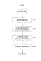
- FIG. 3 is a flowchart of a method of detecting an uneven road surface according to an embodiment of the present invention.
- a disparity map is input so as to calculate the direction of a road surface (S101), and a projection of the cross sectional surface of the road surface is calculated (S102) so as to obtain the projection of the road surface in the real world.
- the projection of the cross sectional surface of the road surface is fitted so as to obtain a road line of the cross sectional surface (S103).
- the road surface is extracted (S104).
- the step of calculating the direction of the road surface (S101) is performed in the road surface direction detector 103.
- the step of calculating the projection of the cross sectional surface of the road surface (S102) is performed in the cross sectional surface projection calculator 104.
- the step of fitting the projection of the cross sectional surface of the road surface (S103) is performed in the cross sectional surface processor 105.
- the step of extracting the road surface (S104) is performed in the road surface extractor 106.
- FIG. 4 illustrates a hardware system
- an input device 1100 is configured to input the disparity map of each frame.
- a CPU 1200 is configured to accomplish road surface detection.
- the input data and the intermediate results are stored in a storage device 1300.
- an output device 1400 outputs a final road surface.
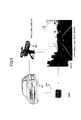
- FIG. 5 illustrates an example adopting a method of detecting a road surface according to an embodiment of the present invention.
- FIG. 5 there is a vehicle 201 in which a two-lens camera 202 is installed.
- the two-lens camera 202 captures a left lens based image and a right lens based image (203).
- a chip 204 processes the images so as to extract an object.
- FIG. 6 illustrated a sequence of a signal process adopting a method of detecting a road surface according to an embodiment of the present invention.
- an input device inputs a disparity map (S42) into a road surface detection system (S43).
- a road surface direction detector (S44) obtains the direction of a road surface, and by using cross sectional surface projection calculator (S45), the projection of the cross sectional surface of the road surface in the real world is calculated; then division of the cross sectional surface of the road surface is accomplished.
- Cross sectional surface processor (S46) fits the division of the cross sectional surface of the road surface.
- a road surface extractor (S47) extracts the road surface on the basis of the direction of the road surface and the fit of the cross sectional surface of the road (S48). Finally the road surface (S48) is output to an output device (S49).
- FIGS. 7 to 11 illustrate a specific example of an embodiment of the present invention.
- FIG. 7 illustrates a relationship between road surface direction expressions in the real world and in a V-disparity map.
- a road surface is detected from a disparity map generated on the basis of a left image and a right image captured by a two-lens camera.
- the direction of the road surface is calculated so as to obtain a direction of the road surface in the real world (S101) in FIG. 3 .
- the road surface direction expression in the real world and the road surface direction expression in a V-disparity map are the same line.
- a V-disparity map of a scene is calculated.
- FIG. 8 illustrates the calculated V-disparity map.
- FIG. 8 illustrates the calculated V-disparity map.
- FIG. 9 illustrates a process of obtaining a fitted road line by carrying out fitting.
- a road line in the V-disparity map is obtained.
- the lowest point in the V-disparity map is selected, and at least one line is obtained by using the Hough transform. Then an obtained line on which the number of points is maximum is selected.
- kr refers to the direction of the road surface in the real world.
- a road line in a disparity map, corresponding to a horizontal road is L horizonal :
- v k horizaonal *d+b horizonal .
- f refers to a camera focal length.
- FIG. 10 illustrates a process of converting a point in a disparity map coordinate system into a point in the real world coordinate system.
- a projection of cross sectional surface of a road surface is calculated as shown in FIG. 10 .
- the coordinates in the real world of a point in a disparity map is calculated.
- FIG. 11 illustrates a process of obtaining cross sectional surface of a road surface in the real world coordinate system. As shown in FIG. 11 , projection is carried out in the real world coordinate system. By carrying out this kind of projection in the real world coordinate system, it is possible to avoid the overlapping of a road white line and an object.
- the process is as follows.
- x ⁇ u - u vp * BASE / d
- y ⁇ v k v * d - d v * BASE / d
- BASE refers to a distance between two cameras
- d refers to a disparity value
- x' and y' refer to real distances to the disappearance point vp.
- z0 is a predetermined value.
- the projection along the direction of the road surface may guarantee that the relative position of the road surface and an object thereon remain unchanged.
- the cross sectional surface of the road surface is divided so as to obtain regions of the road surface.
- the road surface regions are obtained on the basis of height and width. The reason is that the height of a road is lower than that of an obstacle, and the width of the road is different from that of an obstacle (for example, a car or a person) in general.
- cross sectional surface line of the road surface is fitted in each road surface region.
- the above described method may be executed in a computer (a processor), or may be distributedly executed by plural computers.
- a program which may cause a computer to carry out the above method may be transferred to a remote computer in which the program will be executed.
Landscapes
- Engineering & Computer Science (AREA)
- Computer Vision & Pattern Recognition (AREA)
- Physics & Mathematics (AREA)
- General Physics & Mathematics (AREA)
- Theoretical Computer Science (AREA)
- Image Processing (AREA)
- Image Analysis (AREA)
- Traffic Control Systems (AREA)
- Length Measuring Devices By Optical Means (AREA)
Applications Claiming Priority (1)
| Application Number | Priority Date | Filing Date | Title |
|---|---|---|---|
| CN201210335758.1A CN103679120B (zh) | 2012-09-11 | 2012-09-11 | 不平道路的检测方法和系统 |
Publications (2)
| Publication Number | Publication Date |
|---|---|
| EP2720193A2 true EP2720193A2 (fr) | 2014-04-16 |
| EP2720193A3 EP2720193A3 (fr) | 2017-12-13 |
Family
ID=49083519
Family Applications (1)
| Application Number | Title | Priority Date | Filing Date |
|---|---|---|---|
| EP13181638.1A Ceased EP2720193A3 (fr) | 2012-09-11 | 2013-08-26 | Procédé et système pour détecter des irrégularités de la surface de la route |
Country Status (2)
| Country | Link |
|---|---|
| EP (1) | EP2720193A3 (fr) |
| CN (1) | CN103679120B (fr) |
Cited By (2)
| Publication number | Priority date | Publication date | Assignee | Title |
|---|---|---|---|---|
| CN111709938A (zh) * | 2020-06-18 | 2020-09-25 | 武汉唯理科技有限公司 | 一种基于深度图的路面缺陷及抛洒物检测方法 |
| CN118840495A (zh) * | 2024-06-24 | 2024-10-25 | 元橡科技(苏州)有限公司 | 一种车轮轨迹高程提取方法、系统以及电子设备 |
Families Citing this family (12)
| Publication number | Priority date | Publication date | Assignee | Title |
|---|---|---|---|---|
| CN104156969B (zh) * | 2014-08-21 | 2017-02-01 | 重庆数字城市科技有限公司 | 基于全景影像景深图的探面方法 |
| JP6160634B2 (ja) * | 2015-02-09 | 2017-07-12 | トヨタ自動車株式会社 | 走行路面検出装置及び走行路面検出方法 |
| JP6156400B2 (ja) * | 2015-02-09 | 2017-07-05 | トヨタ自動車株式会社 | 走行路面検出装置及び走行路面検出方法 |
| JP6406289B2 (ja) * | 2016-03-14 | 2018-10-17 | オムロン株式会社 | 路面形状測定装置、測定方法、及び、プログラム |
| US10372128B2 (en) * | 2016-11-21 | 2019-08-06 | Ford Global Technologies, Llc | Sinkhole detection systems and methods |
| TWI658431B (zh) * | 2017-10-02 | 2019-05-01 | 緯創資通股份有限公司 | 影像處理方法、影像處理裝置及電腦可讀取記錄媒體 |
| CN108009511A (zh) * | 2017-12-14 | 2018-05-08 | 元橡科技(北京)有限公司 | 基于rgbd的可行使区域检测方法和装置 |
| CN107977654B (zh) * | 2017-12-25 | 2020-07-31 | 海信集团有限公司 | 一种道路区域检测方法、装置及终端 |
| CN110222557B (zh) * | 2019-04-22 | 2021-09-21 | 北京旷视科技有限公司 | 路况的实时检测方法、装置、系统和存储介质 |
| CN112304293B (zh) * | 2019-08-02 | 2022-09-13 | 北京地平线机器人技术研发有限公司 | 道路高度检测方法、装置、可读存储介质和电子设备 |
| CN114495062B (zh) * | 2022-01-26 | 2025-09-30 | 无锡学院 | 一种前方路面平整度检测方法 |
| CN116189133B (zh) * | 2023-04-26 | 2023-07-28 | 宜宾闪马智通科技有限公司 | 道路巡检判定方法及装置 |
Citations (1)
| Publication number | Priority date | Publication date | Assignee | Title |
|---|---|---|---|---|
| US8108119B2 (en) | 2006-04-21 | 2012-01-31 | Sri International | Apparatus and method for object detection and tracking and roadway awareness using stereo cameras |
Family Cites Families (3)
| Publication number | Priority date | Publication date | Assignee | Title |
|---|---|---|---|---|
| CN101303732B (zh) * | 2008-04-11 | 2011-06-22 | 西安交通大学 | 基于车载单目相机的运动目标感知与告警方法 |
| EP2246806B1 (fr) * | 2009-04-29 | 2014-04-02 | Autoliv Development AB | Procédé de vision et système de détection automatique d'objets en face d'un véhicule à moteur |
| US8744131B2 (en) * | 2009-09-29 | 2014-06-03 | Panasonic Corporation | Pedestrian-crossing marking detecting method and pedestrian-crossing marking detecting device |
-
2012
- 2012-09-11 CN CN201210335758.1A patent/CN103679120B/zh active Active
-
2013
- 2013-08-26 EP EP13181638.1A patent/EP2720193A3/fr not_active Ceased
Patent Citations (1)
| Publication number | Priority date | Publication date | Assignee | Title |
|---|---|---|---|---|
| US8108119B2 (en) | 2006-04-21 | 2012-01-31 | Sri International | Apparatus and method for object detection and tracking and roadway awareness using stereo cameras |
Non-Patent Citations (1)
| Title |
|---|
| Z.HU, F. LAMOSA; K. UCHIMURA: "A Complete U-V-Disparity Study for Stereovision Based 3d Driving Environment Analysis", PROCEEDINGS OF THE FIFTH INTERNATIONAL CONFERENCE ON 3- D DIGITAL IMAGING AND MODELING (3DIM05, 2005, pages 204 - 211 |
Cited By (3)
| Publication number | Priority date | Publication date | Assignee | Title |
|---|---|---|---|---|
| CN111709938A (zh) * | 2020-06-18 | 2020-09-25 | 武汉唯理科技有限公司 | 一种基于深度图的路面缺陷及抛洒物检测方法 |
| CN111709938B (zh) * | 2020-06-18 | 2023-07-07 | 武汉唯理科技有限公司 | 一种基于深度图的路面缺陷及抛洒物检测方法 |
| CN118840495A (zh) * | 2024-06-24 | 2024-10-25 | 元橡科技(苏州)有限公司 | 一种车轮轨迹高程提取方法、系统以及电子设备 |
Also Published As
| Publication number | Publication date |
|---|---|
| CN103679120A (zh) | 2014-03-26 |
| CN103679120B (zh) | 2016-12-28 |
| EP2720193A3 (fr) | 2017-12-13 |
Similar Documents
| Publication | Publication Date | Title |
|---|---|---|
| EP2720193A2 (fr) | Procédé et système pour détecter des irrégularités de la surface de la route | |
| US8861791B2 (en) | Method and device for detecting road region as well as method and device for detecting road line | |
| EP2728546B1 (fr) | Procédé et système pour détecter un objet sur une route | |
| US11670087B2 (en) | Training data generating method for image processing, image processing method, and devices thereof | |
| JP6587000B2 (ja) | 画像処理装置、撮像装置、移動体機器制御システム、画像処理方法、及びプログラム | |
| US10580155B2 (en) | Image processing apparatus, imaging device, device control system, frequency distribution image generation method, and recording medium | |
| EP2779025B1 (fr) | Procédé et système de détection de bord de route | |
| RU2636120C2 (ru) | Устройство обнаружения трехмерных объектов | |
| CN103731652B (zh) | 移动面分界线认知装置和方法、以及移动体设备控制系统 | |
| EP2476996B1 (fr) | Procédé de calcul de parallaxe et dispositif de calcul de parallaxe | |
| EP3545464B1 (fr) | Dispositif de traitement d'informations, dispositif d'imagerie, système de commande d'équipement, objet mobile, procédé de traitement d'informations et support d'enregistrement lisible par ordinateur | |
| WO2017090326A1 (fr) | Dispositif de traitement d'images, dispositif de capture d'images, système de commande d'appareil, procédé de génération de données de distribution, et programme | |
| EP3422289A1 (fr) | Dispositif de traitement d'images, dispositif d'imagerie, système de commande d'appareil d'entité mobile, procédé de traitement d'image et programme | |
| KR101285106B1 (ko) | 영상 데이터 융합 기반의 장애물체 검출 방법 및 장치 | |
| KR20160123668A (ko) | 무인자동주차 기능 지원을 위한 장애물 및 주차구획 인식 장치 및 그 방법 | |
| EP3282389B1 (fr) | Appareil de traitement d'image, appareil de capture d'image, système de commande d'appareil de corps mobile, procédé de traitement d'image, et programme | |
| EP3324359B1 (fr) | Dispositif de traitement d'images et procédé de traitement d'images | |
| JP6583527B2 (ja) | 画像処理装置、撮像装置、移動体機器制御システム、画像処理方法、及びプログラム | |
| WO2017138245A1 (fr) | Dispositif de traitement d'images, dispositif de reconnaissance d'objet, système de commande de dispositifs, et procédé et programme de traitement d'images | |
| CN110341621B (zh) | 一种障碍物检测方法及装置 | |
| KR101366871B1 (ko) | 관심영역 분할을 통한 곡선차선 검출장치 및 그 방법 | |
| JPWO2017145634A1 (ja) | 画像処理装置、撮像装置、移動体機器制御システム、画像処理方法、及びプログラム | |
| KR20180063524A (ko) | 가상 차선을 이용한 전방 차량 위험도 감지 방법 및 장치 | |
| KR20190134303A (ko) | 영상 인식 장치 및 그 방법 | |
| CN103577790B (zh) | 道路转弯类型检测方法和装置 |
Legal Events
| Date | Code | Title | Description |
|---|---|---|---|
| PUAI | Public reference made under article 153(3) epc to a published international application that has entered the european phase |
Free format text: ORIGINAL CODE: 0009012 |
|
| 17P | Request for examination filed |
Effective date: 20130826 |
|
| AK | Designated contracting states |
Kind code of ref document: A2 Designated state(s): AL AT BE BG CH CY CZ DE DK EE ES FI FR GB GR HR HU IE IS IT LI LT LU LV MC MK MT NL NO PL PT RO RS SE SI SK SM TR |
|
| AX | Request for extension of the european patent |
Extension state: BA ME |
|
| PUAL | Search report despatched |
Free format text: ORIGINAL CODE: 0009013 |
|
| AK | Designated contracting states |
Kind code of ref document: A3 Designated state(s): AL AT BE BG CH CY CZ DE DK EE ES FI FR GB GR HR HU IE IS IT LI LT LU LV MC MK MT NL NO PL PT RO RS SE SI SK SM TR |
|
| AX | Request for extension of the european patent |
Extension state: BA ME |
|
| RIC1 | Information provided on ipc code assigned before grant |
Ipc: G06T 7/20 20170101ALI20171106BHEP Ipc: G06T 7/00 20170101AFI20171106BHEP Ipc: G08G 1/00 20060101ALI20171106BHEP |
|
| 17Q | First examination report despatched |
Effective date: 20190213 |
|
| STAA | Information on the status of an ep patent application or granted ep patent |
Free format text: STATUS: THE APPLICATION HAS BEEN REFUSED |
|
| 18R | Application refused |
Effective date: 20200312 |