EP2720301A2 - Batteriemodul mit erhöhter verbindungszuverlässigkeit und mittelgrosses oder grosses batteriepack damit - Google Patents
Batteriemodul mit erhöhter verbindungszuverlässigkeit und mittelgrosses oder grosses batteriepack damit Download PDFInfo
- Publication number
- EP2720301A2 EP2720301A2 EP12812024.3A EP12812024A EP2720301A2 EP 2720301 A2 EP2720301 A2 EP 2720301A2 EP 12812024 A EP12812024 A EP 12812024A EP 2720301 A2 EP2720301 A2 EP 2720301A2
- Authority
- EP
- European Patent Office
- Prior art keywords
- electrically connected
- electrical connection
- battery
- battery module
- unit modules
- Prior art date
- Legal status (The legal status is an assumption and is not a legal conclusion. Google has not performed a legal analysis and makes no representation as to the accuracy of the status listed.)
- Granted
Links
Images



Classifications
-
- B—PERFORMING OPERATIONS; TRANSPORTING
- B60—VEHICLES IN GENERAL
- B60L—PROPULSION OF ELECTRICALLY-PROPELLED VEHICLES; SUPPLYING ELECTRIC POWER FOR AUXILIARY EQUIPMENT OF ELECTRICALLY-PROPELLED VEHICLES; ELECTRODYNAMIC BRAKE SYSTEMS FOR VEHICLES IN GENERAL; MAGNETIC SUSPENSION OR LEVITATION FOR VEHICLES; MONITORING OPERATING VARIABLES OF ELECTRICALLY-PROPELLED VEHICLES; ELECTRIC SAFETY DEVICES FOR ELECTRICALLY-PROPELLED VEHICLES
- B60L50/00—Electric propulsion with power supplied within the vehicle
- B60L50/50—Electric propulsion with power supplied within the vehicle using propulsion power supplied by batteries or fuel cells
- B60L50/60—Electric propulsion with power supplied within the vehicle using propulsion power supplied by batteries or fuel cells using power supplied by batteries
- B60L50/64—Constructional details of batteries specially adapted for electric vehicles
-
- H—ELECTRICITY
- H01—ELECTRIC ELEMENTS
- H01M—PROCESSES OR MEANS, e.g. BATTERIES, FOR THE DIRECT CONVERSION OF CHEMICAL ENERGY INTO ELECTRICAL ENERGY
- H01M50/00—Constructional details or processes of manufacture of the non-active parts of electrochemical cells other than fuel cells, e.g. hybrid cells
- H01M50/20—Mountings; Secondary casings or frames; Racks, modules or packs; Suspension devices; Shock absorbers; Transport or carrying devices; Holders
-
- H—ELECTRICITY
- H01—ELECTRIC ELEMENTS
- H01M—PROCESSES OR MEANS, e.g. BATTERIES, FOR THE DIRECT CONVERSION OF CHEMICAL ENERGY INTO ELECTRICAL ENERGY
- H01M50/00—Constructional details or processes of manufacture of the non-active parts of electrochemical cells other than fuel cells, e.g. hybrid cells
- H01M50/50—Current conducting connections for cells or batteries
- H01M50/528—Fixed electrical connections, i.e. not intended for disconnection
-
- B—PERFORMING OPERATIONS; TRANSPORTING
- B60—VEHICLES IN GENERAL
- B60L—PROPULSION OF ELECTRICALLY-PROPELLED VEHICLES; SUPPLYING ELECTRIC POWER FOR AUXILIARY EQUIPMENT OF ELECTRICALLY-PROPELLED VEHICLES; ELECTRODYNAMIC BRAKE SYSTEMS FOR VEHICLES IN GENERAL; MAGNETIC SUSPENSION OR LEVITATION FOR VEHICLES; MONITORING OPERATING VARIABLES OF ELECTRICALLY-PROPELLED VEHICLES; ELECTRIC SAFETY DEVICES FOR ELECTRICALLY-PROPELLED VEHICLES
- B60L58/00—Methods or circuit arrangements for monitoring or controlling batteries or fuel cells, specially adapted for electric vehicles
- B60L58/10—Methods or circuit arrangements for monitoring or controlling batteries or fuel cells, specially adapted for electric vehicles for monitoring or controlling batteries
- B60L58/18—Methods or circuit arrangements for monitoring or controlling batteries or fuel cells, specially adapted for electric vehicles for monitoring or controlling batteries of two or more battery modules
- B60L58/21—Methods or circuit arrangements for monitoring or controlling batteries or fuel cells, specially adapted for electric vehicles for monitoring or controlling batteries of two or more battery modules having the same nominal voltage
-
- H—ELECTRICITY
- H01—ELECTRIC ELEMENTS
- H01M—PROCESSES OR MEANS, e.g. BATTERIES, FOR THE DIRECT CONVERSION OF CHEMICAL ENERGY INTO ELECTRICAL ENERGY
- H01M50/00—Constructional details or processes of manufacture of the non-active parts of electrochemical cells other than fuel cells, e.g. hybrid cells
- H01M50/20—Mountings; Secondary casings or frames; Racks, modules or packs; Suspension devices; Shock absorbers; Transport or carrying devices; Holders
- H01M50/204—Racks, modules or packs for multiple batteries or multiple cells
- H01M50/207—Racks, modules or packs for multiple batteries or multiple cells characterised by their shape
- H01M50/209—Racks, modules or packs for multiple batteries or multiple cells characterised by their shape adapted for prismatic or rectangular cells
-
- H—ELECTRICITY
- H01—ELECTRIC ELEMENTS
- H01M—PROCESSES OR MEANS, e.g. BATTERIES, FOR THE DIRECT CONVERSION OF CHEMICAL ENERGY INTO ELECTRICAL ENERGY
- H01M50/00—Constructional details or processes of manufacture of the non-active parts of electrochemical cells other than fuel cells, e.g. hybrid cells
- H01M50/20—Mountings; Secondary casings or frames; Racks, modules or packs; Suspension devices; Shock absorbers; Transport or carrying devices; Holders
- H01M50/204—Racks, modules or packs for multiple batteries or multiple cells
- H01M50/207—Racks, modules or packs for multiple batteries or multiple cells characterised by their shape
- H01M50/211—Racks, modules or packs for multiple batteries or multiple cells characterised by their shape adapted for pouch cells
-
- H—ELECTRICITY
- H01—ELECTRIC ELEMENTS
- H01M—PROCESSES OR MEANS, e.g. BATTERIES, FOR THE DIRECT CONVERSION OF CHEMICAL ENERGY INTO ELECTRICAL ENERGY
- H01M50/00—Constructional details or processes of manufacture of the non-active parts of electrochemical cells other than fuel cells, e.g. hybrid cells
- H01M50/20—Mountings; Secondary casings or frames; Racks, modules or packs; Suspension devices; Shock absorbers; Transport or carrying devices; Holders
- H01M50/249—Mountings; Secondary casings or frames; Racks, modules or packs; Suspension devices; Shock absorbers; Transport or carrying devices; Holders specially adapted for aircraft or vehicles, e.g. cars or trains
-
- H—ELECTRICITY
- H01—ELECTRIC ELEMENTS
- H01M—PROCESSES OR MEANS, e.g. BATTERIES, FOR THE DIRECT CONVERSION OF CHEMICAL ENERGY INTO ELECTRICAL ENERGY
- H01M50/00—Constructional details or processes of manufacture of the non-active parts of electrochemical cells other than fuel cells, e.g. hybrid cells
- H01M50/50—Current conducting connections for cells or batteries
- H01M50/502—Interconnectors for connecting terminals of adjacent batteries; Interconnectors for connecting cells outside a battery casing
- H01M50/505—Interconnectors for connecting terminals of adjacent batteries; Interconnectors for connecting cells outside a battery casing comprising a single busbar
-
- H—ELECTRICITY
- H01—ELECTRIC ELEMENTS
- H01M—PROCESSES OR MEANS, e.g. BATTERIES, FOR THE DIRECT CONVERSION OF CHEMICAL ENERGY INTO ELECTRICAL ENERGY
- H01M50/00—Constructional details or processes of manufacture of the non-active parts of electrochemical cells other than fuel cells, e.g. hybrid cells
- H01M50/50—Current conducting connections for cells or batteries
- H01M50/502—Interconnectors for connecting terminals of adjacent batteries; Interconnectors for connecting cells outside a battery casing
- H01M50/509—Interconnectors for connecting terminals of adjacent batteries; Interconnectors for connecting cells outside a battery casing characterised by the type of connection, e.g. mixed connections
-
- H—ELECTRICITY
- H01—ELECTRIC ELEMENTS
- H01M—PROCESSES OR MEANS, e.g. BATTERIES, FOR THE DIRECT CONVERSION OF CHEMICAL ENERGY INTO ELECTRICAL ENERGY
- H01M50/00—Constructional details or processes of manufacture of the non-active parts of electrochemical cells other than fuel cells, e.g. hybrid cells
- H01M50/50—Current conducting connections for cells or batteries
- H01M50/502—Interconnectors for connecting terminals of adjacent batteries; Interconnectors for connecting cells outside a battery casing
- H01M50/509—Interconnectors for connecting terminals of adjacent batteries; Interconnectors for connecting cells outside a battery casing characterised by the type of connection, e.g. mixed connections
- H01M50/51—Connection only in series
-
- H—ELECTRICITY
- H01—ELECTRIC ELEMENTS
- H01M—PROCESSES OR MEANS, e.g. BATTERIES, FOR THE DIRECT CONVERSION OF CHEMICAL ENERGY INTO ELECTRICAL ENERGY
- H01M50/00—Constructional details or processes of manufacture of the non-active parts of electrochemical cells other than fuel cells, e.g. hybrid cells
- H01M50/50—Current conducting connections for cells or batteries
- H01M50/502—Interconnectors for connecting terminals of adjacent batteries; Interconnectors for connecting cells outside a battery casing
- H01M50/509—Interconnectors for connecting terminals of adjacent batteries; Interconnectors for connecting cells outside a battery casing characterised by the type of connection, e.g. mixed connections
- H01M50/512—Connection only in parallel
-
- H—ELECTRICITY
- H01—ELECTRIC ELEMENTS
- H01M—PROCESSES OR MEANS, e.g. BATTERIES, FOR THE DIRECT CONVERSION OF CHEMICAL ENERGY INTO ELECTRICAL ENERGY
- H01M50/00—Constructional details or processes of manufacture of the non-active parts of electrochemical cells other than fuel cells, e.g. hybrid cells
- H01M50/50—Current conducting connections for cells or batteries
- H01M50/502—Interconnectors for connecting terminals of adjacent batteries; Interconnectors for connecting cells outside a battery casing
- H01M50/514—Methods for interconnecting adjacent batteries or cells
- H01M50/516—Methods for interconnecting adjacent batteries or cells by welding, soldering or brazing
-
- H—ELECTRICITY
- H01—ELECTRIC ELEMENTS
- H01M—PROCESSES OR MEANS, e.g. BATTERIES, FOR THE DIRECT CONVERSION OF CHEMICAL ENERGY INTO ELECTRICAL ENERGY
- H01M50/00—Constructional details or processes of manufacture of the non-active parts of electrochemical cells other than fuel cells, e.g. hybrid cells
- H01M50/50—Current conducting connections for cells or batteries
- H01M50/502—Interconnectors for connecting terminals of adjacent batteries; Interconnectors for connecting cells outside a battery casing
- H01M50/514—Methods for interconnecting adjacent batteries or cells
- H01M50/517—Methods for interconnecting adjacent batteries or cells by fixing means, e.g. screws, rivets or bolts
-
- B—PERFORMING OPERATIONS; TRANSPORTING
- B60—VEHICLES IN GENERAL
- B60L—PROPULSION OF ELECTRICALLY-PROPELLED VEHICLES; SUPPLYING ELECTRIC POWER FOR AUXILIARY EQUIPMENT OF ELECTRICALLY-PROPELLED VEHICLES; ELECTRODYNAMIC BRAKE SYSTEMS FOR VEHICLES IN GENERAL; MAGNETIC SUSPENSION OR LEVITATION FOR VEHICLES; MONITORING OPERATING VARIABLES OF ELECTRICALLY-PROPELLED VEHICLES; ELECTRIC SAFETY DEVICES FOR ELECTRICALLY-PROPELLED VEHICLES
- B60L2240/00—Control parameters of input or output; Target parameters
- B60L2240/40—Drive Train control parameters
- B60L2240/54—Drive Train control parameters related to batteries
- B60L2240/547—Voltage
-
- Y—GENERAL TAGGING OF NEW TECHNOLOGICAL DEVELOPMENTS; GENERAL TAGGING OF CROSS-SECTIONAL TECHNOLOGIES SPANNING OVER SEVERAL SECTIONS OF THE IPC; TECHNICAL SUBJECTS COVERED BY FORMER USPC CROSS-REFERENCE ART COLLECTIONS [XRACs] AND DIGESTS
- Y02—TECHNOLOGIES OR APPLICATIONS FOR MITIGATION OR ADAPTATION AGAINST CLIMATE CHANGE
- Y02E—REDUCTION OF GREENHOUSE GAS [GHG] EMISSIONS, RELATED TO ENERGY GENERATION, TRANSMISSION OR DISTRIBUTION
- Y02E60/00—Enabling technologies; Technologies with a potential or indirect contribution to GHG emissions mitigation
- Y02E60/10—Energy storage using batteries
-
- Y—GENERAL TAGGING OF NEW TECHNOLOGICAL DEVELOPMENTS; GENERAL TAGGING OF CROSS-SECTIONAL TECHNOLOGIES SPANNING OVER SEVERAL SECTIONS OF THE IPC; TECHNICAL SUBJECTS COVERED BY FORMER USPC CROSS-REFERENCE ART COLLECTIONS [XRACs] AND DIGESTS
- Y02—TECHNOLOGIES OR APPLICATIONS FOR MITIGATION OR ADAPTATION AGAINST CLIMATE CHANGE
- Y02T—CLIMATE CHANGE MITIGATION TECHNOLOGIES RELATED TO TRANSPORTATION
- Y02T10/00—Road transport of goods or passengers
- Y02T10/60—Other road transportation technologies with climate change mitigation effect
- Y02T10/70—Energy storage systems for electromobility, e.g. batteries
-
- Y—GENERAL TAGGING OF NEW TECHNOLOGICAL DEVELOPMENTS; GENERAL TAGGING OF CROSS-SECTIONAL TECHNOLOGIES SPANNING OVER SEVERAL SECTIONS OF THE IPC; TECHNICAL SUBJECTS COVERED BY FORMER USPC CROSS-REFERENCE ART COLLECTIONS [XRACs] AND DIGESTS
- Y10—TECHNICAL SUBJECTS COVERED BY FORMER USPC
- Y10T—TECHNICAL SUBJECTS COVERED BY FORMER US CLASSIFICATION
- Y10T29/00—Metal working
- Y10T29/49—Method of mechanical manufacture
- Y10T29/49002—Electrical device making
- Y10T29/49108—Electric battery cell making
Definitions
- the present invention relates to a battery module of improved connection reliability and a middle or large-sized battery pack including the same and, more particularly, to a battery module including a plurality of unit modules, based on battery cells which can be charged and discharged, electrically connected to each other, wherein the unit modules are electrically connected to each other in series and/or in parallel or the unit modules are electrically connected to a bus bar in series and/or in parallel, the battery module has two or more electrical connection points, and the number of electrically connected members at each of the electrical connection points is less than the total number of the electrically connected members of the battery module.
- a secondary battery which can be charged and discharged, has been widely used as an energy source for wireless mobile devices.
- the secondary battery has attracted considerable attention as a power source for devices which require high output and large capacity, such as electric vehicles (EV), hybrid electric vehicles (HEV), and plug-in hybrid electric vehicles (Plug-in HEV), which have been developed to solve problems, such as air pollution, caused by existing gasoline and diesel vehicles using fossil fuels.
- EV electric vehicles
- HEV hybrid electric vehicles
- Plug-in HEV plug-in hybrid electric vehicles
- Such devices use a middle or large-sized battery module having a plurality of battery cells electrically connected to each other to provide high output and large capacity.
- the middle or large-sized battery module is manufactured so as to have as small a size and weight as possible.
- a prismatic battery or a pouch-shaped battery which can be stacked with high integration and has a small weight to capacity ratio, is usually used as a battery cell (unit battery) of the middle or large-sized battery module.
- much interest is currently focused on the pouch-shaped battery, which uses an aluminum laminate sheet as a sheathing member, because the pouch-shaped battery is lightweight, the manufacturing cost of the pouch-shaped battery is low, and it is easy to modify the shape of the pouch-shaped battery.
- a battery module mounted in a middle or large-sized battery pack is generally manufactured by stacking a plurality of battery cells with high integration in a state in which electrode terminals of adjacent ones of the battery cells are electrically connected to each other.
- FIG. 1 is a perspective view typically showing an electrical connection structure of a conventional representative battery module.
- a battery module 50 is configured to have a structure in which electrode terminals 25 of three battery cells 20 are electrically connected to a bus bar 10 in a state in which the battery cells 20 are stacked.
- the three battery cells 20 are sequentially stacked and are then electrically connected to the bus bar 10, to which other battery cells are electrically connected.
- ultrasonic welding is generally used.
- ultrasonic waves may be transferred to other regions of the battery cells with the result that the battery cells may be electrically damaged, the lifespan of a welding device may be reduced, and the battery cells may be attached to the welding device.
- a battery module including a plurality of unit modules, based on battery cells which can be charged and discharged, electrically connected to each other, wherein the unit modules are electrically connected to each other in series and/or in parallel or the unit modules are electrically connected to a bus bar in series and/or in parallel, the battery module has two or more electrical connection points, and the number of electrically connected members at each of the electrical connection points is less than the total number of the electrically connected members of the battery module.
- electrode terminals of unit modules are simultaneously connected to each other by welding or the electrode terminals of unit modules are simultaneously connected to a bus bar by welding in a state in which the unit modules are stacked.
- the same regions are simultaneously welded with the result that, as the number of electrically connected members is increased, the welded regions may be inevitably damaged as previously described.
- the battery module according to the present invention is configured such that two or more electrical connection points are provided and the number of electrically connected members at each of the electrical connection points is less than the total number of the electrically connected members of the battery module.
- the amount of energy necessary at each position is reduced and, therefore, it is possible to reduce damage to insides and outsides of the battery cells and a welding device in addition to the electrical connection points.
- the number of the electrically connected members to be connected per position is reduced. Consequently, it is possible to use various connection methods, which is very preferable.
- connection point' used in this specification is defined as one electrical connection point in a case in which two or more welding points are formed to strengthen coupling or connection between the same electrically connected members.
- each of the unit modules may include one battery cell or a plurality of battery cells.
- each of the unit modules may include one battery cell.
- one battery cell constitute one unit module and electrode terminals of the respective battery cells have different electrical connection points, electrical connection points of the electrically connected members do not overlap. Consequently, it is possible to perform welding only using a small amount of energy, thereby preventing other regions of the battery cells from being affected by welding.
- each of the unit modules may include a combination of two or more battery cells connected to each other via one electrical connection point.
- each of the unit modules may include two to four battery cells.
- the battery cells in each of the unit modules may be configured to have two or more electrical connection points in the same manner as in electrical connection between the unit modules.
- each of the battery cells may be a secondary battery having a small thickness and a relatively large width and length so as to minimize the overall size of a battery module when the battery cells are stacked to constitute the battery module.
- each of the battery cells is a plate-shaped battery cell configured to have an easily stackable structure.
- the plate-shaped battery cell may be (a) a pouch-shaped battery cell configured to have a structure in which an electrode assembly of a cathode/separator/anode structure is mounted in a battery case formed of a laminate sheet comprising a resin layer and a metal layer and a cathode terminal and an anode terminal protrude from one side or opposite sides of the battery case or (b) a prismatic battery cell configured to have a structure in which an electrode assembly of a cathode/separator/anode structure is mounted in a prismatic battery case formed of a metal or plastic material and a cathode terminal and an anode terminal protrude from one side or opposite sides of the battery case.
- the unit modules may be electrically connected to the bus bar in a state in which electrode terminals of the unit modules are electrically connected to each other and two or more electrical connection points may be provided between the unit modules and between the unit modules and the bus bar.
- the number of the electrical connection points may be 2 to n.
- the number of the electrically connected members at the electrical connection points may be 4 or less. More preferably, the number of the electrically connected members at the electrical connection points is 2.
- each of the electrically connected members may be welded only using a small amount of energy.
- the number of the electrical connection points may be n.
- the number of the electrically connected members at each of the electrical connection points may be 2 and adjacent ones of the electrical connection points may deviate from each other.
- the electrical connection points sequentially deviate from each other. Even in a case in which the electrically connected members are stacked, therefore, easy connection is achieved.
- that the electrical connection points deviate from each other means that the electrical connection points do not overlap.
- that the electrical connection points sequentially deviate from each other means that the electrical connection points are gradually distributed in one direction such that the electrical connection points do not overlap at the respective positions thereof.
- the electrically connected members are sequentially electrically connected to each other in a state in which the electrical connection points of the electrically connected members do not overlap based on a desired structure, thereby improving manufacturing efficiency of the battery module.
- each of the electrode terminals may have a thickness of 50 to 1000 ⁇ m and each of the electrode terminals has a width of 1 to 20 cm.
- embodiments of the present invention are not limited thereto according to the specification of the battery cells. That is, even electrode terminals having larger thicknesses and widths than conventional electrode terminals may be electrically connected to each other. The same may be equally applied to the bus bar.
- the electrically connected members at the electrical connection points may be coupled to each other by one or more selected from a group consisting of bolting, riveting, crimping, soldering, laser welding, ultrasonic welding, and resistance welding.
- the electrically connected members may be coupled to each other using various methods unlike a conventional structure in which the number of stacked battery cells is increased, thicknesses and widths of the electrode terminals and the bus bar are increased with the result that only ultrasonic welding is used to achieve coupling therebetween.
- a battery module including a plurality of unit modules, based on battery cells which can be charged and discharged, electrically connected to each other, wherein the unit modules are electrically connected to each other in series and/or in parallel or the unit modules are electrically connected to a bus bar in series and/or in parallel, the battery module has two or more electrical connection points, a first electrically connected member and a second electrically connected member facing each other are electrically connected to each other via a first electrical connection point, and a third electrically connected member facing the first electrically connected member or the second electrically connected member is electrically connected to the first electrically connected member or the second electrically connected member via a second electrical connection point.
- This battery module also provides the same effects as the above.
- a manufacturing method of a battery module configured to have a structure in which unit modules are electrically connected to a bus bar in a state in which the unit modules are sequentially stacked, the manufacturing method including, in a structure in which electrode terminals of n unit modules are electrically connected to one bus bar in a state in which the electrode terminals of the n unit modules are electrically connected to each other, (a) connecting an electrode terminal of an uppermost unit module (first unit module) of the stacked unit modules to an electrode terminal of a second unit module stacked adjacent to the first unit module to form a first electrical connection point, (b) connecting the electrode terminal of the second unit module to an electrode terminal of a third unit module stacked adjacent to the second unit module at a position deviating from the first electrical connection point to form a second electrical connection point, (c) repeatedly performing the step (b) to electrically interconnect electrode terminals of n unit modules such that an (n-1)-th electrical connection point is formed, and (d) connecting an electrode terminal of an electrode terminal of an uppermost unit module (
- a middle or large-sized battery pack is manufactured using a plurality of battery cells to provide high output and large capacity. It is necessary for battery modules constituting the battery pack to exhibit higher installation efficiency, structural stability, and heat dissipation efficiency in order to secure safety of the battery pack in a limited installation space.
- a middle or large-sized battery pack manufactured by combining battery modules based on desired output and capacity.
- a middle or large-sized battery system according to the present invention may be manufactured by combining battery packs based on desired output and capacity.
- the middle or large-sized battery system may be used as a power source for an electric vehicle, a hybrid electric vehicle, a plug-in hybrid electric vehicle, or a power storage device, which has a limited installation space and is exposed to frequent vibration and strong impact in consideration of installation efficiency and structural stability as described above.
- the battery module according to the present invention is configured such that two or more electrical connection points are provided and the number of electrically connected members at each of the electrical connection points is less than the total number of the electrically connected members of the battery module.
- the amount of energy necessary at each position is reduced and, therefore, it is possible to minimize damage to unit modules and to improve efficiency of the battery module using various connection methods.
- FIG. 2 is a perspective view showing an electrical connection structure of a battery module according to an embodiment of the present invention
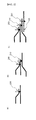
- FIG. 3 is a typical view showing a series of processes for connecting electrode terminals and a bus bar of FIG. 2 .
- a battery module 300 is configured to have a structure in which three battery cells 100 are electrically connected to a bus bar 120 in a state in which the battery cells 100 are sequentially stacked. Electrode terminals of the three pouch-shaped battery cells 100 are electrically connected to the bus bar 120 by welding in a state in which the electrode terminals of the three pouch-shaped battery cells 100 are electrically connected to one another.
- the number of electrical connection points is three.
- an electrode terminal 110 of the uppermost battery cell (first battery cell) 101 of the stacked battery cells 100 is connected to an electrode terminal 112 of a second battery cell 102 stacked adjacent to the first battery cell 101 to form a first electrical connection point 200.
- the electrode terminal 112 of the second battery cell 102 is connected to an electrode terminal 110 of a third battery cell 103 stacked adjacent to the second battery cell 102 to form a second electrical connection point 210.
- the electrode terminal 113 of the third battery cell 103 is connected to the bus bar 120 contacting the third battery cell 103 while being adjacent to the third battery cell 103 to form a third electrical connection point 220.
- FIG. 4 is a typical view showing an electrical connection structure of a battery module according to another embodiment of the present invention.
- the number of electrical connection points is six in a structure in which electrode terminals of six battery cells 100 and 100' are electrically connected to one bus bar 120 by welding in a state in which the electrode terminals of the six battery cells 100 and 100' are electrically connected to one another.
- FIG. 5 is a typical view showing an electrical connection structure of a battery module according to a further embodiment of the present invention.
- two unit modules 100A and 100B include three stacked battery cells 101a, 101b, and 101c and three stacked battery cells 102a, 102b, and 102c, respectively.
- Electrode terminals 111a, 111b, and 111c of the battery cells 101a, 101b, and 101c of the first unit module 100A are connected to an electrode terminal 112a of the uppermost battery cell 102a of the second unit module 100B to form a first electrical connection point 200a.
- the above electrode terminals are connected to the electrode terminals 112b and 112c of the other battery cells 101b and 101c of the second unit module 100B to form a second electrical connection point 210a and then the above electrode terminals are connected to a bus bar 120 contacting the electrode terminal 112c of the lowermost battery cell 102c of the second unit module 100B while being adjacent to the electrode terminal 112c of the lowermost battery cell 102c of the second unit module 100B to form a third electrical connection point 220a.
- the battery cells 101a, 101b, and 101c constituting the unit module 100A are electrically connected to one another via one electrical connection point as shown in FIG. 1 .
- Electrical connection of the unit module 100B is achieved in the same manner.
Landscapes
- Chemical & Material Sciences (AREA)
- Chemical Kinetics & Catalysis (AREA)
- Electrochemistry (AREA)
- General Chemical & Material Sciences (AREA)
- Engineering & Computer Science (AREA)
- Aviation & Aerospace Engineering (AREA)
- Sustainable Development (AREA)
- Sustainable Energy (AREA)
- Power Engineering (AREA)
- Transportation (AREA)
- Mechanical Engineering (AREA)
- Life Sciences & Earth Sciences (AREA)
- Battery Mounting, Suspending (AREA)
- Connection Of Batteries Or Terminals (AREA)
- Sealing Battery Cases Or Jackets (AREA)
Priority Applications (1)
| Application Number | Priority Date | Filing Date | Title |
|---|---|---|---|
| PL12812024T PL2720301T3 (pl) | 2011-07-13 | 2012-07-06 | Moduł baterii o zwiększonej niezawodności połączenia oraz zawierający go pakiet baterii o średnim i dużym rozmiarze |
Applications Claiming Priority (2)
| Application Number | Priority Date | Filing Date | Title |
|---|---|---|---|
| KR20110069555 | 2011-07-13 | ||
| PCT/KR2012/005366 WO2013009042A2 (ko) | 2011-07-13 | 2012-07-06 | 연결 신뢰성이 향상된 전지모듈 및 이를 포함하는 중대형 전지팩 |
Publications (3)
| Publication Number | Publication Date |
|---|---|
| EP2720301A2 true EP2720301A2 (de) | 2014-04-16 |
| EP2720301A4 EP2720301A4 (de) | 2015-07-15 |
| EP2720301B1 EP2720301B1 (de) | 2019-04-24 |
Family
ID=47506670
Family Applications (1)
| Application Number | Title | Priority Date | Filing Date |
|---|---|---|---|
| EP12812024.3A Active EP2720301B1 (de) | 2011-07-13 | 2012-07-06 | Batteriemodul mit erhöhter verbindungszuverlässigkeit und mittelgrosser oder grosser batteriepack damit |
Country Status (7)
| Country | Link |
|---|---|
| US (1) | US9865861B2 (de) |
| EP (1) | EP2720301B1 (de) |
| JP (1) | JP5932997B2 (de) |
| KR (1) | KR101361113B1 (de) |
| CN (1) | CN103650208B (de) |
| PL (1) | PL2720301T3 (de) |
| WO (1) | WO2013009042A2 (de) |
Cited By (4)
| Publication number | Priority date | Publication date | Assignee | Title |
|---|---|---|---|---|
| EP3109925A4 (de) * | 2014-03-31 | 2017-09-06 | LG Chem, Ltd. | Batteriemodul und batteriepack damit |
| WO2018220201A3 (en) * | 2017-06-01 | 2019-08-08 | Johnson Controls Advanced Power Solutions Gmbh | Cell assembly, cell sub-module, energy storage module and method for assembling the same |
| US11688900B2 (en) | 2017-06-01 | 2023-06-27 | Clarios Advanced Solutions Gmbh | Energy storage module cell assembly including pouch cell, compression element, thermal plate, and cell frame, and method for assembling the same |
| EP4362206A4 (de) * | 2022-07-08 | 2025-03-26 | Lg Energy Solution, Ltd. | Batteriemodul, batteriepack und fahrzeug damit |
Families Citing this family (27)
| Publication number | Priority date | Publication date | Assignee | Title |
|---|---|---|---|---|
| KR101747397B1 (ko) | 2013-09-25 | 2017-06-14 | 주식회사 엘지화학 | 댐핑 구조가 형성되어 있는 전극리드를 포함하는 전지모듈 |
| WO2015152527A1 (ko) * | 2014-03-31 | 2015-10-08 | 주식회사 엘지화학 | 배터리 모듈 및 이를 포함하는 배터리 팩 |
| JP6202210B2 (ja) * | 2014-08-06 | 2017-10-04 | 日産自動車株式会社 | 組電池およびタブ接合方法 |
| DE102015204724A1 (de) * | 2015-03-16 | 2016-09-22 | Volkswagen Aktiengesellschaft | Fortbewegungsmittel und Anordnung zur Anbindung eines elektrochemischen Energiespeichers an ein Bordnetz eines elektrisch antreibbaren Fortbewegungsmittels |
| KR101980501B1 (ko) | 2015-10-22 | 2019-05-20 | 닛산 지도우샤 가부시키가이샤 | 조전지 및 조전지의 제조 방법 |
| US10632857B2 (en) | 2016-08-17 | 2020-04-28 | Shape Corp. | Battery support and protection structure for a vehicle |
| US11088410B2 (en) | 2016-12-23 | 2021-08-10 | Sk Innovation Co., Ltd. | Battery module |
| CN110383526A (zh) | 2017-01-04 | 2019-10-25 | 形状集团 | 节点模块化的车辆电池托盘结构 |
| JP6828751B2 (ja) * | 2017-01-12 | 2021-02-10 | 株式会社村田製作所 | 二次電池 |
| WO2018163667A1 (ja) * | 2017-03-10 | 2018-09-13 | Necエナジーデバイス株式会社 | 組電池の製造方法及び組電池 |
| US10483510B2 (en) | 2017-05-16 | 2019-11-19 | Shape Corp. | Polarized battery tray for a vehicle |
| US10886513B2 (en) | 2017-05-16 | 2021-01-05 | Shape Corp. | Vehicle battery tray having tub-based integration |
| WO2018213383A1 (en) | 2017-05-16 | 2018-11-22 | Shape Corp. | Vehicle battery tray with integrated battery retention and support features |
| US12347879B2 (en) | 2017-09-13 | 2025-07-01 | Shape Corp. | Vehicle battery tray with tubular peripheral wall |
| CN111108015A (zh) | 2017-09-13 | 2020-05-05 | 形状集团 | 具有管状外围壁的车辆电池托盘 |
| WO2019071013A1 (en) | 2017-10-04 | 2019-04-11 | Shape Corp. | BATTERY SUPPORT BOTTOM ASSEMBLY FOR ELECTRIC VEHICLES |
| KR102415150B1 (ko) * | 2018-02-05 | 2022-06-29 | 주식회사 엘지에너지솔루션 | 배터리 모듈, 이를 포함하는 배터리 팩 및 자동차 |
| EP3759761B1 (de) | 2018-03-01 | 2026-04-08 | Shape Corp. | In fahrzeugbatteriefach integriertes kühlsystem |
| US11688910B2 (en) | 2018-03-15 | 2023-06-27 | Shape Corp. | Vehicle battery tray having tub-based component |
| CN209329024U (zh) * | 2019-01-28 | 2019-08-30 | 宁德时代新能源科技股份有限公司 | 电池模组 |
| CN111490216B (zh) * | 2019-01-28 | 2024-11-29 | 宁德时代新能源科技股份有限公司 | 电池模组 |
| DE102019206909B4 (de) * | 2019-05-13 | 2024-10-24 | Volkswagen Aktiengesellschaft | Batterie eines Kraftfahrzeugs und Verfahren zur Herstellung einer Batterie |
| JP7184723B2 (ja) * | 2019-09-19 | 2022-12-06 | 愛三工業株式会社 | 組電池及び接合方法 |
| KR102506245B1 (ko) * | 2019-11-14 | 2023-03-03 | 주식회사 엘지에너지솔루션 | 전지 모듈, 전지 모듈 제조 방법 및 전지 모듈을 포함하는 전지 팩 |
| JP7348119B2 (ja) * | 2020-03-23 | 2023-09-20 | 愛三工業株式会社 | 溶接方法及び電池モジュールの製造方法 |
| JP7642997B2 (ja) * | 2020-09-04 | 2025-03-11 | 株式会社Gsユアサ | 蓄電素子 |
| US11710879B2 (en) * | 2021-04-13 | 2023-07-25 | GM Global Technology Operations LLC | Method and apparatus for welding foils |
Family Cites Families (29)
| Publication number | Priority date | Publication date | Assignee | Title |
|---|---|---|---|---|
| JPS50134147A (de) * | 1974-04-16 | 1975-10-24 | ||
| JP4182314B2 (ja) * | 2000-01-28 | 2008-11-19 | 株式会社ジーエス・ユアサコーポレーション | 電池用電極群 |
| DE60307750T2 (de) * | 2002-05-08 | 2006-12-14 | Nissan Motor Co., Ltd., Yokohama | Sekundärzellenmodul und Verfahren zu dessen Herstellung |
| JP2003331816A (ja) * | 2002-05-08 | 2003-11-21 | Nissan Motor Co Ltd | シート状二次電池の電極接続構造、および該電極接続構造を具備する二次電池 |
| JP2004178860A (ja) * | 2002-11-25 | 2004-06-24 | Nissan Motor Co Ltd | シート状二次電池の電極接続方法 |
| JP4227762B2 (ja) * | 2002-05-31 | 2009-02-18 | 富士重工業株式会社 | 組電池ユニットおよび組電池ユニットの接続方法 |
| JP3899423B2 (ja) * | 2002-07-24 | 2007-03-28 | 日産自動車株式会社 | 薄型電池モジュール |
| JP2004087337A (ja) * | 2002-08-27 | 2004-03-18 | Nissan Motor Co Ltd | 電池積層集合体およびそれに用いる電池 |
| KR100516768B1 (ko) * | 2003-08-16 | 2005-09-22 | 삼성에스디아이 주식회사 | 전극탭 병렬결합구조를 갖는 이차전지 및 그 전극탭 결합 방법 |
| JP2005340005A (ja) * | 2004-05-27 | 2005-12-08 | Nissan Motor Co Ltd | 二次電池及び組電池 |
| WO2006016441A1 (ja) * | 2004-08-09 | 2006-02-16 | Nec Corporation | 異金属薄板の溶接方法、異金属薄板接合体、電気デバイスおよび電気デバイス集合体 |
| JP4736580B2 (ja) * | 2005-07-12 | 2011-07-27 | 日産自動車株式会社 | バイポーラ電池、組電池及びそれらの電池を搭載した車両 |
| WO2007080456A2 (en) * | 2005-08-30 | 2007-07-19 | Railpower Technologies Corp. | Electrochemical cell for hybrid electric vehicle applications |
| JP4829587B2 (ja) * | 2005-10-14 | 2011-12-07 | 日本電気株式会社 | 電気デバイス集合体及びその製造方法 |
| KR100921347B1 (ko) * | 2005-11-08 | 2009-10-14 | 주식회사 엘지화학 | 세로 폴딩 방식의 전극조립체 및 이를 포함하고 있는전기화학 셀 |
| KR100873308B1 (ko) * | 2006-06-05 | 2008-12-12 | 주식회사 엘지화학 | 두 개 이상의 유닛 셀들을 포함하고 있는 고용량 전지셀 |
| KR100848788B1 (ko) * | 2006-07-24 | 2008-07-30 | 주식회사 엘지화학 | 결합부에서 전극 탭들의 크기가 동일한 전극조립체 및 이를포함하고 있는 전기화학 셀 |
| US8568915B2 (en) * | 2006-08-11 | 2013-10-29 | Johnson Controls—SAFT Power Solutions LLC | Battery with integrally formed terminal |
| JP5114036B2 (ja) * | 2006-09-08 | 2013-01-09 | Necエナジーデバイス株式会社 | 積層型電池の製造方法 |
| CN101440983B (zh) * | 2008-12-30 | 2010-06-16 | 哈尔滨工业大学 | 基于能量梯级利用的空气处理机组 |
| US20100190055A1 (en) * | 2009-01-29 | 2010-07-29 | Gm Global Technology Operations, Inc. | Battery cell connection method and apparatus |
| US8163421B2 (en) * | 2009-03-09 | 2012-04-24 | Tsun-Yu Chang | High durability lithium-ion cells |
| US20110052969A1 (en) * | 2009-09-01 | 2011-03-03 | Gm Global Technology Operations, Inc. | Cell tab joining for battery modules |
| JP2011076776A (ja) | 2009-09-29 | 2011-04-14 | Sanyo Electric Co Ltd | 電極体の芯体露出部と集電用部材との溶接方法 |
| US8420249B2 (en) * | 2010-11-30 | 2013-04-16 | Panasonic Corporation | Battery module and battery pack |
| US8741471B2 (en) * | 2011-03-09 | 2014-06-03 | Samsung Sdi Co., Ltd. | Battery pack |
| US20120315531A1 (en) * | 2011-06-10 | 2012-12-13 | GM Global Technology Operations LLC | Battery cell connection apparatus |
| US9375804B2 (en) * | 2011-07-27 | 2016-06-28 | GM Global Technology Operations LLC | Low pressure electron beam welding of Li-ion battery connections |
| CN108075145B (zh) * | 2011-08-22 | 2022-01-07 | 安辛可公司 | 连到公共DC总线的ZnBr液流电池的可反转极性操作和切换方法 |
-
2012
- 2012-07-06 JP JP2014520117A patent/JP5932997B2/ja active Active
- 2012-07-06 EP EP12812024.3A patent/EP2720301B1/de active Active
- 2012-07-06 KR KR1020120073830A patent/KR101361113B1/ko active Active
- 2012-07-06 PL PL12812024T patent/PL2720301T3/pl unknown
- 2012-07-06 CN CN201280033958.XA patent/CN103650208B/zh active Active
- 2012-07-06 WO PCT/KR2012/005366 patent/WO2013009042A2/ko not_active Ceased
-
2014
- 2014-01-07 US US14/149,062 patent/US9865861B2/en active Active
Cited By (4)
| Publication number | Priority date | Publication date | Assignee | Title |
|---|---|---|---|---|
| EP3109925A4 (de) * | 2014-03-31 | 2017-09-06 | LG Chem, Ltd. | Batteriemodul und batteriepack damit |
| WO2018220201A3 (en) * | 2017-06-01 | 2019-08-08 | Johnson Controls Advanced Power Solutions Gmbh | Cell assembly, cell sub-module, energy storage module and method for assembling the same |
| US11688900B2 (en) | 2017-06-01 | 2023-06-27 | Clarios Advanced Solutions Gmbh | Energy storage module cell assembly including pouch cell, compression element, thermal plate, and cell frame, and method for assembling the same |
| EP4362206A4 (de) * | 2022-07-08 | 2025-03-26 | Lg Energy Solution, Ltd. | Batteriemodul, batteriepack und fahrzeug damit |
Also Published As
| Publication number | Publication date |
|---|---|
| KR101361113B1 (ko) | 2014-02-13 |
| CN103650208A (zh) | 2014-03-19 |
| EP2720301B1 (de) | 2019-04-24 |
| EP2720301A4 (de) | 2015-07-15 |
| CN103650208B (zh) | 2016-04-06 |
| KR20130009632A (ko) | 2013-01-23 |
| PL2720301T3 (pl) | 2019-10-31 |
| WO2013009042A3 (ko) | 2013-03-07 |
| JP5932997B2 (ja) | 2016-06-08 |
| US9865861B2 (en) | 2018-01-09 |
| JP2014521197A (ja) | 2014-08-25 |
| US20140120406A1 (en) | 2014-05-01 |
| WO2013009042A2 (ko) | 2013-01-17 |
Similar Documents
| Publication | Publication Date | Title |
|---|---|---|
| EP2720301B1 (de) | Batteriemodul mit erhöhter verbindungszuverlässigkeit und mittelgrosser oder grosser batteriepack damit | |
| EP2738838B1 (de) | Batteriemodul mit erhöhter zuverlässigkeit und mittlere bis grosse batteriepackung damit | |
| EP3151307B1 (de) | Batteriemodul und batteriepack damit | |
| EP2988344B1 (de) | Batteriemodul mit neuartiger struktur und batteriepack damit | |
| EP2535962B1 (de) | Batteriemodul mit verstärkter schweissungszuverlässigkeit sowie mittleres oder grosses batteriepaket damit | |
| KR100860002B1 (ko) | 교번 배향 구조의 이차전지 팩 | |
| US9252452B2 (en) | Electrode assembly and composite electrode assembly of stair-like structure | |
| KR100878700B1 (ko) | 전지셀 제조용 전극판 및 그것의 제조방법 | |
| US9640792B2 (en) | Battery assembly having single electrode terminal connection part | |
| EP3032613B1 (de) | Batteriemodul mit einer dämpfungsstruktur und mit elektrodenleitungen | |
| US20170309870A1 (en) | Multicavity Battery Module | |
| EP2933865B1 (de) | Laminat aus elektrodengruppen mit stufenförmiger struktur | |
| CN108140752A (zh) | 电极堆叠约束件 | |
| KR101302358B1 (ko) | 연결 신뢰성이 향상된 전지셀 및 이를 포함하는 전지모듈 | |
| KR102113156B1 (ko) | 배터리 모듈 | |
| KR101459405B1 (ko) | 안전성이 향상된 전지팩 | |
| KR102682021B1 (ko) | 친환경 자동차용 전지모듈 | |
| KR20250074009A (ko) | 부스바 | |
| WO2017063876A1 (en) | Weld-free current collector for a battery cell | |
| WO2017063880A1 (en) | Weld-free electrode plate for a battery cell |
Legal Events
| Date | Code | Title | Description |
|---|---|---|---|
| PUAI | Public reference made under article 153(3) epc to a published international application that has entered the european phase |
Free format text: ORIGINAL CODE: 0009012 |
|
| 17P | Request for examination filed |
Effective date: 20140107 |
|
| AK | Designated contracting states |
Kind code of ref document: A2 Designated state(s): AL AT BE BG CH CY CZ DE DK EE ES FI FR GB GR HR HU IE IS IT LI LT LU LV MC MK MT NL NO PL PT RO RS SE SI SK SM TR |
|
| DAX | Request for extension of the european patent (deleted) | ||
| RIC1 | Information provided on ipc code assigned before grant |
Ipc: H01M 2/20 20060101ALI20150227BHEP Ipc: B60L 11/18 20060101ALI20150227BHEP Ipc: H01M 2/10 20060101ALI20150227BHEP Ipc: H01M 2/26 20060101AFI20150227BHEP |
|
| A4 | Supplementary search report drawn up and despatched |
Effective date: 20150617 |
|
| RIC1 | Information provided on ipc code assigned before grant |
Ipc: H01M 2/20 20060101ALI20150611BHEP Ipc: H01M 2/10 20060101ALI20150611BHEP Ipc: B60L 11/18 20060101ALI20150611BHEP Ipc: H01M 2/26 20060101AFI20150611BHEP |
|
| STAA | Information on the status of an ep patent application or granted ep patent |
Free format text: STATUS: EXAMINATION IS IN PROGRESS |
|
| 17Q | First examination report despatched |
Effective date: 20170217 |
|
| GRAP | Despatch of communication of intention to grant a patent |
Free format text: ORIGINAL CODE: EPIDOSNIGR1 |
|
| STAA | Information on the status of an ep patent application or granted ep patent |
Free format text: STATUS: GRANT OF PATENT IS INTENDED |
|
| RIC1 | Information provided on ipc code assigned before grant |
Ipc: H01M 2/22 20060101ALI20190111BHEP Ipc: H01M 2/20 20060101ALI20190111BHEP Ipc: H01M 2/26 20060101AFI20190111BHEP Ipc: H01M 2/10 20060101ALI20190111BHEP |
|
| GRAS | Grant fee paid |
Free format text: ORIGINAL CODE: EPIDOSNIGR3 |
|
| INTG | Intention to grant announced |
Effective date: 20190214 |
|
| GRAA | (expected) grant |
Free format text: ORIGINAL CODE: 0009210 |
|
| STAA | Information on the status of an ep patent application or granted ep patent |
Free format text: STATUS: THE PATENT HAS BEEN GRANTED |
|
| AK | Designated contracting states |
Kind code of ref document: B1 Designated state(s): AL AT BE BG CH CY CZ DE DK EE ES FI FR GB GR HR HU IE IS IT LI LT LU LV MC MK MT NL NO PL PT RO RS SE SI SK SM TR |
|
| REG | Reference to a national code |
Ref country code: GB Ref legal event code: FG4D |
|
| REG | Reference to a national code |
Ref country code: CH Ref legal event code: EP |
|
| REG | Reference to a national code |
Ref country code: DE Ref legal event code: R096 Ref document number: 602012059401 Country of ref document: DE |
|
| REG | Reference to a national code |
Ref country code: AT Ref legal event code: REF Ref document number: 1125198 Country of ref document: AT Kind code of ref document: T Effective date: 20190515 Ref country code: IE Ref legal event code: FG4D |
|
| REG | Reference to a national code |
Ref country code: NL Ref legal event code: MP Effective date: 20190424 |
|
| REG | Reference to a national code |
Ref country code: LT Ref legal event code: MG4D |
|
| PG25 | Lapsed in a contracting state [announced via postgrant information from national office to epo] |
Ref country code: NL Free format text: LAPSE BECAUSE OF FAILURE TO SUBMIT A TRANSLATION OF THE DESCRIPTION OR TO PAY THE FEE WITHIN THE PRESCRIBED TIME-LIMIT Effective date: 20190424 |
|
| PG25 | Lapsed in a contracting state [announced via postgrant information from national office to epo] |
Ref country code: NO Free format text: LAPSE BECAUSE OF FAILURE TO SUBMIT A TRANSLATION OF THE DESCRIPTION OR TO PAY THE FEE WITHIN THE PRESCRIBED TIME-LIMIT Effective date: 20190724 Ref country code: FI Free format text: LAPSE BECAUSE OF FAILURE TO SUBMIT A TRANSLATION OF THE DESCRIPTION OR TO PAY THE FEE WITHIN THE PRESCRIBED TIME-LIMIT Effective date: 20190424 Ref country code: LT Free format text: LAPSE BECAUSE OF FAILURE TO SUBMIT A TRANSLATION OF THE DESCRIPTION OR TO PAY THE FEE WITHIN THE PRESCRIBED TIME-LIMIT Effective date: 20190424 Ref country code: ES Free format text: LAPSE BECAUSE OF FAILURE TO SUBMIT A TRANSLATION OF THE DESCRIPTION OR TO PAY THE FEE WITHIN THE PRESCRIBED TIME-LIMIT Effective date: 20190424 Ref country code: HR Free format text: LAPSE BECAUSE OF FAILURE TO SUBMIT A TRANSLATION OF THE DESCRIPTION OR TO PAY THE FEE WITHIN THE PRESCRIBED TIME-LIMIT Effective date: 20190424 Ref country code: SE Free format text: LAPSE BECAUSE OF FAILURE TO SUBMIT A TRANSLATION OF THE DESCRIPTION OR TO PAY THE FEE WITHIN THE PRESCRIBED TIME-LIMIT Effective date: 20190424 Ref country code: PT Free format text: LAPSE BECAUSE OF FAILURE TO SUBMIT A TRANSLATION OF THE DESCRIPTION OR TO PAY THE FEE WITHIN THE PRESCRIBED TIME-LIMIT Effective date: 20190824 Ref country code: AL Free format text: LAPSE BECAUSE OF FAILURE TO SUBMIT A TRANSLATION OF THE DESCRIPTION OR TO PAY THE FEE WITHIN THE PRESCRIBED TIME-LIMIT Effective date: 20190424 |
|
| PG25 | Lapsed in a contracting state [announced via postgrant information from national office to epo] |
Ref country code: LV Free format text: LAPSE BECAUSE OF FAILURE TO SUBMIT A TRANSLATION OF THE DESCRIPTION OR TO PAY THE FEE WITHIN THE PRESCRIBED TIME-LIMIT Effective date: 20190424 Ref country code: GR Free format text: LAPSE BECAUSE OF FAILURE TO SUBMIT A TRANSLATION OF THE DESCRIPTION OR TO PAY THE FEE WITHIN THE PRESCRIBED TIME-LIMIT Effective date: 20190725 Ref country code: RS Free format text: LAPSE BECAUSE OF FAILURE TO SUBMIT A TRANSLATION OF THE DESCRIPTION OR TO PAY THE FEE WITHIN THE PRESCRIBED TIME-LIMIT Effective date: 20190424 Ref country code: BG Free format text: LAPSE BECAUSE OF FAILURE TO SUBMIT A TRANSLATION OF THE DESCRIPTION OR TO PAY THE FEE WITHIN THE PRESCRIBED TIME-LIMIT Effective date: 20190724 |
|
| REG | Reference to a national code |
Ref country code: AT Ref legal event code: MK05 Ref document number: 1125198 Country of ref document: AT Kind code of ref document: T Effective date: 20190424 |
|
| PG25 | Lapsed in a contracting state [announced via postgrant information from national office to epo] |
Ref country code: IS Free format text: LAPSE BECAUSE OF FAILURE TO SUBMIT A TRANSLATION OF THE DESCRIPTION OR TO PAY THE FEE WITHIN THE PRESCRIBED TIME-LIMIT Effective date: 20190824 |
|
| REG | Reference to a national code |
Ref country code: DE Ref legal event code: R097 Ref document number: 602012059401 Country of ref document: DE |
|
| PG25 | Lapsed in a contracting state [announced via postgrant information from national office to epo] |
Ref country code: SK Free format text: LAPSE BECAUSE OF FAILURE TO SUBMIT A TRANSLATION OF THE DESCRIPTION OR TO PAY THE FEE WITHIN THE PRESCRIBED TIME-LIMIT Effective date: 20190424 Ref country code: RO Free format text: LAPSE BECAUSE OF FAILURE TO SUBMIT A TRANSLATION OF THE DESCRIPTION OR TO PAY THE FEE WITHIN THE PRESCRIBED TIME-LIMIT Effective date: 20190424 Ref country code: CZ Free format text: LAPSE BECAUSE OF FAILURE TO SUBMIT A TRANSLATION OF THE DESCRIPTION OR TO PAY THE FEE WITHIN THE PRESCRIBED TIME-LIMIT Effective date: 20190424 Ref country code: AT Free format text: LAPSE BECAUSE OF FAILURE TO SUBMIT A TRANSLATION OF THE DESCRIPTION OR TO PAY THE FEE WITHIN THE PRESCRIBED TIME-LIMIT Effective date: 20190424 Ref country code: EE Free format text: LAPSE BECAUSE OF FAILURE TO SUBMIT A TRANSLATION OF THE DESCRIPTION OR TO PAY THE FEE WITHIN THE PRESCRIBED TIME-LIMIT Effective date: 20190424 Ref country code: DK Free format text: LAPSE BECAUSE OF FAILURE TO SUBMIT A TRANSLATION OF THE DESCRIPTION OR TO PAY THE FEE WITHIN THE PRESCRIBED TIME-LIMIT Effective date: 20190424 |
|
| PG25 | Lapsed in a contracting state [announced via postgrant information from national office to epo] |
Ref country code: SM Free format text: LAPSE BECAUSE OF FAILURE TO SUBMIT A TRANSLATION OF THE DESCRIPTION OR TO PAY THE FEE WITHIN THE PRESCRIBED TIME-LIMIT Effective date: 20190424 Ref country code: IT Free format text: LAPSE BECAUSE OF FAILURE TO SUBMIT A TRANSLATION OF THE DESCRIPTION OR TO PAY THE FEE WITHIN THE PRESCRIBED TIME-LIMIT Effective date: 20190424 Ref country code: MC Free format text: LAPSE BECAUSE OF FAILURE TO SUBMIT A TRANSLATION OF THE DESCRIPTION OR TO PAY THE FEE WITHIN THE PRESCRIBED TIME-LIMIT Effective date: 20190424 |
|
| PLBE | No opposition filed within time limit |
Free format text: ORIGINAL CODE: 0009261 |
|
| REG | Reference to a national code |
Ref country code: CH Ref legal event code: PL |
|
| STAA | Information on the status of an ep patent application or granted ep patent |
Free format text: STATUS: NO OPPOSITION FILED WITHIN TIME LIMIT |
|
| PG25 | Lapsed in a contracting state [announced via postgrant information from national office to epo] |
Ref country code: TR Free format text: LAPSE BECAUSE OF FAILURE TO SUBMIT A TRANSLATION OF THE DESCRIPTION OR TO PAY THE FEE WITHIN THE PRESCRIBED TIME-LIMIT Effective date: 20190424 |
|
| 26N | No opposition filed |
Effective date: 20200127 |
|
| REG | Reference to a national code |
Ref country code: BE Ref legal event code: MM Effective date: 20190731 |
|
| PG25 | Lapsed in a contracting state [announced via postgrant information from national office to epo] |
Ref country code: BE Free format text: LAPSE BECAUSE OF NON-PAYMENT OF DUE FEES Effective date: 20190731 Ref country code: LU Free format text: LAPSE BECAUSE OF NON-PAYMENT OF DUE FEES Effective date: 20190706 Ref country code: LI Free format text: LAPSE BECAUSE OF NON-PAYMENT OF DUE FEES Effective date: 20190731 Ref country code: CH Free format text: LAPSE BECAUSE OF NON-PAYMENT OF DUE FEES Effective date: 20190731 Ref country code: SI Free format text: LAPSE BECAUSE OF FAILURE TO SUBMIT A TRANSLATION OF THE DESCRIPTION OR TO PAY THE FEE WITHIN THE PRESCRIBED TIME-LIMIT Effective date: 20190424 |
|
| PG25 | Lapsed in a contracting state [announced via postgrant information from national office to epo] |
Ref country code: IE Free format text: LAPSE BECAUSE OF NON-PAYMENT OF DUE FEES Effective date: 20190706 |
|
| REG | Reference to a national code |
Ref country code: DE Ref legal event code: R079 Ref document number: 602012059401 Country of ref document: DE Free format text: PREVIOUS MAIN CLASS: H01M0002260000 Ipc: H01M0050531000 |
|
| PG25 | Lapsed in a contracting state [announced via postgrant information from national office to epo] |
Ref country code: CY Free format text: LAPSE BECAUSE OF FAILURE TO SUBMIT A TRANSLATION OF THE DESCRIPTION OR TO PAY THE FEE WITHIN THE PRESCRIBED TIME-LIMIT Effective date: 20190424 |
|
| PG25 | Lapsed in a contracting state [announced via postgrant information from national office to epo] |
Ref country code: MT Free format text: LAPSE BECAUSE OF FAILURE TO SUBMIT A TRANSLATION OF THE DESCRIPTION OR TO PAY THE FEE WITHIN THE PRESCRIBED TIME-LIMIT Effective date: 20190424 Ref country code: HU Free format text: LAPSE BECAUSE OF FAILURE TO SUBMIT A TRANSLATION OF THE DESCRIPTION OR TO PAY THE FEE WITHIN THE PRESCRIBED TIME-LIMIT; INVALID AB INITIO Effective date: 20120706 |
|
| PG25 | Lapsed in a contracting state [announced via postgrant information from national office to epo] |
Ref country code: MK Free format text: LAPSE BECAUSE OF FAILURE TO SUBMIT A TRANSLATION OF THE DESCRIPTION OR TO PAY THE FEE WITHIN THE PRESCRIBED TIME-LIMIT Effective date: 20190424 |
|
| P01 | Opt-out of the competence of the unified patent court (upc) registered |
Effective date: 20230512 |
|
| REG | Reference to a national code |
Ref country code: DE Ref legal event code: R081 Ref document number: 602012059401 Country of ref document: DE Owner name: LG ENERGY SOLUTION, LTD., KR Free format text: FORMER OWNER: LG CHEM, LTD., SEOUL, KR |
|
| REG | Reference to a national code |
Ref country code: GB Ref legal event code: 732E Free format text: REGISTERED BETWEEN 20230824 AND 20230831 |
|
| PGFP | Annual fee paid to national office [announced via postgrant information from national office to epo] |
Ref country code: PL Payment date: 20250625 Year of fee payment: 14 |
|
| PGFP | Annual fee paid to national office [announced via postgrant information from national office to epo] |
Ref country code: GB Payment date: 20250624 Year of fee payment: 14 |
|
| PGFP | Annual fee paid to national office [announced via postgrant information from national office to epo] |
Ref country code: FR Payment date: 20250624 Year of fee payment: 14 |
|
| PGFP | Annual fee paid to national office [announced via postgrant information from national office to epo] |
Ref country code: DE Payment date: 20250624 Year of fee payment: 14 |