EP2720355A1 - Stromversorgungsvorrichtung und Leuchte - Google Patents
Stromversorgungsvorrichtung und Leuchte Download PDFInfo
- Publication number
- EP2720355A1 EP2720355A1 EP12195815.1A EP12195815A EP2720355A1 EP 2720355 A1 EP2720355 A1 EP 2720355A1 EP 12195815 A EP12195815 A EP 12195815A EP 2720355 A1 EP2720355 A1 EP 2720355A1
- Authority
- EP
- European Patent Office
- Prior art keywords
- filter
- power supply
- common mode
- mode current
- switching
- Prior art date
- Legal status (The legal status is an assumption and is not a legal conclusion. Google has not performed a legal analysis and makes no representation as to the accuracy of the status listed.)
- Withdrawn
Links
Images

Classifications
-
- H—ELECTRICITY
- H05—ELECTRIC TECHNIQUES NOT OTHERWISE PROVIDED FOR
- H05B—ELECTRIC HEATING; ELECTRIC LIGHT SOURCES NOT OTHERWISE PROVIDED FOR; CIRCUIT ARRANGEMENTS FOR ELECTRIC LIGHT SOURCES, IN GENERAL
- H05B47/00—Circuit arrangements for operating light sources in general, i.e. where the type of light source is not relevant
- H05B47/10—Controlling the light source
-
- H—ELECTRICITY
- H02—GENERATION; CONVERSION OR DISTRIBUTION OF ELECTRIC POWER
- H02M—APPARATUS FOR CONVERSION BETWEEN AC AND AC, BETWEEN AC AND DC, OR BETWEEN DC AND DC, AND FOR USE WITH MAINS OR SIMILAR POWER SUPPLY SYSTEMS; CONVERSION OF DC OR AC INPUT POWER INTO SURGE OUTPUT POWER; CONTROL OR REGULATION THEREOF
- H02M1/00—Details of apparatus for conversion
- H02M1/12—Arrangements for reducing harmonics from AC input or output
- H02M1/126—Arrangements for reducing harmonics from AC input or output using passive filters
-
- H—ELECTRICITY
- H02—GENERATION; CONVERSION OR DISTRIBUTION OF ELECTRIC POWER
- H02M—APPARATUS FOR CONVERSION BETWEEN AC AND AC, BETWEEN AC AND DC, OR BETWEEN DC AND DC, AND FOR USE WITH MAINS OR SIMILAR POWER SUPPLY SYSTEMS; CONVERSION OF DC OR AC INPUT POWER INTO SURGE OUTPUT POWER; CONTROL OR REGULATION THEREOF
- H02M1/00—Details of apparatus for conversion
- H02M1/12—Arrangements for reducing harmonics from AC input or output
- H02M1/123—Suppression of common mode voltage or current
Definitions
- Embodiments described herein relate generally to a power supply apparatus and a luminaire.
- a switching power supply configured to generate a predetermined voltage and current using, for example, a switching element as a power supply configured to illuminate an illumination light source.
- a switching power supply a high-frequency current is generated by switching the switching element intermittently between ON and OFF. Therefore, Electro Magnetic Interference (EMI) caused by a switching noise is generated, and hence a noise enters an input line and an output line. Since a switching frequency is increased in association with high-efficiency and reduction in size, the influence of the EMI is also increased.
- EMI Electro Magnetic Interference
- a power supply apparatus includes a first filter, a second filter, and a switching power supply.
- the first filter and the second filter attenuate a common mode current to a level lower than a normal mode current.
- the switching power supply is connected between the first filter and the second filter, and supplies electric power to an illumination load via the second filter.
- FIG. 1 is a block diagram illustrating a luminaire including a power supply apparatus according to a first embodiment.
- a luminaire 1 includes a power supply apparatus 2 and an illumination load 6.
- the luminaire 1 receives a supply of electric power from a power source 21 and illuminates the illumination load 6.
- the power source 21 is a DC power supply.
- the power supply apparatus 2 includes a first filter 3, a switching power supply 4, and a second filter 5.
- the first filter 3 and the second filter 5 are, for example, common mode choke coils, and are filters configured to attenuate a common mode current in a high-frequency current flowing between a pair of input terminals and a pair of output terminals of the filter to a level lower than a normal mode current.
- the normal mode current is a current flowing through a pair of input lines connected respectively to the pair of input terminals in an opposite direction, and is a current flowing through a pair of output lines connected respectively to the pair of output terminals in the opposite direction.
- the normal mode current transmits signals or electric power between the pair of input terminals and the pair of output terminals.
- the common mode current is a current flowing through the pair of input lines connected respectively to the pair of input terminals in the same direction, and is a current flowing through the pair of output lines connected respectively to the pair of output terminals in the same direction.
- the common mode current flows between each of input lines and the ground and between each of output lines and the ground.
- FIG. 2 is a circuit diagram illustrating the first filter or the second filter.
- the first filter 3 and the second filter 5 may have the same configuration, and may have different configurations in presence or absence of a capacitor, or the number of common mode choke coils 10.
- the second filter 5 will be described.
- the second filter 5 includes the common mode choke coil 10 and capacitors 11, 12, 13, and 14.
- the common mode choke coil 10 includes winding wires configured to generate a magnetic field in a direction opposite from that of the normal mode current and cancel out the magnetic fields. Therefore, the common mode choke coil 10 has a low impedance with respect to the normal mode current. In contrast, the common mode choke coil 10 generates the magnetic field in the same direction as that of the common mode current and hence sums the magnetic fields. Therefore, the common mode choke coil 10 functions as an inductor with respect to the common mode current, and has a high impedance.
- the capacitor 11 is connected between a pair of input terminals of the common mode choke coil 10, and the capacitor 12 is connected between a pair of output terminals of the common mode choke coil 10.
- the capacitors 11 and 12 reduce a normal mode noise.
- the capacitors 13 and 14 are connected in series between the pair of input terminals of the common mode choke coil 10, and a connecting point between the capacitors 13 and 14 is grounded.
- the capacitors 13 and 14 reduce a common mode noise.
- the second filter 5 only has to have, for example, the common mode choke coil 10, and does not have to have the capacitors 11, 12, 13, and 14. In the same manner as the capacitors 13 and 14, a capacitor connected in series and is grounded at a connecting point may be provided in parallel to the capacitor 12.
- the first filter 3 may have a plurality of the common mode choke coils 10.
- At least one of the first filter 3 and the second filter 5 includes, for example, a magnetic material having a higher specific magnetic permeability with respect to a current lower than the normal mode current in comparison with the specific magnetic permeability with respect to the normal mode current. Also, at least one of the first filter 3 and the second filter 5 includes, for example, a magnetic material formed of amorphous metal. The first filter 3 and the second filter 5 may have the same configuration, and may have different configurations.
- the switching power supply 4 is connected between the first filter 3 and the second filter 5 to convert electric power supplied from the power source 21 via the first filter 3 and supplies the electric power to the illumination load via the second filter 5.
- the switching power supply 4 is, for example, a DC-DC converter, and is, for example, a chopper circuit, and is driven so as to be switched at frequencies equal to or higher than 100 kHz.
- the switching power supply 4 may have a detection resistor 8 configured to detect an electric current of the illumination load 6 in the interior thereof and is capable of controlling an output current to be a predetermined value.
- the detection resistor is connected to, for example, a reference potential VO.
- the switching power supply 4 only have to be capable of converting the electric power supplied from the power source 21 into predetermined output power and outputting the same, and the configuration thereof is arbitrary.
- the illumination load 6 is connected to a pair of output terminals of the second filter 5, which are output terminals of the power supply apparatus 2.
- the illumination load 6 includes, for example, an LED 7 as an illumination light source 7, and is illuminated by receiving a supply of electric power from the switching power supply 4 via the second filter 5.
- the illumination load 6 is provided, for example, so that a line length L45 between the switching power supply 4 and the second filter 5 is shorter than a line length L56 between the second filter 5 and the illumination load 6.
- the illumination load 6 may have a plurality of the illumination light sources 7 connected in series or in parallel.
- FIG. 3 is a circuit diagram explaining a common mode current in the luminaire.
- the switching power supply 4 converts supplied electric power by, for example, driving the switching element so as to be switched at a high frequency. Therefore, an input current and an output current of the switching power supply 4 include high-frequency switching noises.
- the normal mode current flowing between the lines on the input side of the switching power supply 4 flows between the lines in the directions opposite from each other, electromagnetic radiation caused by the switching noises is reduced.
- the electromagnetic radiation caused by the switching noise is reduced as well. Also, by reducing the distance between the lines, the electromagnetic radiation caused by the switching noise may further be reduced.
- a common mode current IC34 flows between each of input lines of the switching power supply 4 and the ground.
- a common mode current IC46 flows between each of output lines of the switching power supply 4 and the ground.
- At least one of the input terminals and the output terminals of the switching power supply is not grounded in many cases, and the input line and the output line of the switching power supply are coupled to the ground by, for example, stray capacitances 9a, 9b, 9c, and 9d.
- impedances of the input line and the output line are increased with respect to the high-frequency switching noise, and are coupled by, for example, the stray capacitances 9a, 9b, 9c, and 9d.
- the common mode current I34 flows between the input line and the ground on the input side of the switching power supply 4.
- a common mode current I46 flows between the output line and the ground.
- the common mode currents 134 and I46 flow between the lines in the same direction with each other and flow by forming a large loop with the lines and the ground, so that the electromagnetic radiation is not reduced. Therefore, although the common mode currents I34 and I46 flowing between the input line and the output line of the switching power supply 4 and the ground are lower currents in comparison with the normal mode current, a great and high-frequency switching noise may be radiated.
- the switching power supply 4 is connected between the first filter 3 and the second filter 5.
- the first filter 3 and the second filter 5 are the filters configured to attenuate the common mode current in the high-frequency current flowing between the pair of input terminals and the pair of output terminals to a level lower than the normal mode current.
- the first filter 3 and the second filter 5 are, for example, the common mode choke coils, and have larger impedance with respect to the common mode current than to the normal mode current. Therefore, the first filter 3 and the second filter 5 have impedance larger than the stray capacitance with respect to the high-frequency switching noise, and are capable of reducing the common mode current. Consequently, Electro Magnetic Interference caused by the switching noise that is generated by the switching power supply 4 may be reduced.
- the distance between the switching power supply 4 and the illumination load 6 may be increased.
- the illumination load 6 having the plurality of illumination light sources 7 connected in series or in parallel may be used. In such an illumination load 6, a large loop is formed between the illumination load 6 and the ground.
- the switching power supply 4 may have the detection resistor 8 connected between the second filter 5 and the reference potential VO and configured to detect the electric current of the illumination load 6 via the second filter 5.
- the detection resistor 8 for example, is connected in series to the illumination load 6, the impedance between the lines and the ground is increased, and the common mode current flowing via stray capacitances 9e and 9f between the illumination load 6 and the ground may further be increased.
- the Electro Magnetic Interference may be increased.
- the second filter 5 since the second filter 5 is connected between the switching power supply 4 and the illumination load 6, the common mode current caused by the switching noise generated by the switching power supply 4 may be reduced. Consequently, the Electro Magnetic Interference may be reduced.
- the common mode current may be reduced, so that the Electro Magnetic Interference may be reduced.
- the common mode current of the input line of the switching power supply 4 caused by the switching noise generated by the switching power supply 4 may be reduced. Consequently, the Electro Magnetic Interference may be reduced.
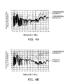
- FIGs. 4A and 4B are characteristic drawings illustrating an EMI of the luminaire.
- FIGs. 4A and 4B results of measurement of the radiating electric field intensity of the power supply apparatus 2 at frequencies from 30MHz to 300 MHz are illustrated.
- a characteristic when the first filter and the second filter are not provided is illustrated by comparative example 1
- a characteristic when only the first filter is provided and the second filter is not provided is illustrated by comparative example 2
- a characteristic when the first filter and the second filter are provided is illustrated by a specific example.
- the radiating electric field intensity may be reduced over an entire range of measurement frequencies in comparison with the case where the first filter 3 is not provided (comparative example 1 in FIG.4A ).
- the radiating electric field intensity may be reduced over the entire range of measurement frequencies in comparison with the case where the first filter 3 is not provided (comparative example 1 in FIG.4A ). Also, with the provision of the first filter 3 and the second filter 5 (specific example in FIG. 4B ), the radiating electric field intensity may be reduced in a range exceeding a frequency of 150 MHz even when comparing with the case where only the first filter 3 is provided and the second filter 5 is not provided (comparative example 2 in FIG. 4A ).
- the common mode current flows through the lines between the switching power supply 4 and the illumination load 6 and the ground while tracing a large loop. It is also supposed that the common mode current may be reduced by providing the second filter 5 between the switching power supply 4 and the illumination load 6 and, consequently, the Electro Magnetic Interference to be radiated may be reduced.
- the Electro Magnetic Interference may be reduced.
- Electro Magnetic Interference may be reduced by reducing the line length L45 between the switching power supply 4 and the second filter 5 to be shorter than the line length L56 between the second filter 5 and the illumination load 6.
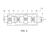
- FIG. 5 is a block diagram illustrating a luminaire including a power supply apparatus according to a second embodiment.
- a luminaire 1a of the second embodiment is configured to have a power supply apparatus 2a instead of the power supply apparatus 2 of the luminaire 1 of the first embodiment.
- the power supply apparatus 2a includes a DC power supply circuit 15 and a smoothing capacitor 16 in addition to the configuration of the power supply apparatus 2 of the first embodiment.
- the configuration of components other than the DC power supply circuit 15 and the smoothing capacitor 16 of the power supply apparatus 2a are the same as the configuration of the luminaire 1.
- the DC power supply circuit 15 is a circuit configured to convert an AC voltage to a DC voltage, and may have an arbitrary configuration as long as the conversion from the AC voltage input from an AC power supply 22 to the DC voltage is achieved.
- the smoothing capacitor 16 is connected between a pair of output terminals of the DC power supply circuit 15 and between a pair of input terminals of the first filter 3.
- the smoothing capacitor 16 is charged by the DC power supply circuit 15, and functions as a DC power supply of the power supply apparatus 2.
- the AC power supply 22 is, for example, a commercial power supply.
- the same effect as the first embodiment may be obtained in the case where the power supply is the AC power supply.
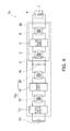
- FIG. 6 is a block diagram illustrating a luminaire including a power supply apparatus according to a third embodiment.
- a luminaire 1b of the third embodiment is configured to have a power supply apparatus 2b instead of the power supply apparatus 2a of the luminaire 1a of the second embodiment.
- the power supply apparatus 2b has a different configuration in the DC power supply circuit 15 in comparison with the power supply apparatus 2a of the second embodiment, and includes a DC power supply circuit 15a instead of the DC power supply circuit 15. Configurations other than the DC power supply circuit 15a of the power supply apparatus 2b are the same as the configurations of the power supply apparatus 2a.
- the DC power supply circuit 15a includes a rectification circuit 17, a third filter 18, a first circuit 19, and a fourth filter 20.
- the DC power supply circuit 15a rectifies an AC voltage supplied from the AC power supply 22 to generate a DC voltage.
- the rectification circuit 17 may have an arbitrary configuration as long as the DC voltage is generated by rectifying the AC voltage.
- the third filter 18 and the fourth filter 20 are, for example, common mode choke coils, and are filters configured to attenuate a common mode current in high-frequency currents flowing between a pair of input terminals (input ports) and a pair of output terminals (output ports) to a level lower than a normal mode current.
- Each of the third filter 18 and the fourth filter 20 may have the same configuration as the first filter 3 or the second filter 5, or may have different configurations. Also, the third filter 18 and the fourth filter 20 may have the same configuration, or may have different configurations.
- the first circuit 19 is connected between the third filter 18 and the fourth filter 20 and, for example, is a circuit configured to perform conversion of the DC voltage or power factor control by driving the switching element so as to be switched.
- the first circuit 19 is, for example, a DC-DC converter, and is, for example, a power factor correction circuit.
- the common mode current may flow through input lines and output lines of the first circuit 19 and hence the Electro Magnetic Interference may be radiated.
- the first circuit 19 is connected between the third filter 18 and the fourth filter 20. Therefore, in the third embodiment as well, the Electro Magnetic Interference may be reduced by reducing the common mode current in the same manner as the effects of the first embodiment.
- the configuration in which the first filter 3, the second filter 5, the third filter 18, and the fourth filter 20 are provided is described in the third embodiment, a configuration in which a filter is provided in one of the switching power supply 4 and the first circuit 19 having a higher switching frequency is also applicable.
- the illumination light source 7 is not limited to the LED, and an EL or an OLED is also applicable.
- the plurality of illumination light sources 7 may be connected to the illumination load 6 in series or in parallel.
Landscapes
- Engineering & Computer Science (AREA)
- Power Engineering (AREA)
- Circuit Arrangement For Electric Light Sources In General (AREA)
- Dc-Dc Converters (AREA)
- Power Conversion In General (AREA)
Applications Claiming Priority (1)
| Application Number | Priority Date | Filing Date | Title |
|---|---|---|---|
| JP2012210197A JP2014068423A (ja) | 2012-09-24 | 2012-09-24 | 電源装置および照明装置 |
Publications (1)
| Publication Number | Publication Date |
|---|---|
| EP2720355A1 true EP2720355A1 (de) | 2014-04-16 |
Family
ID=47605309
Family Applications (1)
| Application Number | Title | Priority Date | Filing Date |
|---|---|---|---|
| EP12195815.1A Withdrawn EP2720355A1 (de) | 2012-09-24 | 2012-12-06 | Stromversorgungsvorrichtung und Leuchte |
Country Status (4)
| Country | Link |
|---|---|
| US (1) | US8917021B2 (de) |
| EP (1) | EP2720355A1 (de) |
| JP (1) | JP2014068423A (de) |
| CN (1) | CN103683902A (de) |
Families Citing this family (11)
| Publication number | Priority date | Publication date | Assignee | Title |
|---|---|---|---|---|
| US20160105097A1 (en) * | 2013-05-13 | 2016-04-14 | Linak A/S | Electric actuator system |
| FI126063B (en) * | 2014-05-21 | 2016-06-15 | Vacon Oy | Limitation of electrical interference |
| KR101591759B1 (ko) * | 2015-09-02 | 2016-02-04 | 주식회사 해찬 | 고효율 oled 제어장치 |
| KR101968585B1 (ko) * | 2016-02-05 | 2019-04-12 | 주식회사 아모텍 | 차동 및 공통 모드 겸용 필터 |
| JP6797748B2 (ja) * | 2017-03-21 | 2020-12-09 | 株式会社東芝 | 電力変換装置及び電力変換システム |
| JP6907784B2 (ja) * | 2017-07-27 | 2021-07-21 | 三菱電機株式会社 | 照明システムおよび照明器具 |
| WO2022138216A1 (ja) * | 2020-12-21 | 2022-06-30 | 株式会社村田製作所 | スイッチング電源装置 |
| CN114270655A (zh) * | 2021-04-17 | 2022-04-01 | 深圳欣锐科技股份有限公司 | 电压转换电路、电压转换装置、电压转换芯片和充电设备 |
| JP7638837B2 (ja) * | 2021-09-16 | 2025-03-04 | シャープ株式会社 | 発光装置 |
| JP2023049905A (ja) * | 2021-09-29 | 2023-04-10 | 東芝ライテック株式会社 | 電源装置 |
| CN117318455A (zh) * | 2022-06-20 | 2023-12-29 | 华为技术有限公司 | 一种电力传输系统和发电系统 |
Citations (5)
| Publication number | Priority date | Publication date | Assignee | Title |
|---|---|---|---|---|
| EP1564875A1 (de) * | 2002-11-11 | 2005-08-17 | The Circle for the Promotion of Science and Engineering | Filter |
| JP2010148333A (ja) * | 2008-12-22 | 2010-07-01 | Sinfonia Technology Co Ltd | 電力変換装置および電源システム |
| EP2408093A2 (de) * | 2010-07-13 | 2012-01-18 | Eaton Aviation Corporation | Inverterfilter mit Differenzialmodus und üblichem Modus sowie System damit |
| US20120153857A1 (en) * | 2010-12-21 | 2012-06-21 | Samsung Electro-Mechanics Co., Ltd. | Power supply and display device including the same |
| WO2012109703A1 (en) * | 2011-02-14 | 2012-08-23 | Kerryj Investment Pty Ltd | Common-mode filter device and system |
Family Cites Families (11)
| Publication number | Priority date | Publication date | Assignee | Title |
|---|---|---|---|---|
| JPS62283612A (ja) * | 1986-05-31 | 1987-12-09 | Toshiba Corp | チヨ−クコイル |
| JPH04320014A (ja) * | 1991-04-18 | 1992-11-10 | Nippon Steel Corp | チョークコイル |
| US20020113559A1 (en) * | 2001-01-26 | 2002-08-22 | Duong Ba Lam | Electronic ballast |
| JP2003018849A (ja) * | 2001-06-29 | 2003-01-17 | Matsushita Electric Works Ltd | 電源装置、及びこれを用いた放電灯点灯装置 |
| JP3883826B2 (ja) * | 2001-07-18 | 2007-02-21 | ソニー株式会社 | スイッチング電源装置 |
| JP4014577B2 (ja) | 2004-03-29 | 2007-11-28 | 株式会社フォースtoフォース | 無電極放電ランプ電源装置 |
| US20070138971A1 (en) * | 2005-08-15 | 2007-06-21 | Liang Chen | AC-to-DC voltage converter as power supply for lamp |
| CN101707435B (zh) * | 2009-05-13 | 2012-02-01 | 海洋王照明科技股份有限公司 | 一种emi滤波电路及使用该滤波电路的led电源驱动电路 |
| CN101707845A (zh) * | 2009-12-02 | 2010-05-12 | 上海宏源照明电器有限公司 | 改善电子镇流器电磁兼容性的方法及电子镇流器 |
| JP5468394B2 (ja) * | 2010-01-13 | 2014-04-09 | 株式会社東芝 | 系統連系インバータ |
| JP5608038B2 (ja) * | 2010-10-25 | 2014-10-15 | パナソニック株式会社 | フィルタ回路およびそれを用いた照明装置 |
-
2012
- 2012-09-24 JP JP2012210197A patent/JP2014068423A/ja active Pending
- 2012-12-06 EP EP12195815.1A patent/EP2720355A1/de not_active Withdrawn
- 2012-12-28 US US13/729,993 patent/US8917021B2/en not_active Expired - Fee Related
-
2013
- 2013-01-21 CN CN201310021784.1A patent/CN103683902A/zh active Pending
Patent Citations (5)
| Publication number | Priority date | Publication date | Assignee | Title |
|---|---|---|---|---|
| EP1564875A1 (de) * | 2002-11-11 | 2005-08-17 | The Circle for the Promotion of Science and Engineering | Filter |
| JP2010148333A (ja) * | 2008-12-22 | 2010-07-01 | Sinfonia Technology Co Ltd | 電力変換装置および電源システム |
| EP2408093A2 (de) * | 2010-07-13 | 2012-01-18 | Eaton Aviation Corporation | Inverterfilter mit Differenzialmodus und üblichem Modus sowie System damit |
| US20120153857A1 (en) * | 2010-12-21 | 2012-06-21 | Samsung Electro-Mechanics Co., Ltd. | Power supply and display device including the same |
| WO2012109703A1 (en) * | 2011-02-14 | 2012-08-23 | Kerryj Investment Pty Ltd | Common-mode filter device and system |
Also Published As
| Publication number | Publication date |
|---|---|
| JP2014068423A (ja) | 2014-04-17 |
| CN103683902A (zh) | 2014-03-26 |
| US20140084791A1 (en) | 2014-03-27 |
| US8917021B2 (en) | 2014-12-23 |
Similar Documents
| Publication | Publication Date | Title |
|---|---|---|
| US8917021B2 (en) | Power supply apparatus and luminaire | |
| US9300241B2 (en) | Methods and systems for reducing conducted electromagnetic interference | |
| JP5908179B2 (ja) | 車両用充電装置 | |
| CN105720823B (zh) | 变压器 | |
| US9516708B2 (en) | Method for operating an LLC resonant converter for a light-emitting means, converter, and LED converter device | |
| US9178485B2 (en) | Methods and systems for reducing conducted electromagnetic interference | |
| JP7087887B2 (ja) | スイッチング電源装置 | |
| JP5916390B2 (ja) | 電源ユニット及びそれを用いたled照明装置 | |
| JP6835082B2 (ja) | 電力変換装置 | |
| CN104969460B (zh) | 使用变压器耦合屏蔽的降噪升降压转换器 | |
| WO2016113949A1 (ja) | 給電装置 | |
| JP5979535B2 (ja) | 照明用非接触給電システムおよびそれを用いた照明器具 | |
| JP5683438B2 (ja) | スイッチング電源装置 | |
| EP2859778B1 (de) | Beleuchtungsvorrichtung für mehrere spannungsquellen | |
| JP6154183B2 (ja) | 照明用led電源回路 | |
| KR101692584B1 (ko) | 조명 장치 | |
| JP5538538B2 (ja) | 少なくとも1つの放電ランプを作動させる電子安定器 | |
| JP2014099309A (ja) | 点灯装置及び照明器具 | |
| JP2022131188A (ja) | 電源装置および照明装置 | |
| JP2022131186A (ja) | 電源装置および照明装置 | |
| CN110266202A (zh) | 一种ac-dc电源模块 | |
| CN105491739A (zh) | Led照明灯的控制系统 |
Legal Events
| Date | Code | Title | Description |
|---|---|---|---|
| PUAI | Public reference made under article 153(3) epc to a published international application that has entered the european phase |
Free format text: ORIGINAL CODE: 0009012 |
|
| AK | Designated contracting states |
Kind code of ref document: A1 Designated state(s): AL AT BE BG CH CY CZ DE DK EE ES FI FR GB GR HR HU IE IS IT LI LT LU LV MC MK MT NL NO PL PT RO RS SE SI SK SM TR |
|
| AX | Request for extension of the european patent |
Extension state: BA ME |
|
| 17P | Request for examination filed |
Effective date: 20140827 |
|
| RBV | Designated contracting states (corrected) |
Designated state(s): AL AT BE BG CH CY CZ DE DK EE ES FI FR GB GR HR HU IE IS IT LI LT LU LV MC MK MT NL NO PL PT RO RS SE SI SK SM TR |
|
| STAA | Information on the status of an ep patent application or granted ep patent |
Free format text: STATUS: THE APPLICATION HAS BEEN WITHDRAWN |
|
| 18W | Application withdrawn |
Effective date: 20150226 |