EP2721929B1 - Pulvérisateur agricole - Google Patents
Pulvérisateur agricole Download PDFInfo
- Publication number
- EP2721929B1 EP2721929B1 EP13189167.3A EP13189167A EP2721929B1 EP 2721929 B1 EP2721929 B1 EP 2721929B1 EP 13189167 A EP13189167 A EP 13189167A EP 2721929 B1 EP2721929 B1 EP 2721929B1
- Authority
- EP
- European Patent Office
- Prior art keywords
- chassis
- self
- sprayer
- supporting frame
- boom
- Prior art date
- Legal status (The legal status is an assumption and is not a legal conclusion. Google has not performed a legal analysis and makes no representation as to the accuracy of the status listed.)
- Not-in-force
Links
- 239000007921 spray Substances 0.000 claims description 12
- 239000007788 liquid Substances 0.000 claims description 9
- 239000012530 fluid Substances 0.000 claims description 2
- 238000005507 spraying Methods 0.000 description 8
- 238000012423 maintenance Methods 0.000 description 5
- 239000006096 absorbing agent Substances 0.000 description 2
- 230000035939 shock Effects 0.000 description 2
- XLYOFNOQVPJJNP-UHFFFAOYSA-N water Substances O XLYOFNOQVPJJNP-UHFFFAOYSA-N 0.000 description 2
- 208000012639 Balance disease Diseases 0.000 description 1
- 238000010276 construction Methods 0.000 description 1
- 230000007423 decrease Effects 0.000 description 1
- 230000000694 effects Effects 0.000 description 1
- 230000002708 enhancing effect Effects 0.000 description 1
- 239000011152 fibreglass Substances 0.000 description 1
- 239000000446 fuel Substances 0.000 description 1
- 230000005484 gravity Effects 0.000 description 1
- 239000002420 orchard Substances 0.000 description 1
- 229910001220 stainless steel Inorganic materials 0.000 description 1
- 239000010935 stainless steel Substances 0.000 description 1
Images

Classifications
-
- A—HUMAN NECESSITIES
- A01—AGRICULTURE; FORESTRY; ANIMAL HUSBANDRY; HUNTING; TRAPPING; FISHING
- A01M—CATCHING, TRAPPING OR SCARING OF ANIMALS; APPARATUS FOR THE DESTRUCTION OF NOXIOUS ANIMALS OR NOXIOUS PLANTS
- A01M7/00—Special adaptations or arrangements of liquid-spraying apparatus for purposes covered by this subclass
- A01M7/0025—Mechanical sprayers
- A01M7/0032—Pressure sprayers
- A01M7/0042—Field sprayers, e.g. self-propelled, drawn or tractor-mounted
Definitions
- This invention relates to a self-propelled agricultural sprayer.
- a typical self-propelled agricultural sprayer consists of a chassis mounting a driving cab, an engine, a tank for liquid to be sprayed, along with associated pumps and pipework, and a foldable spray boom.
- the arrangement of these components will determine the convenience of use and the performance of the sprayer. For example, the ground clearance needs to be sufficient to pass over the crops to be sprayed, and the weight of the 3000-4000 litres of liquid (for example) in the tank, along with that of the other components, needs to be distributed as uniformly as possible across the four wheels of the sprayer. This is further complicated by the fact that the weight of liquid decreases as the spraying operation progresses.
- FR2866787 discloses a self-propelled spraying machine.
- the engine has a frame receiving oscillating and fixed axles at its front and rear or inversely.
- the frame has fixation points at front of a vertical plane and fixation points at rear of a vertical plane for mounting a spraying bar and its lifting system assembly at front/rear of a front or rear wheel and mounting a fuel reservoir and rotary washer block at rear/front of the rear or front wheel.
- US3666177 discloses a self-propelled orchard sprayer.
- the sprayer is single-engined, wherein the fan speed can be pre-set at the optimum value for the job at hand, while the ground speed of the sprayer can be varied at will by the operator, during spraying.
- EP2106935 discloses a vehicle.
- the vehicle is provided with an axle suspended from a main frame of the vehicle by right- and left-hand pairs of connecting rods. As viewed from the top, one of each of the right- and left-hand pairs of connecting rods crosses the other of the pair of rods, and, as viewed from the side, the right- and left-hand pairs of rods are disposed parallel to each other. This arrangement of the connecting rods results in the axle moving substantially vertically up and down during operation of vehicle over uneven terrain.
- a self-propelled agricultural sprayer comprising a supporting frame or chassis mounted on wheels and having mounted thereon at a front end thereof a driving cab and at the other end thereof a support structure carrying a spray boom, a tank for spray liquid being mounted to the rear of the cab, and a modular power supply unit being mounted between the tank and the support structure, characterised in that the spray boom is mounted on a boom mounting arm in the form of a rectangular frame pivotally mounted on the support structure, the support structure being upstanding from the chassis at a position just forward of the rear wheel axis, the pivoting of the rectangular frame on the support structure being controlled by a pair of hydraulic rams, to enable the boom, detachably mounted on the rearmost part of the arm, to be raised and lowered.
- this arrangement permits the weight of the sprayer to be more evenly distributed between the four wheels under all operating conditions, while permitting a very compact configuration.
- the sprayer can thus be lighter and more economical both to construct and to operate than other types of self-propelled sprayer.
- the mounting of the engine to the rear of the tank also offers the advantage of lower noise in the cab, saving the need for costly noise-reduction measures and improving the working environment for the operator. It is also unnecessary to provide covers for the engine and associated pumps, thus further reducing costs, while improving accessibility for maintenance.
- the tank and the modular power supply unit are both mounted within the wheelbase of the sprayer.
- the boom support is in the form of a pivoting arm, enabling the boom to be lifted between an operative position nearer to the ground and an elevated transport position wherein the boom can be folded against the sides of the sprayer.
- This arrangement is lighter in weight than the more usual vertical slide arrangement employed in many sprayers, and also has the advantage that the weight of the boom is moved forwardly when the boom is lowered for spraying, enhancing stability.
- the modular power unit may be bolted on to the supporting frame or chassis. In this way the modular power unit can readily be removed from the sprayer for maintenance purposes.
- the other components such as the tank for the spray liquid, associated pumps and pipework, the driving cab, and the boom, are also mounted on the supporting frame or chassis in such a manner as to permit their ready removal for maintenance, enabling the sprayer to be easily and economically maintained.
- the self-propelled agricultural sprayer may comprise a supporting frame or chassis carried by two pairs of wheels, each pair of wheels being mounted on downwardly-directed limbs extending from opposed ends of a floating cross-beam secured to an A-frame pivotally connected to the supporting frame or chassis, springs being mounted between the cross-beam and the supporting frame or chassis.
- the springs may comprise adjustable air springs, and usually shock absorbers will be mounted in parallel to the springs.
- This configuration ensures that the load is distributed uniformly when traversing uneven terrain, thereby avoiding tipping or loss of traction.
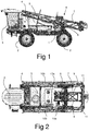
- the self-propelled sprayer has a chassis 1 carried on four wheels 2, each being steerable and driven by a respective hydraulic motor as hereinafter described.
- a driving cab 3 is mounted at the front end of the chassis, forward of the front wheels for maximum visibility.
- the driving cab 3 will contain controls for steering, controlling the speed, and braking of the sprayer, and at least basic controls for the spraying operation, in conventional manner.
- the chassis 1 carries a clean water tank 4 and its associated pump, and to the rear of this is mounted the main spray liquid tank 5, which can be formed of glass-reinforced plastics or stainless steel, for example.
- a modular power supply unit 6 is located on the chassis to the rear of the tank. This consists of a diesel engine and an associated hydraulic pump driven thereby.
- the power supply unit 6 is configured to be secured on the chassis by four bolts, and to permit the ready attaching and detaching of the hydraulic pipes to the pump.
- the pressurised hydraulic fluid supplied by the pump is used to drive the hydraulic motors for each wheel, a hydraulic power steering system, and the sprayer pumps delivering spray liquid to spray nozzles along the boom, as well as a tank wash-out pump connected between the clean water tank 4 and the spray liquid tank 5. Hydraulic power is also used to control the deployment of the boom, as hereinafter described.
- a boom-mounting arm 7 is pivotally mounted on support structure 8 upstanding from the chassis 1 at a position just forward of the rear wheel axis, as can be seen more clearly from Figure 5 .
- the arm 7 is in the form of a rectangular frame, whose pivoting on the support structure 8 is controlled by a pair of hydraulic rams 9, to enable the boom 10, detachably mounted on the rearmost part of the arm 7, to be raised and lowered.
- the boom 10 is formed with two folding sections 10a and 10b on each side of the sprayer, hydraulic rams 11 being provided to rotate the sections 10a and 10b relative to the sprayer and to each other to extend them for use and to fold them inwards for road transit when not spraying.
- the extension and folding of the boom are in most respects conventional, but the mounting of the boom on a pivoting arm structure 7 simplifies lifting and lowering, and reduces the weight of the structure as compare with the conventional sliding elevator arrangement.
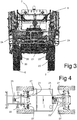
- the wheels 2 are each mounted on a respective limb 20 extending downwardly from a floating cross-beam 21 which is carried on an A-frame 22 ( Figure 4 ), with adjustable air springs 23 mounted between the chassis 1 and the cross-beam 21, along with shock absorbers 24.
- the apex of each A-frame 22 is mounted on a pivot 25 on the chassis which is configured to allow some limited rotation about a longitudinal axis. In this way the mass of the sprayer is distributed more uniformly to the wheels 2.
- the pivot 25 is forward of the respective wheels so that the A-frame 22 is trailing in normal operation.
- Each wheel 2 is driven by a respective hydraulic motor 26 carried by the limb 20, which is itself pivotally connected to the cross-beam 21 with a vertical axis of rotation, hydraulic steering rams 27 extending from the chassis controlling pivoting of the limbs 20 and thus the steering of the sprayer. Individual control of each wheel 2 allows for proper adjustment of track in turning corners.
- the chassis is of relatively simple construction, with all the components being readily demountable therefrom for maintenance, repair or replacement, reducing the cost of maintenance.
Landscapes
- Life Sciences & Earth Sciences (AREA)
- Engineering & Computer Science (AREA)
- Insects & Arthropods (AREA)
- Pest Control & Pesticides (AREA)
- Wood Science & Technology (AREA)
- Zoology (AREA)
- Environmental Sciences (AREA)
- Mechanical Engineering (AREA)
- Special Spraying Apparatus (AREA)
- Catching Or Destruction (AREA)
Claims (6)
- Pulvérisateur agricole automoteur, comprenant un châssis ou cadre de support (1) monté sur des roues (2) et ayant, montée sur celui-ci, à une extrémité avant de celui-ci, une cabine de conduite (3) et, à l'autre extrémité de celui-ci, une structure de support (8) portant une rampe de pulvérisation (10), un réservoir (5) pour pulvériser du liquide étant monté à l'arrière de la cabine (3), et une unité d'alimentation électrique modulaire (6) étant montée entre le réservoir (5) et la structure de support (8), caractérisé par le fait que la rampe de pulvérisation (10) est montée sur un bras de montage de rampe (7) sous la forme d'un cadre rectangulaire monté de manière pivotante sur la structure de support (8), la structure de support (8) étant verticale par rapport au châssis (1) dans une position juste à l'avant de l'essieu de roue arrière, le pivotement du cadre rectangulaire sur la structure de support (8) étant commandé par une paire de vérins hydrauliques (9), pour permettre à la rampe (10), montée de manière détachable sur la partie du bras (7) la plus à l'arrière, d'être relevée et abaissée.
- Pulvérisateur agricole automoteur selon la revendication 1, dans lequel le réservoir (5) et l'unité d'alimentation électrique modulaire (6) sont tous deux montés dans l'empattement du pulvérisateur.
- Pulvérisateur agricole automoteur selon la revendication 1 ou 2, dans lequel l'unité d'alimentation électrique modulaire est montée de manière détachable sur le châssis ou cadre de support et comprend un moteur et une pompe hydraulique pour fournir un écoulement de fluide hydraulique mis sous pression afin d'entraîner des moteurs hydrauliques sur le pulvérisateur.
- Pulvérisateur agricole automoteur selon l'une quelconque des revendications précédentes, dans lequel l'unité d'alimentation électrique modulaire (6) est boulonnée sur le châssis ou cadre de support (1).
- Pulvérisateur agricole automoteur selon l'une quelconque des revendications précédentes, dans lequel le châssis ou cadre de support (1) est porté par deux paires de roues (2), chaque paire de roues étant montée sur des organes dirigés vers le bas (20) s'étendant à partir d'extrémités opposées d'une traverse flottante (21) fixée à un cadre en A (22) relié de manière pivotante au châssis ou cadre de support (1), des ressorts (23) étant montés entre la traverse (21) et le châssis ou cadre de support (1).
- Pulvérisateur agricole automoteur selon l'une quelconque des revendications précédentes, dans lequel les ressorts (23) comprennent des ressorts pneumatiques ajustables.
Applications Claiming Priority (1)
| Application Number | Priority Date | Filing Date | Title |
|---|---|---|---|
| GB1218741.5A GB2507085B (en) | 2012-10-18 | 2012-10-18 | Agricultural sprayer |
Publications (3)
| Publication Number | Publication Date |
|---|---|
| EP2721929A2 EP2721929A2 (fr) | 2014-04-23 |
| EP2721929A3 EP2721929A3 (fr) | 2014-08-06 |
| EP2721929B1 true EP2721929B1 (fr) | 2018-12-12 |
Family
ID=47359095
Family Applications (1)
| Application Number | Title | Priority Date | Filing Date |
|---|---|---|---|
| EP13189167.3A Not-in-force EP2721929B1 (fr) | 2012-10-18 | 2013-10-17 | Pulvérisateur agricole |
Country Status (3)
| Country | Link |
|---|---|
| EP (1) | EP2721929B1 (fr) |
| AU (1) | AU2013245531A1 (fr) |
| GB (1) | GB2507085B (fr) |
Families Citing this family (7)
| Publication number | Priority date | Publication date | Assignee | Title |
|---|---|---|---|---|
| CN106719539B (zh) * | 2016-11-17 | 2020-03-31 | 江苏大学 | 一种多地隙自转向智能喷雾机及控制方法 |
| GB2571670B (en) * | 2016-11-17 | 2022-04-13 | Univ Jiangsu | Multi-ground-clearance self-steering mechanism |
| CN106614474B (zh) * | 2016-11-17 | 2020-11-20 | 江苏大学 | 一种用于田间作业的多地隙自转向机构 |
| CN110876368B (zh) * | 2019-04-01 | 2021-12-31 | 高台县宏丰源农业科技开发有限公司 | 一种自走式多功能高效打药机 |
| CN112075408B (zh) * | 2020-09-08 | 2021-12-03 | 东台汇赢创融科技发展有限公司 | 一种自走式农田喷药机器人 |
| CN112450191A (zh) * | 2020-12-02 | 2021-03-09 | 孔霄 | 一种农业环保型喷药设备 |
| CN113854265B (zh) * | 2021-09-13 | 2023-06-02 | 孙健春 | 一种园林全自动除虫机 |
Family Cites Families (7)
| Publication number | Priority date | Publication date | Assignee | Title |
|---|---|---|---|---|
| FR2080282A5 (fr) * | 1970-02-25 | 1971-11-12 | Mencacci Samuel | |
| JP2002079155A (ja) * | 2000-09-06 | 2002-03-19 | Maruyama Mfg Co Ltd | 薬剤散布車 |
| FR2866787B1 (fr) * | 2004-03-01 | 2006-05-26 | Guy Arnoux | Engin automoteur de pulverisation |
| US7938415B2 (en) * | 2008-03-10 | 2011-05-10 | Deere & Company | Suspended axle for sprayer |
| EP2319305A1 (fr) * | 2009-11-05 | 2011-05-11 | Agco Netherlands B.V. | Système de commande de machine d'application autopropulsée |
| CN202068856U (zh) * | 2011-05-10 | 2011-12-14 | 现代农装科技股份有限公司 | 一种自走式喷杆喷雾机 |
| CN202068857U (zh) * | 2011-05-11 | 2011-12-14 | 现代农装科技股份有限公司 | 自走式喷杆喷雾机 |
-
2012
- 2012-10-18 GB GB1218741.5A patent/GB2507085B/en not_active Expired - Fee Related
-
2013
- 2013-10-17 EP EP13189167.3A patent/EP2721929B1/fr not_active Not-in-force
- 2013-10-18 AU AU2013245531A patent/AU2013245531A1/en not_active Abandoned
Also Published As
| Publication number | Publication date |
|---|---|
| EP2721929A2 (fr) | 2014-04-23 |
| EP2721929A3 (fr) | 2014-08-06 |
| GB2507085A (en) | 2014-04-23 |
| GB201218741D0 (en) | 2012-12-05 |
| GB2507085B (en) | 2018-05-23 |
| AU2013245531A1 (en) | 2014-05-08 |
Similar Documents
| Publication | Publication Date | Title |
|---|---|---|
| EP2721929A2 (fr) | Pulvérisateur agricole | |
| EP2317842B1 (fr) | Machine agricole automotrice d'application | |
| US4685228A (en) | Snow-removing machine | |
| US11686057B2 (en) | Four wheel drive, skid steer snow vehicle with snow plow blade | |
| EP3055194B1 (fr) | Arrangement pour un véhicule motorisé tout terrain et un véhicule motorisé tout terrain équipé d'un tel arrangement | |
| CA2739632C (fr) | Tracteur de faucheuse-andaineuse a bati muni d'une suspension | |
| US2305913A (en) | Spraying apparatus | |
| CA2757092C (fr) | Fleche de pulverisateur a usage agricole dont le mat et la section centrale sont alignes | |
| CA2278073A1 (fr) | Systeme de suspension pour vehicule de servitude | |
| US6460643B1 (en) | Multi-functional self-propelled farm tractor | |
| US3797209A (en) | Variable width front mounted mower | |
| US7478834B2 (en) | Movable concrete pump comprising a distribution boom | |
| CN104285935A (zh) | 一种喷药机 | |
| CN111247892B (zh) | 一种果园作业车 | |
| CN104322300A (zh) | 一种玉米断尖及液体喷雾一体机 | |
| EP2319305A1 (fr) | Système de commande de machine d'application autopropulsée | |
| US20150319924A1 (en) | Swath Roller Attachment for a Swather Tractor | |
| CN103818212B (zh) | 一种离地间隙平稳可调的自走式底盘及调节方法 | |
| CN204120048U (zh) | 一种喷药机 | |
| NL1039524C2 (nl) | Zelfrijdend portaalvoertuig. | |
| US12630988B2 (en) | Snow removal system | |
| EP1310422B1 (fr) | Tracteur avec cadre muni d'éléments supports et d'un bras élévateur | |
| CN219556102U (zh) | 一种可切换移动方式的机场全履带自走式喷药车 | |
| NL1021880C1 (nl) | Trekker voorzien van een frame met afsteunmiddelen en zwenkarm. | |
| RU24337U1 (ru) | Штанговый малообъемный опрыскиватель для обработки полевых культур |
Legal Events
| Date | Code | Title | Description |
|---|---|---|---|
| PUAI | Public reference made under article 153(3) epc to a published international application that has entered the european phase |
Free format text: ORIGINAL CODE: 0009012 |
|
| AK | Designated contracting states |
Kind code of ref document: A2 Designated state(s): AL AT BE BG CH CY CZ DE DK EE ES FI FR GB GR HR HU IE IS IT LI LT LU LV MC MK MT NL NO PL PT RO RS SE SI SK SM TR |
|
| AX | Request for extension of the european patent |
Extension state: BA ME |
|
| PUAL | Search report despatched |
Free format text: ORIGINAL CODE: 0009013 |
|
| AK | Designated contracting states |
Kind code of ref document: A3 Designated state(s): AL AT BE BG CH CY CZ DE DK EE ES FI FR GB GR HR HU IE IS IT LI LT LU LV MC MK MT NL NO PL PT RO RS SE SI SK SM TR |
|
| AX | Request for extension of the european patent |
Extension state: BA ME |
|
| RIC1 | Information provided on ipc code assigned before grant |
Ipc: A01M 7/00 20060101AFI20140701BHEP |
|
| 17P | Request for examination filed |
Effective date: 20150206 |
|
| RBV | Designated contracting states (corrected) |
Designated state(s): AL AT BE BG CH CY CZ DE DK EE ES FI FR GB GR HR HU IE IS IT LI LT LU LV MC MK MT NL NO PL PT RO RS SE SI SK SM TR |
|
| STAA | Information on the status of an ep patent application or granted ep patent |
Free format text: STATUS: EXAMINATION IS IN PROGRESS |
|
| 17Q | First examination report despatched |
Effective date: 20180328 |
|
| GRAP | Despatch of communication of intention to grant a patent |
Free format text: ORIGINAL CODE: EPIDOSNIGR1 |
|
| STAA | Information on the status of an ep patent application or granted ep patent |
Free format text: STATUS: GRANT OF PATENT IS INTENDED |
|
| INTG | Intention to grant announced |
Effective date: 20180514 |
|
| GRAS | Grant fee paid |
Free format text: ORIGINAL CODE: EPIDOSNIGR3 |
|
| GRAA | (expected) grant |
Free format text: ORIGINAL CODE: 0009210 |
|
| STAA | Information on the status of an ep patent application or granted ep patent |
Free format text: STATUS: THE PATENT HAS BEEN GRANTED |
|
| AK | Designated contracting states |
Kind code of ref document: B1 Designated state(s): AL AT BE BG CH CY CZ DE DK EE ES FI FR GB GR HR HU IE IS IT LI LT LU LV MC MK MT NL NO PL PT RO RS SE SI SK SM TR |
|
| REG | Reference to a national code |
Ref country code: GB Ref legal event code: FG4D |
|
| REG | Reference to a national code |
Ref country code: CH Ref legal event code: EP |
|
| REG | Reference to a national code |
Ref country code: AT Ref legal event code: REF Ref document number: 1074793 Country of ref document: AT Kind code of ref document: T Effective date: 20181215 |
|
| REG | Reference to a national code |
Ref country code: DE Ref legal event code: R096 Ref document number: 602013048068 Country of ref document: DE |
|
| REG | Reference to a national code |
Ref country code: IE Ref legal event code: FG4D |
|
| REG | Reference to a national code |
Ref country code: NL Ref legal event code: MP Effective date: 20181212 |
|
| REG | Reference to a national code |
Ref country code: LT Ref legal event code: MG4D |
|
| PG25 | Lapsed in a contracting state [announced via postgrant information from national office to epo] |
Ref country code: LT Free format text: LAPSE BECAUSE OF FAILURE TO SUBMIT A TRANSLATION OF THE DESCRIPTION OR TO PAY THE FEE WITHIN THE PRESCRIBED TIME-LIMIT Effective date: 20181212 Ref country code: NO Free format text: LAPSE BECAUSE OF FAILURE TO SUBMIT A TRANSLATION OF THE DESCRIPTION OR TO PAY THE FEE WITHIN THE PRESCRIBED TIME-LIMIT Effective date: 20190312 Ref country code: FI Free format text: LAPSE BECAUSE OF FAILURE TO SUBMIT A TRANSLATION OF THE DESCRIPTION OR TO PAY THE FEE WITHIN THE PRESCRIBED TIME-LIMIT Effective date: 20181212 Ref country code: LV Free format text: LAPSE BECAUSE OF FAILURE TO SUBMIT A TRANSLATION OF THE DESCRIPTION OR TO PAY THE FEE WITHIN THE PRESCRIBED TIME-LIMIT Effective date: 20181212 Ref country code: ES Free format text: LAPSE BECAUSE OF FAILURE TO SUBMIT A TRANSLATION OF THE DESCRIPTION OR TO PAY THE FEE WITHIN THE PRESCRIBED TIME-LIMIT Effective date: 20181212 Ref country code: BG Free format text: LAPSE BECAUSE OF FAILURE TO SUBMIT A TRANSLATION OF THE DESCRIPTION OR TO PAY THE FEE WITHIN THE PRESCRIBED TIME-LIMIT Effective date: 20190312 Ref country code: HR Free format text: LAPSE BECAUSE OF FAILURE TO SUBMIT A TRANSLATION OF THE DESCRIPTION OR TO PAY THE FEE WITHIN THE PRESCRIBED TIME-LIMIT Effective date: 20181212 |
|
| REG | Reference to a national code |
Ref country code: AT Ref legal event code: MK05 Ref document number: 1074793 Country of ref document: AT Kind code of ref document: T Effective date: 20181212 |
|
| PG25 | Lapsed in a contracting state [announced via postgrant information from national office to epo] |
Ref country code: AL Free format text: LAPSE BECAUSE OF FAILURE TO SUBMIT A TRANSLATION OF THE DESCRIPTION OR TO PAY THE FEE WITHIN THE PRESCRIBED TIME-LIMIT Effective date: 20181212 Ref country code: SE Free format text: LAPSE BECAUSE OF FAILURE TO SUBMIT A TRANSLATION OF THE DESCRIPTION OR TO PAY THE FEE WITHIN THE PRESCRIBED TIME-LIMIT Effective date: 20181212 Ref country code: RS Free format text: LAPSE BECAUSE OF FAILURE TO SUBMIT A TRANSLATION OF THE DESCRIPTION OR TO PAY THE FEE WITHIN THE PRESCRIBED TIME-LIMIT Effective date: 20181212 Ref country code: GR Free format text: LAPSE BECAUSE OF FAILURE TO SUBMIT A TRANSLATION OF THE DESCRIPTION OR TO PAY THE FEE WITHIN THE PRESCRIBED TIME-LIMIT Effective date: 20190313 |
|
| PG25 | Lapsed in a contracting state [announced via postgrant information from national office to epo] |
Ref country code: NL Free format text: LAPSE BECAUSE OF FAILURE TO SUBMIT A TRANSLATION OF THE DESCRIPTION OR TO PAY THE FEE WITHIN THE PRESCRIBED TIME-LIMIT Effective date: 20181212 |
|
| PG25 | Lapsed in a contracting state [announced via postgrant information from national office to epo] |
Ref country code: PL Free format text: LAPSE BECAUSE OF FAILURE TO SUBMIT A TRANSLATION OF THE DESCRIPTION OR TO PAY THE FEE WITHIN THE PRESCRIBED TIME-LIMIT Effective date: 20181212 Ref country code: PT Free format text: LAPSE BECAUSE OF FAILURE TO SUBMIT A TRANSLATION OF THE DESCRIPTION OR TO PAY THE FEE WITHIN THE PRESCRIBED TIME-LIMIT Effective date: 20190412 Ref country code: CZ Free format text: LAPSE BECAUSE OF FAILURE TO SUBMIT A TRANSLATION OF THE DESCRIPTION OR TO PAY THE FEE WITHIN THE PRESCRIBED TIME-LIMIT Effective date: 20181212 Ref country code: IT Free format text: LAPSE BECAUSE OF FAILURE TO SUBMIT A TRANSLATION OF THE DESCRIPTION OR TO PAY THE FEE WITHIN THE PRESCRIBED TIME-LIMIT Effective date: 20181212 |
|
| PG25 | Lapsed in a contracting state [announced via postgrant information from national office to epo] |
Ref country code: RO Free format text: LAPSE BECAUSE OF FAILURE TO SUBMIT A TRANSLATION OF THE DESCRIPTION OR TO PAY THE FEE WITHIN THE PRESCRIBED TIME-LIMIT Effective date: 20181212 Ref country code: EE Free format text: LAPSE BECAUSE OF FAILURE TO SUBMIT A TRANSLATION OF THE DESCRIPTION OR TO PAY THE FEE WITHIN THE PRESCRIBED TIME-LIMIT Effective date: 20181212 Ref country code: SM Free format text: LAPSE BECAUSE OF FAILURE TO SUBMIT A TRANSLATION OF THE DESCRIPTION OR TO PAY THE FEE WITHIN THE PRESCRIBED TIME-LIMIT Effective date: 20181212 Ref country code: IS Free format text: LAPSE BECAUSE OF FAILURE TO SUBMIT A TRANSLATION OF THE DESCRIPTION OR TO PAY THE FEE WITHIN THE PRESCRIBED TIME-LIMIT Effective date: 20190412 Ref country code: SK Free format text: LAPSE BECAUSE OF FAILURE TO SUBMIT A TRANSLATION OF THE DESCRIPTION OR TO PAY THE FEE WITHIN THE PRESCRIBED TIME-LIMIT Effective date: 20181212 |
|
| REG | Reference to a national code |
Ref country code: DE Ref legal event code: R097 Ref document number: 602013048068 Country of ref document: DE |
|
| PLBE | No opposition filed within time limit |
Free format text: ORIGINAL CODE: 0009261 |
|
| STAA | Information on the status of an ep patent application or granted ep patent |
Free format text: STATUS: NO OPPOSITION FILED WITHIN TIME LIMIT |
|
| PG25 | Lapsed in a contracting state [announced via postgrant information from national office to epo] |
Ref country code: AT Free format text: LAPSE BECAUSE OF FAILURE TO SUBMIT A TRANSLATION OF THE DESCRIPTION OR TO PAY THE FEE WITHIN THE PRESCRIBED TIME-LIMIT Effective date: 20181212 Ref country code: DK Free format text: LAPSE BECAUSE OF FAILURE TO SUBMIT A TRANSLATION OF THE DESCRIPTION OR TO PAY THE FEE WITHIN THE PRESCRIBED TIME-LIMIT Effective date: 20181212 Ref country code: SI Free format text: LAPSE BECAUSE OF FAILURE TO SUBMIT A TRANSLATION OF THE DESCRIPTION OR TO PAY THE FEE WITHIN THE PRESCRIBED TIME-LIMIT Effective date: 20181212 |
|
| 26N | No opposition filed |
Effective date: 20190913 |
|
| PG25 | Lapsed in a contracting state [announced via postgrant information from national office to epo] |
Ref country code: TR Free format text: LAPSE BECAUSE OF FAILURE TO SUBMIT A TRANSLATION OF THE DESCRIPTION OR TO PAY THE FEE WITHIN THE PRESCRIBED TIME-LIMIT Effective date: 20181212 |
|
| REG | Reference to a national code |
Ref country code: DE Ref legal event code: R119 Ref document number: 602013048068 Country of ref document: DE |
|
| PG25 | Lapsed in a contracting state [announced via postgrant information from national office to epo] |
Ref country code: MC Free format text: LAPSE BECAUSE OF FAILURE TO SUBMIT A TRANSLATION OF THE DESCRIPTION OR TO PAY THE FEE WITHIN THE PRESCRIBED TIME-LIMIT Effective date: 20181212 |
|
| REG | Reference to a national code |
Ref country code: CH Ref legal event code: PL |
|
| PG25 | Lapsed in a contracting state [announced via postgrant information from national office to epo] |
Ref country code: DE Free format text: LAPSE BECAUSE OF NON-PAYMENT OF DUE FEES Effective date: 20200501 Ref country code: LU Free format text: LAPSE BECAUSE OF NON-PAYMENT OF DUE FEES Effective date: 20191017 Ref country code: LI Free format text: LAPSE BECAUSE OF NON-PAYMENT OF DUE FEES Effective date: 20191031 Ref country code: CH Free format text: LAPSE BECAUSE OF NON-PAYMENT OF DUE FEES Effective date: 20191031 |
|
| REG | Reference to a national code |
Ref country code: BE Ref legal event code: MM Effective date: 20191031 |
|
| PG25 | Lapsed in a contracting state [announced via postgrant information from national office to epo] |
Ref country code: BE Free format text: LAPSE BECAUSE OF NON-PAYMENT OF DUE FEES Effective date: 20191031 |
|
| GBPC | Gb: european patent ceased through non-payment of renewal fee |
Effective date: 20191017 |
|
| PG25 | Lapsed in a contracting state [announced via postgrant information from national office to epo] |
Ref country code: GB Free format text: LAPSE BECAUSE OF NON-PAYMENT OF DUE FEES Effective date: 20191017 Ref country code: IE Free format text: LAPSE BECAUSE OF NON-PAYMENT OF DUE FEES Effective date: 20191017 Ref country code: FR Free format text: LAPSE BECAUSE OF NON-PAYMENT OF DUE FEES Effective date: 20191031 |
|
| PG25 | Lapsed in a contracting state [announced via postgrant information from national office to epo] |
Ref country code: CY Free format text: LAPSE BECAUSE OF FAILURE TO SUBMIT A TRANSLATION OF THE DESCRIPTION OR TO PAY THE FEE WITHIN THE PRESCRIBED TIME-LIMIT Effective date: 20181212 |
|
| PG25 | Lapsed in a contracting state [announced via postgrant information from national office to epo] |
Ref country code: MT Free format text: LAPSE BECAUSE OF FAILURE TO SUBMIT A TRANSLATION OF THE DESCRIPTION OR TO PAY THE FEE WITHIN THE PRESCRIBED TIME-LIMIT Effective date: 20181212 Ref country code: HU Free format text: LAPSE BECAUSE OF FAILURE TO SUBMIT A TRANSLATION OF THE DESCRIPTION OR TO PAY THE FEE WITHIN THE PRESCRIBED TIME-LIMIT; INVALID AB INITIO Effective date: 20131017 |
|
| PG25 | Lapsed in a contracting state [announced via postgrant information from national office to epo] |
Ref country code: MK Free format text: LAPSE BECAUSE OF FAILURE TO SUBMIT A TRANSLATION OF THE DESCRIPTION OR TO PAY THE FEE WITHIN THE PRESCRIBED TIME-LIMIT Effective date: 20181212 |