EP2721992B1 - Flexibles Endoskop mit abnehmbarem Schaft - Google Patents
Flexibles Endoskop mit abnehmbarem Schaft Download PDFInfo
- Publication number
- EP2721992B1 EP2721992B1 EP13188487.6A EP13188487A EP2721992B1 EP 2721992 B1 EP2721992 B1 EP 2721992B1 EP 13188487 A EP13188487 A EP 13188487A EP 2721992 B1 EP2721992 B1 EP 2721992B1
- Authority
- EP
- European Patent Office
- Prior art keywords
- shaft
- handle
- flexible
- component
- disposed
- Prior art date
- Legal status (The legal status is an assumption and is not a legal conclusion. Google has not performed a legal analysis and makes no representation as to the accuracy of the status listed.)
- Active
Links
Images



Classifications
-
- A—HUMAN NECESSITIES
- A61—MEDICAL OR VETERINARY SCIENCE; HYGIENE
- A61B—DIAGNOSIS; SURGERY; IDENTIFICATION
- A61B1/00—Instruments for performing medical examinations of the interior of cavities or tubes of the body by visual or photographical inspection, e.g. endoscopes; Illuminating arrangements therefor
- A61B1/00112—Connection or coupling means
- A61B1/00114—Electrical cables in or with an endoscope
-
- A—HUMAN NECESSITIES
- A61—MEDICAL OR VETERINARY SCIENCE; HYGIENE
- A61B—DIAGNOSIS; SURGERY; IDENTIFICATION
- A61B1/00—Instruments for performing medical examinations of the interior of cavities or tubes of the body by visual or photographical inspection, e.g. endoscopes; Illuminating arrangements therefor
- A61B1/00002—Operational features of endoscopes
- A61B1/00011—Operational features of endoscopes characterised by signal transmission
- A61B1/00016—Operational features of endoscopes characterised by signal transmission using wireless means
-
- A—HUMAN NECESSITIES
- A61—MEDICAL OR VETERINARY SCIENCE; HYGIENE
- A61B—DIAGNOSIS; SURGERY; IDENTIFICATION
- A61B1/00—Instruments for performing medical examinations of the interior of cavities or tubes of the body by visual or photographical inspection, e.g. endoscopes; Illuminating arrangements therefor
- A61B1/00002—Operational features of endoscopes
- A61B1/00057—Operational features of endoscopes provided with means for testing or calibration
-
- A—HUMAN NECESSITIES
- A61—MEDICAL OR VETERINARY SCIENCE; HYGIENE
- A61B—DIAGNOSIS; SURGERY; IDENTIFICATION
- A61B1/00—Instruments for performing medical examinations of the interior of cavities or tubes of the body by visual or photographical inspection, e.g. endoscopes; Illuminating arrangements therefor
- A61B1/00064—Constructional details of the endoscope body
- A61B1/00066—Proximal part of endoscope body, e.g. handles
-
- A—HUMAN NECESSITIES
- A61—MEDICAL OR VETERINARY SCIENCE; HYGIENE
- A61B—DIAGNOSIS; SURGERY; IDENTIFICATION
- A61B1/00—Instruments for performing medical examinations of the interior of cavities or tubes of the body by visual or photographical inspection, e.g. endoscopes; Illuminating arrangements therefor
- A61B1/00064—Constructional details of the endoscope body
- A61B1/00105—Constructional details of the endoscope body characterised by modular construction
-
- A—HUMAN NECESSITIES
- A61—MEDICAL OR VETERINARY SCIENCE; HYGIENE
- A61B—DIAGNOSIS; SURGERY; IDENTIFICATION
- A61B1/00—Instruments for performing medical examinations of the interior of cavities or tubes of the body by visual or photographical inspection, e.g. endoscopes; Illuminating arrangements therefor
- A61B1/00112—Connection or coupling means
- A61B1/00121—Connectors, fasteners and adapters, e.g. on the endoscope handle
- A61B1/00124—Connectors, fasteners and adapters, e.g. on the endoscope handle electrical, e.g. electrical plug-and-socket connection
-
- A—HUMAN NECESSITIES
- A61—MEDICAL OR VETERINARY SCIENCE; HYGIENE
- A61B—DIAGNOSIS; SURGERY; IDENTIFICATION
- A61B1/00—Instruments for performing medical examinations of the interior of cavities or tubes of the body by visual or photographical inspection, e.g. endoscopes; Illuminating arrangements therefor
- A61B1/005—Flexible endoscopes
-
- A—HUMAN NECESSITIES
- A61—MEDICAL OR VETERINARY SCIENCE; HYGIENE
- A61B—DIAGNOSIS; SURGERY; IDENTIFICATION
- A61B1/00—Instruments for performing medical examinations of the interior of cavities or tubes of the body by visual or photographical inspection, e.g. endoscopes; Illuminating arrangements therefor
- A61B1/00002—Operational features of endoscopes
- A61B1/00025—Operational features of endoscopes characterised by power management
- A61B1/00027—Operational features of endoscopes characterised by power management characterised by power supply
- A61B1/00032—Operational features of endoscopes characterised by power management characterised by power supply internally powered
Definitions
- the invention relates to a flexible endoscope as defined in claim 1, and to a method of using a flexible endoscope as defined in claim 14.
- Flexible endoscopes with a handle and a detachable flexible shaft are generally known from US 2011/130627 A1 , US 2008/249355 A1 , US 2007/129604 A1 , US 2009/225159 A1 , WO 02/055126 A2 , WO 2008/086497 A1 , EP 2 055 221 A1 and WO 2008/063565 A2 .
- EP 1 666 684 A1 discloses a leak tester.
- the leak tester can be connected to a measurement object such as an endoscope.
- the leak tester is connected to the measurement object by way of a pipe.
- the leak tester is mainly composed of an air pump, pipes, on/off valves, a relief valve, a gauge pressure sensor and control sections.
- US 7 918 788 B2 discloses an endoscope showing a port disposed on an end section of a flexible hose which is connected to a proximal end of a handle of the endoscope. The port with its valve is involved in pressurizing the endoscope to determine if there is a leakage.
- Endoscope technology has advanced significantly since its initial creation.
- Early endoscopic devices included a rigid, substantially linear shaft permanently attached to a handle, a light delivery system extending from the shaft to the handle and receiving light from an external source, and a plurality of optical lens for transmitting an image to an eyepiece.
- the endoscope has grown increasingly complex, incorporating a flexible shaft, a shaft with a working channel for communicating fluids or medical tools, mechanical components extending from the handle to articulate the shaft, a light source embedded within the handle, optical fiber bundles for transmitting an image from a distal end of the shaft to an eyepiece on the handle, and/or distal imagers.
- endoscope designs have been developed in which sections of the endoscope (e.g., shaft, handle, illumination unit) can be detached by the physician.
- sections of the endoscope e.g., shaft, handle, illumination unit
- Nishigaki discloses a rigid endoscope comprising a rigid shaft fixedly attached to an operating section (handle), wherein the operating section has a connection ring for connecting an imaging unit thereto.
- the endoscope does not allow the shaft to be separated from the handle and instead provides for the imaging unit to be detachable.
- This design of the endoscope has significant drawbacks.
- the shaft is rigid and is not as maneuverable in tight areas of a body cavity as a flexible, articulating shaft.
- the endoscope also requires a rod lens system disposed in the shaft to transfer an optical image to the imaging unit. If there was a problem with the endoscope capturing an image, it may not be readily apparent to the surgeon whether the rod lens system in the shaft and/or the imaging unit was causing the problem. Therefore, both the shaft (with the handle) and the imaging unit would still have to be sent for diagnosis and repair.
- the endoscope comprises a light guide which extends from the handle into the shaft and receives light from an external source. If the light guide is damaged, then the entire endoscope - shaft and handle - has to be sent for repair.
- U.S. Patent No. 4,911,148 to Sosnowski et al. describes an endoscope having a flexible shaft which deflects along an end segment and detaches from a handle.
- the shaft is designed such that an optical image fiber within a fiber post extends outside of the main housing of the shaft. The optical image fiber, therefore, is exposed and susceptible to damage during the process of attaching/detaching the shaft to the handle.
- the deflection mechanism being positioned in the shaft and a deflection control ring being mounted on the handle, an interface adapted for mechanical movement is required at the shaft-handle attachment.
- Dynamic seals are needed to enclose the two sections of the endoscope. However, dynamic seals have a finite lifetime and are prone to wear and leakage.
- Both shaft and handle lack the capability to detect any leaks and discharge any fluids that enter into their interiors.
- the endoscope is configured such that an image is transferred from the optical image fiber in the shaft to an optics module and eyepiece in the handle. If a distorted image was displayed at the eyepiece, the problem could be caused by damage to either the optical image fiber or the optics module. As a result, both the shaft and the handle would still have to be sent to the manufacturer for proper diagnosis and repair.
- a mechanism separate from the coupling unit is provided.
- This mechanism is disposed on the outer surfaces of the shaft and handle and requires that the wires be exposed outside the shaft body.
- the shaft therefore, fails to be completely sealed and cannot prevent leakage of fluid into the interior of the shaft.
- the shaft fails to include a device for detecting and removing fluid therein.
- U.S. Patent Application Publication No. 2010/0191053 to Garcia et al. discloses an articulating endoscope comprising a detachable operator control section, which has a cable wire control system, and a plurality of flexible shaft assemblies.
- the endoscope has a handle-mounted eyepiece attached to an optical fiber bundle in the shaft.
- the shaft is designed with an extreme section extending beyond and outside the shaft's main body, wherein the extreme section is inserted into a cavity in the handle. Within the extreme section are optical image fibers and pull wires. This design has significant drawbacks.
- the extreme section which contains delicate components of the endoscope, is exposed and susceptible to damage during attachment/detachment of the shaft into the handle.
- the shaft and handle also require dynamic seals to accommodate for the interface between the pull wires in the shaft and a handle-mounted steering lever. Because of the drawbacks of dynamic seals, the interiors - and internal components - of the handle and shaft are susceptible to damage and/or contamination by fluid leaking therein.
- a flexible endoscope having a design which provides easier diagnosis and repair of internal components and minimizes the inconveniences associated with repair downtime. It is also desired to provide a detachable shaft flexible endoscope having a coupling mechanism for releasably attaching a flexible shaft to a handle, wherein delicate components are housed safely within the main body of the shaft and/or handle and do not extend or protrude out. It is further desired to provide a detachable and articulating shaft endoscope, wherein the handle and shaft are both protected from fluid leakage - especially at the handle-shaft attachment - when in an attached and detached configuration.
- an object of the present invention to provide an endoscopic instrument having a handle and a flexible shaft, wherein the flexible shaft can easily be attached and detached from the handle.
- the endoscope should be configured such that the internal components that are fragile and delicate are concentrated in one section of the instrument.
- a check valve disposed on said shaft, said check valve communicatively connecting an interior of said shaft to outside and being adapted to indicate a presence of fluid in the interior and discharge any fluid that may have entered into the shaft, wherein said check valve incorporates a vent valve that provides an opening for the release of gas-based fluids contained within the interior of said shaft and for adjusting the pressure inside the interior of said shaft.
- a flexible endoscope system comprising such a flexible endoscope, a handle comprising a plurality of handles, said coupling mechanism releasably attaching the proximal end of said flexible shaft to one of said plurality of handles, a data channel transmitting the image data from an emitting unit to said one of said plurality handles and each of said plurality of handles is adapted to communicate said image data to an auxiliary device.
- the coupling mechanism provides an electrical interface, such as a electrical/power channel, for transferring power that comes from a power source disposed in the handle or is transmitted from an external source through the handle, to an illumination unit (light source) positioned in the flexible shaft.
- the electrical interface may further provide an additional channel, or utilize the same power channel, to enable illumination controls disposed in the handle to adjust the illumination unit.
- the illumination controls may be adapted to change the intensity of the light source.
- the coupling mechanism provides an electrical interface between an imaging unit, and more specifically an image sensor, in the flexible shaft and an imaging controller in the handle.
- the imaging unit generates image data of the area in front of the distal end of the flexible shaft and sends the image data to the controller through a data channel established by the coupling mechanism.
- the controller processes the image data received via the data channel for subsequent display on a monitor or for transmission to an auxiliary or external device, such as a camera control unit (CCU).
- the controller is adapted to control the imaging unit by sending electrical signals through the data channel to the imaging unit.
- the imaging controller may provide means for adjusting in real-time the image quality and characteristics of the image data.
- the electrical interface established by the coupling mechanism can transmit image data as an analog signal.
- the image data can be transmitted through the coupling mechanism in digital format.
- the imaging controller may also be used to fine-tune the focus of the imaging unit or adjust the imaging unit to capture 2D or 3D images.
- the coupling mechanism further provides a power channel for supplying power from the handle to the imaging unit.
- a detachable shaft flexible endoscope having a handle, a flexible shaft, a coupling mechanism for releasably coupling the flexible shaft to the handle, wherein an illumination unit and an imaging unit are both disposed within the flexible shaft.
- the illumination unit includes at least one light source positioned at the proximal end of the flexible shaft and a light-transmitting fiber bundle extending between the light source and the distal end of the flexible shaft, wherein the light-transmitting fiber bundle is adapted to pass light from the light source to the distal end of the flexible shaft. With the light source being disposed at the proximal end, power may be transmitted to thereto directly from the power channel provided by the coupling mechanism.
- the illumination unit comprises a light source disposed at the distal end of the shaft and a power cable conducting electrical power from the power channel of the coupling mechanism to the light source.
- the illumination unit may further include heat-dissipating components to safely distribute heat generated by the light source throughout the flexible shaft.
- the light source may comprise a light emitting diode (LED).
- Other examples of the light source include light emitting electrochemical cells (LEEC), electroluminescent wires, organic light-emitting diodes (OLED), and polymer light-emitting diodes (PLED).
- the imaging unit in some embodiments, it comprises at least one electronic image sensor positioned substantially adjacent to an objective lens/window at the distal end of the flexible shaft.
- the image sensor receives power from the power channel of the coupling mechanism by means of a power cable extending therebetween.
- the power cable used to supply electricity to the light source may also be used to provide electricity to the image sensor. Alternatively, separate power cables may be used to supply power to the light source and the image sensor.
- the imaging unit has at least one electronic image sensor positioned at the proximal end of the flexible shaft and an image-transmitting fiber bundle extending between the image sensor and an objective window disposed at the distal tip of the flexible shaft.
- the imaging unit includes a plurality of image sensors disposed either at the distal end of the flexible shaft or at the proximal end.
- the image sensor incorporated in the flexible shaft may be a Charged Coupled Device (CCD), a Complementary Metal-Oxide Semiconductor (CMOS) device, or any other solid-state imager.
- CCD Charged Coupled Device
- CMOS Complementary Metal-Oxide Semiconductor
- the detachable shaft flexible endoscope may have an articulation unit for deflecting a distal portion of the flexible shaft and thus controlling the orientation of the distal tip of the shaft.
- the distal portion of the flexible shaft can be deflected in any direction (e.g., up, down, left, right, etc.) by a degree of curvature between 0 degrees and at least 285 degrees relative to a longitudinal axis of the flexible shaft (in non-articulated state).
- the articulation unit is disposed within the flexible shaft.
- a steering control i.e., controller or control mechanism for the articulation unit, is also configured on the flexible shaft.
- the steering control is adapted to control the direction and extent of the bending movement of the distal portion of the flexible shaft. Accordingly, all the components related to the articulation/deflection capabilities of the endoscope, i.e., the articulation unit and steering control, are arranged in/on the flexible shaft.
- the articulation unit may comprise at least one tension wire that is coupled to the distal end of the flexible shaft and extends to the steering control.
- a plurality of tension wires may be used in the articulation unit, providing increased precision and accuracy in the deflection of the distal portion of the flexible shaft.
- a tension e.g., pushing, pulling
- the articulation unit may comprise an actuator disposed in the shaft and connected between the steering control and the at least one tension wire.
- a steering signal representing a tensile force and a direction of deflection is sent to the actuator.
- the actuator then applies a tension to the tension wire based on the signal.
- the amount and direction in which the distal portion of the shaft bends is correlated to the applied tensile force.
- the articulation unit is capable of precisely deflecting the flexible shaft in small increments.
- the tension wire disposed in the flexible shaft may comprise any material sufficient to produce the range of motion of the distal portion of the flexible shaft.
- the tension wire may be a mechanical wire.
- the tension wire can be a solid rod or a chain.
- the shape of the detachable shaft flexible endoscope when the shaft and the handle are coupled together is substantially linear in some embodiments.
- the detachable shaft flexible endoscope has a pistol-style shape, wherein the handle provides an ergonomic grip for holding in a user's (medical practitioner, surgeon) hand.
- the pistol shape further accommodates a design feature where the illumination unit, imaging unit, articulation unit, and steering control are all disposed in/on the flexible shaft.
- the pistol style handle provides for the steering control (e.g., finger lever, trigger) to be positioned within reach of the index finger or middle finger of the user's hand.
- this arrangement provides for easier means of locating and diagnosing problems/issues with the endoscope, repairing the instrument, and/or replacing parts of the instrument. More specifically, if the flexible endoscope has a problem with deflecting or providing sufficient illumination, it may be determined quickly that the issue resides in the shaft. The user can then easily detach the malfunctioning shaft, send it to the manufacturer for repair, and substitute/replace the malfunctioning shaft with a new one, without substantial downtime.
- the robust drive electronics e.g., imaging control unit, illumination control
- an endoscope including a handle, a flexible shaft, and a coupling mechanism for attaching the flexible shaft to the handle, the coupling mechanism having a first component disposed on the proximal end of the flexible shaft and a second component disposed on a distal end of the handle, wherein the first and second components are adapted to engage each other.
- the first and second components also independently seal the shaft and handle, respectively, from fluid leakage and contamination with germs, bacteria, or other biological materials.
- the first and second components are adapted to provide fluid-proof, static seals that prevent or reduce the likelihood of communication of fluid into the interior compartments of the flexible shaft and handle.
- the seals enable both parts of the endoscope to be reprocessed (i.e., cleaned, disinfected and sterilized) while in a detached configuration. Further, upon coupling the shaft to the handle, the first and second components collectively create a seal therebetween to prevent any contamination of the interior compartments as well as the coupling mechanism itself.
- the detachable shaft flexible endoscope further comprises at least one leak check valve or port disposed on the flexible shaft.
- the leak check valve functions as a means for verifying that no foreign fluids enter into the interior of the flexible shaft.
- the leak check valve can be configured in an open state so that any fluid that may have entered inside the flexible shaft can be drained or discharged.
- the leak check valve is adapted to receive a tube connected to a suction or pump unit for evacuating any fluids that may have leaked into the interior of the flexible shaft. When the leak check valve is configured in a closed state, the valve forms an air-tight and pressure-tight seal.
- a detachable shaft flexible endoscopic instrument comprising a flexible shaft having a distal end and a proximal and a coupling mechanism adapted to releasably attach one of a plurality of handles to the proximal end of the shaft.
- Each handle has different characteristics and provides different functions when coupled to the flexible shaft.
- a first handle may comprise drive electronics for the imaging unit and the illumination unit as well as an external cable that is adapted to plug into a CCU.
- a second handle may comprise an internal battery and a wireless transmitter-receiver for communicating with the CCU.
- a third handle may comprise an internal battery and an integrated monitor for displaying the image detected by the imaging unit in the flexible shaft.
- a fourth handle may comprise an external cable (i.e., USB) that is adapted to plug into a computer, such as a personal computer, laptop, tablet, iPad, or other processing device.
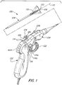
- the flexible endoscope 100 includes a handle 102 and a flexible shaft 104.
- the flexible shaft 104 has a distal end 106 and a proximal end 108, wherein the flexible shaft 104 is adapted to be inserted into a cavity of a living body ("operative site").
- a distal portion (or bending portion) 110 disposed proximally from the distal end 106 can be articulated and deflected in any direction within a plane relative to a longitudinal axis 112, which is defined by the flexible shaft 104.
- the orientation of the distal end 106 can be adjusted by a medical practitioner, e.g., surgeon, using the endoscope ("user").
- the distal end 106 and proximal end 108 are substantially rigid relative to the distal portion 110 of the flexible shaft 104.
- the handle 102 of the endoscope 100 is ergonomically designed for comfortable use by the user. The handle 102 is designed so that the user can easily operate the endoscope 100 using one hand.
- the endoscope 100 - flexible shaft 104 combined with the handle 102 - has a pistol-style shape, wherein the handle 102 resembles a pistol grip.
- the pistol-style shape provides the user a comfortable and easy way of holding the endoscope while operating and controlling its multiple functions. Further, the pistol-style shape provides a structure in which the internal components of the endoscope may be advantageously positioned in or on the flexible shaft and handle.
- the endoscope 100 may have a substantially linear shape, wherein the ergonomic handle is aligned with the flexible shaft.
- the endoscope 100 also has a coupling mechanism 114 which releasably attaches and detaches the flexible shaft 104 to the handle 102.
- the coupling mechanism 114 can be formed with two components, a first component 114a disposed on the proximal end 108 of the flexible shaft 104 and a second component 114b disposed on a distal end 116 of the handle 102.
- the first component 114a is adapted either as a female or male connector while the second component 114b is adapted as a male or female connector, respectively.
- the coupling mechanism 114 provides an electrical interface which connects the internal components of the flexible shaft 104 with the internal components of the handle 102.
- the coupling mechanism 114 further includes a lock 118 to ensure that the flexible shaft 104 and the handle 102 are securely attached to each other. Accordingly, the flexible shaft 104 cannot be inadvertently detached from the handle 102.
- FIG. 3A shows a detailed view of the interior of the flexible shaft 104 of endoscope 100 according to one embodiment.
- Incorporated within the flexible shaft 104 is at least one illumination unit 202 and at least one imaging unit 204. Both the illumination unit 202 and the imaging unit 204 extend the length of the flexible shaft 104, from the distal end 106 to the first component 114a of the coupling mechanism 114 at the proximal end 108.
- the illumination unit 202 comprises a light source 208 disposed at the distal end 106 and a power cable 210 connected to the light source 208 for providing electrical power to the light source 208.
- the light source 208 is a light emitting diode (LED), such as organic light emitting diodes, polymer light emitting diodes, and solid-state lighting.
- LED light emitting diode
- Other examples of lights sources that may be used in the endoscope include light emitting electrochemical cells (LEEC) and electroluminescent wires.
- LEEC light emitting electrochemical cells
- the light source 208 is further mounted substantially adjacent to a window 212 at a distal tip 120 of the distal end 106. Upon receiving electrical power, the light source 208 shines light through the window 212 to an area in front of the distal end 106 of the flexible shaft 104.
- the imaging unit 204 comprises an image sensor 214 mounted at the distal end 106 and substantially adjacent to an objective lens 218 at the distal tip 120.
- the image sensor is a solid state image sensor.
- the image sensor 214 may be implemented as a charge-coupled device (CCD), a complementary symmetry metal-oxide semiconductor (CMOS) active pixel image sensor, a camera or any other commercially available imaging device.
- CCD charge-coupled device
- CMOS complementary symmetry metal-oxide semiconductor
- the image sensor 214 receives power from the power cable 210, it operates to capture an image of the area in front of the distal end 106 of the flexible shaft 104, i.e. operative site. More specifically, the objective lens 218 directs the image towards the image sensor 214.
- the image sensor 214 converts the image into image data.
- the image sensor 214 generates the image data in analog form, whereas in another embodiment, it generates image data in digital form.
- the imaging unit 204 further comprises an image-transmitting cable 216 for transmitting the image data from the image sensor 214 to the coupling mechanism 114 and thereafter to an imaging controller in the handle 102.
- the flexible shaft 104 can also be equipped with an articulation unit 206 for bending/deflecting the distal portion 110 of the flexible shaft 104.
- the articulation unit 206 extends within the shaft between the distal end 106 to a steering control 122 positioned on the shaft proximate to the proximal end 108.
- the articulation unit 206 as shown in FIG. 3A , comprises at least one tension wire 220 passing through a lumen 222.
- the tension wire 220 comprises a mechanical wire in some embodiments. In other embodiments, the tension wire 220 comprises a solid rod or a chain. One end of the tension wire 220 is embedded in the distal end 106 while an opposite end of the tension wire 220 is operably connected to the steering control 122.
- the bending portion 110 of the flexible shaft 104 can be articulated away from the longitudinal axis 112.
- the articulation unit 206 therefore, can deflect the distal end 106 to adjust the orientation of the distal tip 120.
- the operative site where the image sensor and the light source are focused may be changed without having to shift the entire endoscopic instrument and more specifically the handle 102.
- the articulation unit 206 can deflect the distal end 106 in any direction (360 degrees) with respect to the longitudinal axis 112 of the shaft.
- the distal end can deflect up or down, left or right, or any combination of the relative directions.
- the distal portion 110 can be deflected by a degree of curvature between 0 degrees and at least 285 degrees relative to the longitudinal axis 112.
- the detachable shaft flexible endoscope 100 can further include a working channel 224.
- the structure of the working channel 224 is defined by a central lumen disposed within the flexible shaft 104, as illustrated in FIG. 3A .
- the working channel 224 has an inlet port 226 disposed substantially at the proximal end 108 of the flexible shaft 104 and an outlet port 228 at the distal tip 120.
- the inlet port 226 is integrated with the exterior surface of the flexible shaft 104 and provides access to the working channel 224.
- the purpose of the working channel is to provide passage for fluids and/or medical instruments into the body cavity. In particular, fluids or medical instruments can be inserted into the working channel 224 through the inlet port 226 and guided towards and out of the outlet port 228.
- FIG. 3B shows another embodiment of the flexible shaft 104.
- the flexible shaft 104 comprises an illumination unit 202 and imaging unit 204 extending the length of the flexible shaft 104, between the distal tip 120 and the proximal end 108 as well as an articulation unit 206 connected between the distal end 106 and a steering control 122 positioned proximate to the proximal end 108.
- the illumination unit 202 comprises a light source 252, such as a LED, disposed at the proximal end 108 of the flexible shaft 104, and power cable 256 connected to the light source 252 for providing electrical power thereto. Since the light source 252 is located away from the distal tip 120 of the shaft 104, a light-transmitting fiber bundle 254 is used to conduct light from the light source 252 to the window 212.
- the imaging unit 204 may have the same distal configuration as the imaging unit 204 shown in FIG. 3A .
- the imaging unit 204 has an image sensor 214 positioned substantially adjacent to the objective lens 218 at the distal end 106 of the shaft.
- the imaging unit 204 may have a proximal configuration.
- the image sensor may be disposed at or proximate to the proximal end 108.
- an image-transmitting fiber bundle is connected therebetween. An image of the operative site is directed into the image-transmitting fiber bundle, which then transmits the optical image to the image sensor.
- the image sensor subsequently captures the image and converts it into image data, either in analog or digital signal form.
- An image-transmitting cable 216 disposed in the flexible shaft 104 is used to transmit the image data from the proximal image sensor to the coupling mechanism 114.
- the articulation unit 206 may comprise at least one tension wire 264 (e.g., mechanical wire, solid rod, chain) and an actuator 266.
- the tension wire 264 is positioned within a lumen 270 and has a first end embedded in the distal end 106 of the flexible shaft 104 and a second end connected to the actuator 266.
- the actuator 266 is adapted to adjust the tension in the tension wire 264, thereby deflecting the distal portion 110 of the flexible shaft 104.
- the actuator 266 may comprise a piezoelectric motor in some embodiments.
- the actuator 266 is in operable connection with the steering control 122 located near the proximal end 108 of the shaft.
- a steering signal for controlling the deflection of the distal portion is generated by moving the steering control 122.
- the steering signal is subsequently transmitted from the steering control 122 to the actuator 266, wherein the steering signal establishes the amount of tension the actuator 266 must apply to the tension wire 264.
- the bending portion 110 of the shaft articulates in a plane relative to the longitudinal axis 112.
- the steering control 122 comprises at least one lever member or pistol trigger for controlling the articulation of the distal portion 110.
- the steering control also includes a ring portion for receiving the index or middle finger of the user.
- the lever arm moves in a single plane, indicated by the arrow 130. Such single plane movement of the lever arm corresponds to a movement of the distal portion 110.
- the steering control 122 being disposed proximate to the proximal end 108, the user can readily access the steering control 122 with his or her index or middle finger, while still being able to maintain his or her grip on the handle 102 and to access other control buttons 404 (discussed further below) positioned on the handle 102. It is therefore very simple to actuate the distal portion 110 of the shaft and adjust the illumination unit and/or imaging unit via buttons 404 simultaneously.
- the flexible shaft 104 may be equipped with two levers in order to articulate the distal portion 110 in multiple planes.
- the flexible shaft 104 can incorporate more than one illumination unit and/or imaging unit.
- the flexible shaft 104 can have two imaging units 204 capturing an image through two objective lenses 218 at the distal tip 120. With two imaging units, the image data from both image sensors can be used to create a three-dimensional stereoscopic image for display.
- the flexible shaft 104 can also have two or more illumination units 202 to provide increased lighting through the windows 212 to the area in front of the distal end of the shaft. The two or more illumination units 202 may also be used to provide different forms of illumination.
- the illumination units can differ in terms of their color spectrum.
- the illumination units may differ in terms of their light source type, e.g., LEDs, LEEC, electroluminescent wires, OLEDs, and PLEDs.
- the articulation unit 206 may comprise multiple tension wires 220 to provide for deflection of the distal portion 110 of the flexible shaft 104.
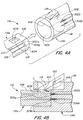
- FIGS. 4A-4B show one example of the coupling mechanism 114.
- a first component 114a (“male component”) and a second component 114b (“female component”), wherein the first component is adapted to engage or insert into the second component.
- a locking mechanism 118 is also provided, wherein after the first and second components are mated with each other, the lock - upon engagement/activation - establishes a secure attachment therebtween.
- the first component 114a is disposed on the proximal end 108 of the shaft 104 while the second component 114b is disposed on the distal end 116 of the handle 102.
- the components may be positioned in opposite manner, such that the first component is located on the distal end of the handle and the second component is located on the proximal end of the shaft.
- the first component 114a of the coupling mechanism may comprise merely a portion of the distal end 108 of the flexible shaft 104 ( FIGS. 4A-4B ).
- the first component 114a can be shaped such that its cross section is partially non-circular. As shown in FIG. 4A , the cross section of the first component 114a can have a semicircular shape with a flat side 616.
- the second component 114b comprises a recess 602 formed on the distal end 116 of the handle 102.
- the recess 602 is designed with a preset depth such that upon mating the two components, the proximal end face 604 of the shaft 104 contacts the distal end face 606 of the handle 102.
- the recess 602 has a cross-sectional shape which corresponds to the non-circular cross section of the first component 114a.
- first and second components having complimentary non-circular cross-sectional profiles, a fitted arrangement is created therebetween.
- the lock 118 may comprise a lever disposed on the distal end 116 of the handle 102 and an aperture 608 that is formed in the flat side 616 of the first component 114a.
- the lever of lock mechanism 118 is pivotably mounted to the outer surface of the distal end 116, by way of a support shaft 610, so as to oppose the flat side 618 of the recess 602.
- a hook 612 is disposed at the distal end of the lever and inwardly projected from the flat side 618 of the recess 602.
- a coil spring 614 is attached to the shaft 610 in order to pivotably force the lever in a direction C.
- the hook 612 latches onto/within the aperture 608 by force of the coil spring 614.
- the proximal end face 604 is fixed to and placed in pressing contact with the distal end face 606 due to the hook 612 being lodged within the aperture 608. Accordingly, a secure attachment is automatically achieved between the flexible shaft 104 and the handle 102 once the first and second components 114a, 114b are fully mated to each other.
- the user In order to detach the shaft 104 from the handle 102, the user merely unlocks the locking mechanism 118 (e.g., pivot the lever of lock 118 so that the hook 612 no longer latches to aperture 608) and withdraw the first component 114a from within the recess 602 of the second component 114b.
- the locking mechanism 118 e.g., pivot the lever of lock 118 so that the hook 612 no longer latches to aperture 608
- the coupling mechanism 114 is adapted to provide seals to inhibit fluid communication into the interiors of the handle and the shaft and thus reduce the likelihood of contamination of internal components (e.g., illumination unit, imaging unit, drive electronics).
- the first component 114a forms a first seal along the proximal end face 604 to prevent the ingress of foreign fluid into the shaft.
- the second component 114b independently forms a second seal on the distal end face 606, thereby preventing the ingress of foreign fluid into the handle 102.
- the internal components within the handle 102 and shaft 104 are substantially protected from fluid contact, which reduces the likelihood that they will be susceptible to damage. Moreover, the seals of the first and second components prevent any contamination of the interiors of the handle and shaft with germs, bacteria, and other biological material. Since the articulation unit and steering control are positioned on the flexible shaft, the coupling mechanism does not need to provide an interface adapted for mechanical movement and thus the first and second components may provide static seals.
- first and second components 114a, 114b When the first and second components 114a, 114b are mated to each other, an external seal is created along the coupling mechanism between the shaft and handle.
- the first and second components may be adapted with additional features, e.g., protrusions, projections, rubber washers, to reduce the likelihood that foreign fluid is communicated into a region between the shaft and handle within the coupling mechanism 114.
- the external seal similarly reduces the likelihood that the interiors of the handle and shaft will be exposed to foreign fluid and other contaminants.
- the detachable shaft flexible endoscope according to the present invention can incorporate other coupling mechanisms which provide a secure, sealed attachment between the flexible shaft 104 and the handle 102.
- a coupling mechanism using magnetic fastening means can be used to securely attach the flexible shaft 104 to the handle 102.
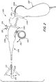
- the endoscope 100 is equipped with a check valve 124 mounted to the flexible shaft 104 ( FIGS. 1-2 ).
- the check valve 124 is adapted to indicate a presence of fluid in the interior of the shaft 104 as well as discharge any fluid that may have entered into the shaft. By positioning all the delicate components within the shaft, only one check valve is required.
- the handle 102 contains more robust elements, such as drive electronics for controlling the illumination unit and the imaging unit, and therefore does not require a check valve.
- the check valve 124 is communicatively connected to the interior of the shaft 104 containing the illumination unit 202 and the imaging unit 204. If the check valve lever is configured in the open position, the check valve 124 is placed in communicative connection with the outside, i.e., outside environment. The check valve may then be used to remove any fluid that may be present in the shaft interior. In some embodiments, the check valve 124 may be adapted to connect to a pump or suction unit for evacuating the interior of the shaft of any and all fluids present threrein. Conversely, if the check valve lever is closed, the connection to the interior of the shaft is restricted.
- the check valve 124 further incorporates a vent valve 126, which provides an opening for the release of gas-based fluids contained within the interior of the shaft and for adjusting the pressure inside the interior of the shaft ( FIGS. 1-2 ).
- the vent valve 126 may be closed.
- the vent valve 126 may be used to perform a leak test, wherein an air supply unit is connected thereto to feed air into the shaft interior.
- the coupling mechanism 114 creates interface connections between the internal components of the flexible shaft 104 and the handle 102.
- the coupling mechanism 114 provides at least one electrical interface for each the illumination unit 202 and the imaging unit 204. Since the articulation unit 206 and the steering control 122 are located in the shaft, no dynamic mechanical interfaces are required.
- the coupling mechanism 114 establishes a power channel 302 for conducting electrical power from the handle 102 to the power cable 210 (or 256) in the flexible shaft 104.
- the power channel 302 comprises a pin 302b disposed on the distal end face 606 of the handle and a contact region 302a disposed on the proximal end face 604 of the flexible shaft.
- the pin 302b and the contact region 302a are aligned longitudinally and radially in a matching pattern so that when the first and second components 114a, 114b are mated, the pin 302b contacts the corresponding contact region 302a. Accordingly, by engaging the first component with the second component, the pin 302b is positioned in matching arrangement with the contact region 302a. No additional adjustment is required in order to properly establish physical and electrical contact between the pin and contact region.
- a data channel 304 is further provided by the coupling mechanism 114.
- the data channel 304 is created by a pin 304b making contact with a contact region 304a.
- the pin 304b is electrically connected to an image-transmitting cable 428, which in turn is connected to an imaging controller 402 (discussed further below) inside the handle.
- the contact pad 304a is electrically connected to the image-transmitting cable 216 in the flexible shaft 104.
- the power channel 302 and the data channel 304 may comprise a pogo pin or spring-loaded pin and a contact pad.
- the pogo pins are embedded in the distal end face 606 of the handle 102 while the contact pads 302a are positioned on the proximal end 604 in axial alignment with the pogo pins.
- the pogo pins maintain constant contact with the contact pads.
- the contact pads can be adapted to have a wider surface area than the tip of the pogo pins to account for potential deviations in alignment. This ensured that proper contact is made between the pins and pads.
- conventional electrical pins and contact housings e.g., sockets
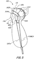
- the handle 102 of the detachable shaft flexible endoscope 100 is shown.
- the handle 102 includes the drive electronics for the controlling the illumination unit 202 and the imaging unit 204.
- an image controller 402 is disposed within the handle 102, wherein the controller 402 is adapted to process and convert the image data received via the data channel of the coupling mechanism 114 into a format suitable for transmission and display on a monitor.
- the controller 402 can encode/decode the image data as well as adjust the image data to alter how the image is displayed on a display unit.
- a user can adjust the image quality of the image data, such as increasing or decreasing the resolution (e.g., pixel resolution, spatial resolution, spectral resolution, temporal resolution).
- the controller 402 may be adapted to adjust the image quality between 2D display and 3D display.
- the image controller 402 has the capability to perform stereoscopy or 3D imaging to provide depth in the image data.
- the controller 402 can also transmit a signal to the image sensor 214 to adjust various settings of the sensor. For example, a control signal can be sent to the image sensor to zoom in or zoom out on the operative site.
- the control pad 404 and controller 402 the user may be able to adjust the focus of the image sensor and improve the clarity of the image data received by the controller.
- An illumination control unit 406 connected to the control pad 404 can also be incorporated within the handle 102, wherein the illumination control 406 adjusts the light source 208 (or 252).
- the illumination control 406 can function to turn on or off the light source.
- the intensity of the light projected from the light source can be increased or decreased by the user via the control pad 404 and illumination control 406. Where the endoscope 100 includes more than one type of light source, the user can adjust which type of lighting to use at any given moment.
- the handle 102 also includes a power cable 426 to provide electrical power to the illumination unit 202 and the imaging unit 204 via the electrical channel 302 of the coupling mechanism.
- the power cable 426 receives electrical power from an internal battery source disposed in the handle 102.
- the power cable 426 feed electrical power to internal components of the shaft from an external power source, which is connected to the handle 102.
- control pad 404 can include a battery status indicator, which displays whether the endoscope 100 is being powered by an external source or by an internal battery, and shows battery life.
- FIG. 6 shows another embodiment of the detachable shaft flexible endoscope, and more specifically, a flexible endoscope system 700.
- the endoscope system 700 comprises a flexible shaft 704 having a distal end and a proximal end.
- An illumination unit and imaging unit are both disposed within the flexible shaft.
- the shaft 704 includes an articulation unit which articulates a distal portion of the shaft 704 when a steering control is moved.
- the shaft 704 may also comprise a check valve that is adapted to indicate/detect and discharge any fluid that may have entered into an interior of the shaft.
- the endoscope 700 also comprises a coupling mechanism 714 for releasably attaching the proximal end 708 of the shaft to one of a plurality of handles 710, 712, 714, 716, wherein the handles each have different capabilities and functions.
- handles 710, 712 each have the same configuration of handle 102 ( FIG. 5 ) and further have external cables 730, 740 that are adapted to plug into auxiliary devices 732, 742, respectively.
- the external cables 730, 740 provide the means for the handles 710, 712 to communicate image data received from the imaging unit to the auxiliary devices.
- the auxiliary devices are adapted to then process and manipulate the image data for display on a monitor 734, 744.
- the auxiliary devices may also perform image optimization as well as record/save the image data.
- the external cable also transmits electrical power supplied by the auxiliary device to the handle and the shaft.
- the external cable 730 connects to a camera control unit (CCU) 732, which displays the image data on the monitor 734.
- the CCU 732 is adapted to drive the imaging unit and control various parameters thereof to adjust the quality of the image data.
- the external cable 740 of handle 712 can connect to a computer 742, such as a desktop, laptop, netbook, tablet, and iPad. Similar to the CCU 732, the computer 742 is adapted to receive and process image data and send the resulting image to a monitor 744.
- the handle 714 comprises an internal battery pack 750 to provide electrical power to the drive electronics present in the handle and the internal components of the shaft.
- a transmitter-receiver unit 752 is integrated with the handle 714, providing wireless communication between the endoscope 700 and an auxiliary device 754. As shown in FIG. 6 , the transmitter-receiver unit 752 wirelessly transmits image data to a CCU 754 for display on a monitor 756 and may receive control signals from the CCU. Examples of wireless technology used by the transmitter-receiver unit include radio frequency communication, infrared short-range communication, Bluetooth, and ultra-wideband communication.
- the handle 716 differs from the other handles because it includes an internal battery source 760 and has an auxiliary device 762 directly integrated therein.
- a video screen 762 is directly mounted to the handle 716.
- the video screen 762 may comprise an LCD screen.
- the video screen 762 may comprise an OLED screen.
- the control pad 404 may be consolidated with the video screen 762, such that menu options are provided and selectable through touch-screen features.
- the shaft 704 with the coupling mechanism forms a modular element that they can be readily connected to one of multiple handles.
- the shaft 704 is versatile.
- a method of using this medical instrument is disclosed.
- a user mates a first component 114a of the coupling mechanism 114 with a second component 114b of the coupling mechanism 114, and locks the two components securely together using a lock mechanism 118.
- the flexible shaft 104 and the handle 102 align and couple with each other along the longitudinal axis 112 while the pins 302b, 304b connect with the contact regions 302a, 304a.
- the lock 118 is engaged, the flexible shaft 104 and handle 102 are securely fixed to each other.
- the user then checks to see if any fluid previously entered into the interior of the shaft 104, using the check valve 124. The user may then discharge any foreign fluid through the check valve. At this point, the user can begin using the endoscope 100 to examine a body cavity. Once the surgeon has finished using the endoscope 100, it can be reprocessed and made sanitary either in an attached or detached configuration.
Landscapes
- Health & Medical Sciences (AREA)
- Life Sciences & Earth Sciences (AREA)
- Surgery (AREA)
- Engineering & Computer Science (AREA)
- Biomedical Technology (AREA)
- Molecular Biology (AREA)
- Pathology (AREA)
- Radiology & Medical Imaging (AREA)
- Nuclear Medicine, Radiotherapy & Molecular Imaging (AREA)
- Biophysics (AREA)
- Physics & Mathematics (AREA)
- Heart & Thoracic Surgery (AREA)
- Medical Informatics (AREA)
- Optics & Photonics (AREA)
- Animal Behavior & Ethology (AREA)
- General Health & Medical Sciences (AREA)
- Public Health (AREA)
- Veterinary Medicine (AREA)
- Computer Networks & Wireless Communication (AREA)
- Endoscopes (AREA)
- Instruments For Viewing The Inside Of Hollow Bodies (AREA)
Claims (14)
- Flexibles Endoskop, das Folgendes aufweist:einen Handgriff (102, 710, 712, 714, 716);einen flexiblen Schaft (104) mit einem distalen Ende (106) und einem proximalen Ende (108);einen Koppelmechanismus (114), der den Handgriff (102, 710, 712, 714, 716) lösbar am proximalen Ende (108) des flexiblen Schafts (104) befestigt;eine Beleuchtungseinheit (202), die im flexiblen Schaft (104) angeordnet ist, wobei die Beleuchtungseinheit (202) einen Bereich vor dem distalen Ende (106) des flexiblen Schafts (104) mit Licht versorgt; undeine Bildgebungseinheit (204), die im flexiblen Schaft (104) angeordnet ist, wobei die Bildgebungseinheit (204) Bilddaten des Bereichs vor dem distalen Ende (106) des flexiblen Schafts (204) erzeugt;wobei der Koppelmechanismus (114) einen elektrischen Kanal (302) zur Übertragung von elektrischer Energie zur Beleuchtungseinheit (202) und zur Bildgebungseinheit (204), und einen Datenkanal (304) zur Übertragung der Bilddaten von der Bildgebungseinheit (204) umfasst,dadurch gekennzeichnet, dassam Schaft (104) ein Absperrventil (124, 126) angeordnet ist, wobei das Absperrventil (124, 126) einen Innenraum des Schafts (104) kommunizierend nach außen verbindet und dazu eingerichtet ist, eine Anwesenheit eines Fluids im Innenraum anzuzeigen und jegliches Fluid, das in den Schaft (104) eingetreten sein kann, abzulassen; unddas Absperrventil (124, 126) ein Entlüftungsventil (126) umfasst, das eine Öffnung für das Ablassen gasbasierter Fluide bereitstellt, die im Innenraum des Schafts (104) enthalten sind, und zur Einstellung des Drucks im Innenraum des Schafts (104).
- Flexibles Endoskop gemäß Anspruch 1, wobei der Koppelmechanismus (114) eine erste Komponente (114a), die am proximalen Ende (108) des flexiblen Schafts (104) angeordnet ist, und eine zweite Komponente (114b) umfasst, die am Handgriff (102) angeordnet ist, wobei die erste Komponente (114a) und die zweite Komponente (114b) komplementäre Formen aufweisen, wobei die erste Komponente (114a) mit der zweiten Komponenten (114b) verriegelt wird, um eine sichere Verbindung dazwischen zu erzeugen.
- Flexibles Endoskop gemäß Anspruch 2, wobei die erste Komponente (114a) eine erste Dichtung mit dem Schaft (104) bildet, und wobei die zweite Komponente (114b) eine zweite Dichtung mit dem Handgriff (102) bildet, wobei die erste und zweite Dichtung unabhängig voneinander die Wahrscheinlichkeit einer Übertragung eines Fluids in den Innenraum des Schafts (104) bzw. einen Innenraum des Handgriffs (102) reduzieren.
- Flexibles Endoskop gemäß irgend einem der Ansprüche 1 - 3, ferner aufweisend eine Steuerung (402), die im Handgriff (102) angeordnet ist, wobei die Steuerung (402) die Bilddaten zur Verarbeitung in ein Datenformat zum Anzeigen empfängt, und ein Steuersignal zur Anpassung einer Bildqualität der Bildgebungseinheit über den Datenkanal (304) übermittelt.
- Flexibles Endoskop gemäß irgend einem der Ansprüche 1 - 4, wobei die Beleuchtungseinheit (202) Folgendes aufweist:zumindest eine lichtemittierende Diode (LED), die im Schaft (102) angeordnet ist;einen Bildsensor (214), der beim distalen Ende (106) des flexiblen Schafts (104) angeordnet ist, wobei der Bildsensor (214) ein Bild des Bereichs vor dem distalen Ende (106) des flexiblen Schafts (104) erfasst und Bilddaten erzeugt;ein Bildübertragungskabel (216) zur Übertragung der Bilddaten zum Datenkanal (304) des Koppelmechanismus (114); undzumindest ein Energiekabel (210) zur Übertragung elektrischer Energie vom elektrischen Kanal (302) des Koppelmechanismus zur LED und zum Bildsensor (214).
- Flexibles Endoskop gemäß irgend einem der Ansprüche 1 - 5, ferner aufweisend:eine Auslenkeinheit (206), die im flexiblen Schaft (104) angeordnet ist, wobei die Auslenkeinheit (206) dazu angepasst ist, einen distalen Abschnitt (110) des flexiblen Schafts (104) in einer Ebene zu biegen; undeine Lenkungssteuerung (122), die im flexiblen Schaft (104) dem proximalen Ende benachbart angeordnet ist, wobei die Lenkungssteuerung (122) die Biegung des distalen Abschnitts (110) des flexiblen Schafts (104) steuert.
- Flexibles Endoskop gemäß irgend einem der Ansprüche 1 - 6, wobei der flexible Schaft (104) einen Eingangsanschluss (226), der beim proximalen Ende (108) positioniert ist, einen Ausgangsanschluss (228), der im distalen Ende (106) gebildet ist, und einen Arbeitskanal (224) aufweist, der sich zwischen dem Eingangsanschluss (226) und dem Ausgangsanschluss (228) erstreckt, wobei der Arbeitskanal (224) einen Durchgang für Fluide oder ein medizinisches Instrument bereitstellt.
- Flexibles Endoskopiesystem, das Folgendes aufweist:ein flexibles Endoskop gemäß Anspruch 1;eine Mehrzahl von Handgriffen (102, 710, 712, 714, 716);wobei der Koppelmechanismus (114) das proximale Ende (108) des flexiblen Schafts lösbar mit einem Handgriff aus der Mehrzahl von Handgriffen (102, 710, 712, 714, 716) verbindet;wobei der Datenkanal (304) die Bilddaten von der Bildgebungseinheit (204) zu dem einen Handgriff der Mehrzahl von Handgriffen (102, 710, 712, 714, 716) überträgt; undwobei jeder Handgriff der Mehrzahl von Handgriffen (102, 710, 712, 714, 716) dazu angepasst ist, die Bilddaten zu einer Zusatzeinrichtung (732, 742, 744, 762) zu übermitteln.
- Flexibles Endoskopiesystem gemäß Anspruch 8, wobei der Koppelmechanismus (114) eine erste Komponente (114a), die beim proximalen Ende (108) des flexiblen Schafts (104) angeordnet ist, und eine zweite Komponente (114b) aufweist, die bei jedem Handgriff der Mehrzahl von Handgriffen (102, 710, 712, 714, 716), wobei die erste Komponente (114a) und die zweite Komponente (114b) komplementäre Formen aufweisen, wobei die erste Komponente (114a) mit der zweiten Komponente (114b) des einen Handgriffs der Mehrzahl von Handgriffen (102, 710, 712, 714, 716) verriegelt wird, um dazwischen eine sichere Verbindung zu erzeugen.
- Flexibles Endoskopiesystem gemäß den Ansprüchen 8 oder 9, ferner aufweisend eine Steuerung (402), die in einem Handgriff der Mehrzahl von Handgriffen (102, 710, 712, 714, 716) angeordnet ist, wobei die Steuerung (402) die Bilddaten empfängt zur Verarbeitung in ein Datenformat zur Anzeige und ein Steuersignal zur Einstellung einer Bildqualität der Bildgebungseinheit durch den Datenkanal sendet.
- Flexibles Endoskopiesystem gemäß Anspruch 10, wobei eine Zusatzeinrichtung (732, 742, 754, 762) dazu angepasst ist, die Steuerung (402) zu steuern, um eine Bildqualität der Bildgebungseinheit (204) anzupassen.
- Flexibles Endoskopiesystem gemäß Anspruch 11, wobei der eine Handgriff der Mehrzahl von Handgriffen (102, 710, 712, 714, 716) ein Kabel (730, 740) aufweist, das dazu angepasst ist, in die Zusatzeinrichtung (732, 742) eingesteckt zu werden, wobei das Kabel (730, 740) eine Verbindung zwischen der Zusatzeinrichtung (732, 742) und der Steuerung (402) bereitstellt, und das eine Übertragung der elektrischen Energie von der Zusatzeinrichtung (734, 742) zum Handgriff und zum Koppelmechanismus (114) bereitstellt; und
wobei die Zusatzeinrichtung (732, 742) Bilddaten zur Anzeige an einem Monitor (734, 744) verarbeitet. - Flexibles Endoskopiesystem gemäß irgend einem der Ansprüche 8 -10, wobei der eine Handgriff der Mehrzahl von Handgriffen (714) Folgendes aufweist:eine interne Batteriequelle (750) zur Bereitstellung der elektrischen Energie für die Beleuchtungseinheit (202) und die Bildgebungseinheit (204); undzumindest einen Sender/Empfänger (752) für kabellose Kommunikation mit der Zusatzeinrichtung (754), wobei die Zusatzeinrichtung (754) die Bilddaten zur Anzeige an einem Monitor (756) verarbeitet, oder einen integrierten Video-Bildschirm zur Anzeige der Bilddaten, wobei der Video-Bildschirm die Zusatzeinrichtung ist.
- Verfahren zur Verwendung eines flexiblen Endoskops vor dem Beginn der Verwendung des Endoskops zur Betrachtung einer Körperhöhle, mit den folgenden Schritten:Bereitstellung eines Endoskops mit einem Handgriff, einem lösbaren, flexiblen Schaft, und einem Koppelmechanismus, der eine erste Komponente, die bei einem proximalen Ende des Schafts angeordnet ist, und eine zweite Komponente aufweist, die bei einem distalen Ende des Handgriffs angeordnet ist, wobei die erste Komponente eine erste Dichtung mit dem Schaft bildet, und wobei die zweite Komponente eine zweite Dichtung mit dem Handgriff bildet, wobei die erste und zweite Dichtung unabhängig voneinander die Wahrscheinlichkeit einer Übertragung eines Fluids in einen Innenraum des Schafts bzw. einen Innenraum des Handgriffs reduzieren;Fügen der ersten Komponente mit der zweiten Komponente;Verriegeln der ersten Komponente mit der zweiten Komponente zur Bildung einer sicheren Verbindung zwischen dem Schaft und dem Handgriff;wobei die Verriegelung einen elektronischen Kanal zur Übertragung elektrischer Energie vom Handgriff zu einer Beleuchtungseinheit und einer Bildgebungseinheit im flexiblen Schaft schafft, und einen Datenkanal zur Übertragung von durch die Bildgebungseinheit erzeugten Bilddaten zu einer Steuerung im Handgriff schafft;gekennzeichnet durchÖffnen eines Absperrventils, das am Schaft angeordnet ist, wobei das Ventil einen Innenraum des Schafts kommunizierend nach außen verbindet, und Befestigen einer Pumpe am Absperrventil zur Prüfung auf Anwesenheit eines Fluids im Innenraum und zum Ablassen jeglichen Fluids, das in den Schaft eingetreten sein kann;wobei das Absperrventil (124, 126) ein Belüftungsventil (126) umfasst, das eine Öffnung zum Ablassen gasbasierter Fluide, die im Innenraum des Schafts (104) enthalten sind, und zur Einstellung des Drucks innerhalb des Innenraums des Schafts (104) bereitstellt.
Applications Claiming Priority (1)
| Application Number | Priority Date | Filing Date | Title |
|---|---|---|---|
| US13/654,123 US9107573B2 (en) | 2012-10-17 | 2012-10-17 | Detachable shaft flexible endoscope |
Publications (2)
| Publication Number | Publication Date |
|---|---|
| EP2721992A1 EP2721992A1 (de) | 2014-04-23 |
| EP2721992B1 true EP2721992B1 (de) | 2018-04-25 |
Family
ID=49517249
Family Applications (1)
| Application Number | Title | Priority Date | Filing Date |
|---|---|---|---|
| EP13188487.6A Active EP2721992B1 (de) | 2012-10-17 | 2013-10-14 | Flexibles Endoskop mit abnehmbarem Schaft |
Country Status (2)
| Country | Link |
|---|---|
| US (1) | US9107573B2 (de) |
| EP (1) | EP2721992B1 (de) |
Cited By (3)
| Publication number | Priority date | Publication date | Assignee | Title |
|---|---|---|---|---|
| WO2018156057A1 (ru) * | 2017-02-27 | 2018-08-30 | Роман Витальевич НЕРОНОВ | Медицинский диагностический прибор со съемными дистальными насадками |
| RU2728186C2 (ru) * | 2018-05-15 | 2020-07-28 | Роман Витальевич Неронов | Механический интерфейс разъемного управляемого эндоскопа |
| US11844498B2 (en) | 2015-02-23 | 2023-12-19 | Uroviu Corporation | Handheld surgical endoscope |
Families Citing this family (212)
| Publication number | Priority date | Publication date | Assignee | Title |
|---|---|---|---|---|
| US11871901B2 (en) | 2012-05-20 | 2024-01-16 | Cilag Gmbh International | Method for situational awareness for surgical network or surgical network connected device capable of adjusting function based on a sensed situation or usage |
| US10722222B2 (en) * | 2012-12-14 | 2020-07-28 | Covidien Lp | Surgical system including a plurality of handle assemblies |
| US20140200402A1 (en) | 2013-01-16 | 2014-07-17 | Phillip Jack Snoke | Medical Device Introduction Systems and Methods |
| US20170055813A1 (en) * | 2013-01-16 | 2017-03-02 | Uvision 360, Inc. | Medical device introduction and imaging system, and associated method |
| US20140275763A1 (en) * | 2013-03-15 | 2014-09-18 | Lucent Medical Systems, Inc. | Partially disposable endoscopic device |
| US9326661B2 (en) * | 2013-11-18 | 2016-05-03 | Gyrus Acmi, Inc. | Line of sight wireless endoscopy |
| US11504192B2 (en) | 2014-10-30 | 2022-11-22 | Cilag Gmbh International | Method of hub communication with surgical instrument systems |
| US10292571B2 (en) * | 2015-02-23 | 2019-05-21 | Uroviu Corporation | Handheld surgical endoscope with wide field of view (FOV) and illumination brightness adjusted by area within the FOV |
| US10278563B2 (en) | 2015-02-23 | 2019-05-07 | Uroviu Corp. | Handheld surgical endoscope with detachable cannula |
| US10874287B2 (en) | 2015-02-23 | 2020-12-29 | Uroviu Corp. | Handheld surgical endoscope |
| WO2017119983A1 (en) * | 2016-01-05 | 2017-07-13 | UroSee Corporation | Handheld endoscope |
| US11717140B2 (en) | 2015-06-24 | 2023-08-08 | The Regents Of The University Of Colorado, A Body Corporate | Multi-use endoscope with integrated device-patient monitoring and patient-provider positioning and disassociation system |
| US20180146839A1 (en) * | 2015-06-24 | 2018-05-31 | The Regents Of The University Of Colorado, A Body Corporate | Multi-use scope |
| DE202015004578U1 (de) * | 2015-06-29 | 2016-09-30 | Schölly Fiberoptic GmbH | Endoskop und Endoskop-Bausatz |
| DE102015113424A1 (de) * | 2015-08-14 | 2017-02-16 | Invendo Medical Gmbh | Handgriff eines Endoskops |
| US10271831B2 (en) | 2015-10-06 | 2019-04-30 | Boston Scientific Scimed, Inc. | Control assemblies for medical devices and related methods of use |
| WO2017087579A1 (en) * | 2015-11-16 | 2017-05-26 | Uvision 360. Inc. | Medical device introduction and imaging system, and associated method |
| CN106236003B (zh) * | 2016-08-29 | 2018-12-04 | 辜春霖 | 分体式电子视频内窥镜 |
| JP6878574B2 (ja) * | 2016-09-09 | 2021-05-26 | エンテラス メディカル インコーポレイテッドEntellus Medical,Inc. | 無線内視鏡 |
| US11832797B2 (en) | 2016-09-25 | 2023-12-05 | Micronvision Corp. | Endoscopic fluorescence imaging |
| US11684248B2 (en) | 2017-09-25 | 2023-06-27 | Micronvision Corp. | Endoscopy/stereo colposcopy medical instrument |
| RU2666261C2 (ru) * | 2016-11-03 | 2018-09-06 | ООО "Медикрон Групп" | Модульная видеоэндоскопическая система |
| RU2662277C2 (ru) * | 2016-11-03 | 2018-07-25 | ООО "Медикрон Групп" | Модульная видеоэндоскопическая система |
| WO2018089770A1 (en) * | 2016-11-11 | 2018-05-17 | Boston Scientific Scimed, Inc. | Disposable medical systems, devices, and related methods |
| CN114271761A (zh) | 2017-01-23 | 2022-04-05 | 乌罗维乌公司 | 手持式外科内窥镜 |
| RU2689843C2 (ru) * | 2017-02-27 | 2019-05-29 | Общество С Ограниченной Ответственностью "Медикрон Групп" | Медицинский диагностический прибор со съемными дистальными насадками |
| RU2680125C2 (ru) * | 2017-04-13 | 2019-02-15 | Общество С Ограниченной Ответственностью "Медикрон Групп" | Разъем для медицинского диагностического прибора |
| DE102017108272A1 (de) * | 2017-04-19 | 2018-10-25 | Carl Zeiss Meditec Ag | Endoskopische Sonde |
| US10729317B2 (en) * | 2017-05-26 | 2020-08-04 | Karl Storz Se & Co. Kg | Intubation instrument |
| US11445890B2 (en) * | 2017-08-17 | 2022-09-20 | David M Schreck | Modular endoscope |
| US12484765B2 (en) * | 2017-08-17 | 2025-12-02 | Marc A. Levinson | Modular endoscope with a bayonet connection |
| US12268358B2 (en) | 2019-12-05 | 2025-04-08 | Uroviu Corp. | Portable endoscope with side-mountable disposable portion |
| US11771304B1 (en) | 2020-11-12 | 2023-10-03 | Micronvision Corp. | Minimally invasive endoscope |
| US11980342B2 (en) * | 2020-11-12 | 2024-05-14 | Micronvision Corp. | Minimally invasive endoscope |
| JP2019080623A (ja) * | 2017-10-27 | 2019-05-30 | ソニー・オリンパスメディカルソリューションズ株式会社 | 内視鏡装置 |
| US11291510B2 (en) | 2017-10-30 | 2022-04-05 | Cilag Gmbh International | Method of hub communication with surgical instrument systems |
| US11116485B2 (en) | 2017-10-30 | 2021-09-14 | Cilag Gmbh International | Surgical instrument with modular power sources |
| CN111587093B (zh) * | 2017-10-30 | 2024-08-09 | 爱惜康有限责任公司 | 被构造成能够在储存状态下储存夹具的外科施夹器 |
| US11911045B2 (en) | 2017-10-30 | 2024-02-27 | Cllag GmbH International | Method for operating a powered articulating multi-clip applier |
| US11229436B2 (en) | 2017-10-30 | 2022-01-25 | Cilag Gmbh International | Surgical system comprising a surgical tool and a surgical hub |
| US11317919B2 (en) | 2017-10-30 | 2022-05-03 | Cilag Gmbh International | Clip applier comprising a clip crimping system |
| US11801098B2 (en) | 2017-10-30 | 2023-10-31 | Cilag Gmbh International | Method of hub communication with surgical instrument systems |
| US11510741B2 (en) | 2017-10-30 | 2022-11-29 | Cilag Gmbh International | Method for producing a surgical instrument comprising a smart electrical system |
| US11129634B2 (en) | 2017-10-30 | 2021-09-28 | Cilag Gmbh International | Surgical instrument with rotary drive selectively actuating multiple end effector functions |
| EP3476306A3 (de) * | 2017-10-30 | 2019-11-20 | Ethicon LLC | Chirurgisches instrument mit griffanordnungen |
| US11026687B2 (en) | 2017-10-30 | 2021-06-08 | Cilag Gmbh International | Clip applier comprising clip advancing systems |
| US11564756B2 (en) | 2017-10-30 | 2023-01-31 | Cilag Gmbh International | Method of hub communication with surgical instrument systems |
| US11793537B2 (en) | 2017-10-30 | 2023-10-24 | Cilag Gmbh International | Surgical instrument comprising an adaptive electrical system |
| US11311342B2 (en) | 2017-10-30 | 2022-04-26 | Cilag Gmbh International | Method for communicating with surgical instrument systems |
| US10932804B2 (en) | 2017-10-30 | 2021-03-02 | Ethicon Llc | Surgical instrument with sensor and/or control systems |
| US10772488B2 (en) | 2017-11-10 | 2020-09-15 | Endoluxe Inc. | System and methods for endoscopic imaging |
| US10758214B2 (en) | 2017-11-13 | 2020-09-01 | UVision360, Inc. | Biopsy device and method |
| US11284936B2 (en) | 2017-12-28 | 2022-03-29 | Cilag Gmbh International | Surgical instrument having a flexible electrode |
| US11559307B2 (en) | 2017-12-28 | 2023-01-24 | Cilag Gmbh International | Method of robotic hub communication, detection, and control |
| US11026751B2 (en) | 2017-12-28 | 2021-06-08 | Cilag Gmbh International | Display of alignment of staple cartridge to prior linear staple line |
| US11056244B2 (en) | 2017-12-28 | 2021-07-06 | Cilag Gmbh International | Automated data scaling, alignment, and organizing based on predefined parameters within surgical networks |
| US11633237B2 (en) | 2017-12-28 | 2023-04-25 | Cilag Gmbh International | Usage and technique analysis of surgeon / staff performance against a baseline to optimize device utilization and performance for both current and future procedures |
| US11304745B2 (en) | 2017-12-28 | 2022-04-19 | Cilag Gmbh International | Surgical evacuation sensing and display |
| US10695081B2 (en) | 2017-12-28 | 2020-06-30 | Ethicon Llc | Controlling a surgical instrument according to sensed closure parameters |
| US20190206569A1 (en) | 2017-12-28 | 2019-07-04 | Ethicon Llc | Method of cloud based data analytics for use with the hub |
| US11571234B2 (en) | 2017-12-28 | 2023-02-07 | Cilag Gmbh International | Temperature control of ultrasonic end effector and control system therefor |
| US10918310B2 (en) | 2018-01-03 | 2021-02-16 | Biosense Webster (Israel) Ltd. | Fast anatomical mapping (FAM) using volume filling |
| US10892995B2 (en) | 2017-12-28 | 2021-01-12 | Ethicon Llc | Surgical network determination of prioritization of communication, interaction, or processing based on system or device needs |
| US11213359B2 (en) | 2017-12-28 | 2022-01-04 | Cilag Gmbh International | Controllers for robot-assisted surgical platforms |
| US10932872B2 (en) | 2017-12-28 | 2021-03-02 | Ethicon Llc | Cloud-based medical analytics for linking of local usage trends with the resource acquisition behaviors of larger data set |
| US11304763B2 (en) | 2017-12-28 | 2022-04-19 | Cilag Gmbh International | Image capturing of the areas outside the abdomen to improve placement and control of a surgical device in use |
| US11540855B2 (en) | 2017-12-28 | 2023-01-03 | Cilag Gmbh International | Controlling activation of an ultrasonic surgical instrument according to the presence of tissue |
| US12062442B2 (en) | 2017-12-28 | 2024-08-13 | Cilag Gmbh International | Method for operating surgical instrument systems |
| WO2019133143A1 (en) | 2017-12-28 | 2019-07-04 | Ethicon Llc | Surgical hub and modular device response adjustment based on situational awareness |
| US11273001B2 (en) | 2017-12-28 | 2022-03-15 | Cilag Gmbh International | Surgical hub and modular device response adjustment based on situational awareness |
| US11559308B2 (en) | 2017-12-28 | 2023-01-24 | Cilag Gmbh International | Method for smart energy device infrastructure |
| US11304699B2 (en) | 2017-12-28 | 2022-04-19 | Cilag Gmbh International | Method for adaptive control schemes for surgical network control and interaction |
| US11317937B2 (en) | 2018-03-08 | 2022-05-03 | Cilag Gmbh International | Determining the state of an ultrasonic end effector |
| US11324557B2 (en) | 2017-12-28 | 2022-05-10 | Cilag Gmbh International | Surgical instrument with a sensing array |
| US10758310B2 (en) | 2017-12-28 | 2020-09-01 | Ethicon Llc | Wireless pairing of a surgical device with another device within a sterile surgical field based on the usage and situational awareness of devices |
| US10966791B2 (en) | 2017-12-28 | 2021-04-06 | Ethicon Llc | Cloud-based medical analytics for medical facility segmented individualization of instrument function |
| US11234756B2 (en) | 2017-12-28 | 2022-02-01 | Cilag Gmbh International | Powered surgical tool with predefined adjustable control algorithm for controlling end effector parameter |
| US10987178B2 (en) | 2017-12-28 | 2021-04-27 | Ethicon Llc | Surgical hub control arrangements |
| US11045591B2 (en) | 2017-12-28 | 2021-06-29 | Cilag Gmbh International | Dual in-series large and small droplet filters |
| US11432885B2 (en) | 2017-12-28 | 2022-09-06 | Cilag Gmbh International | Sensing arrangements for robot-assisted surgical platforms |
| US11013563B2 (en) | 2017-12-28 | 2021-05-25 | Ethicon Llc | Drive arrangements for robot-assisted surgical platforms |
| US11818052B2 (en) | 2017-12-28 | 2023-11-14 | Cilag Gmbh International | Surgical network determination of prioritization of communication, interaction, or processing based on system or device needs |
| US11678881B2 (en) | 2017-12-28 | 2023-06-20 | Cilag Gmbh International | Spatial awareness of surgical hubs in operating rooms |
| US11179208B2 (en) | 2017-12-28 | 2021-11-23 | Cilag Gmbh International | Cloud-based medical analytics for security and authentication trends and reactive measures |
| US11051876B2 (en) | 2017-12-28 | 2021-07-06 | Cilag Gmbh International | Surgical evacuation flow paths |
| US11832840B2 (en) | 2017-12-28 | 2023-12-05 | Cilag Gmbh International | Surgical instrument having a flexible circuit |
| US11937769B2 (en) | 2017-12-28 | 2024-03-26 | Cilag Gmbh International | Method of hub communication, processing, storage and display |
| US11308075B2 (en) | 2017-12-28 | 2022-04-19 | Cilag Gmbh International | Surgical network, instrument, and cloud responses based on validation of received dataset and authentication of its source and integrity |
| US10943454B2 (en) | 2017-12-28 | 2021-03-09 | Ethicon Llc | Detection and escalation of security responses of surgical instruments to increasing severity threats |
| US11202570B2 (en) | 2017-12-28 | 2021-12-21 | Cilag Gmbh International | Communication hub and storage device for storing parameters and status of a surgical device to be shared with cloud based analytics systems |
| US11278281B2 (en) | 2017-12-28 | 2022-03-22 | Cilag Gmbh International | Interactive surgical system |
| JP2021509061A (ja) | 2017-12-28 | 2021-03-18 | エシコン エルエルシーEthicon LLC | 状況認識に基づく外科用デバイスの機能の調節 |
| US11832899B2 (en) | 2017-12-28 | 2023-12-05 | Cilag Gmbh International | Surgical systems with autonomously adjustable control programs |
| US11109866B2 (en) | 2017-12-28 | 2021-09-07 | Cilag Gmbh International | Method for circular stapler control algorithm adjustment based on situational awareness |
| US11612444B2 (en) | 2017-12-28 | 2023-03-28 | Cilag Gmbh International | Adjustment of a surgical device function based on situational awareness |
| US11446052B2 (en) | 2017-12-28 | 2022-09-20 | Cilag Gmbh International | Variation of radio frequency and ultrasonic power level in cooperation with varying clamp arm pressure to achieve predefined heat flux or power applied to tissue |
| US10755813B2 (en) | 2017-12-28 | 2020-08-25 | Ethicon Llc | Communication of smoke evacuation system parameters to hub or cloud in smoke evacuation module for interactive surgical platform |
| US11423007B2 (en) | 2017-12-28 | 2022-08-23 | Cilag Gmbh International | Adjustment of device control programs based on stratified contextual data in addition to the data |
| US11896322B2 (en) | 2017-12-28 | 2024-02-13 | Cilag Gmbh International | Sensing the patient position and contact utilizing the mono-polar return pad electrode to provide situational awareness to the hub |
| US10892899B2 (en) | 2017-12-28 | 2021-01-12 | Ethicon Llc | Self describing data packets generated at an issuing instrument |
| US11896443B2 (en) | 2017-12-28 | 2024-02-13 | Cilag Gmbh International | Control of a surgical system through a surgical barrier |
| US11253315B2 (en) | 2017-12-28 | 2022-02-22 | Cilag Gmbh International | Increasing radio frequency to create pad-less monopolar loop |
| US11666331B2 (en) | 2017-12-28 | 2023-06-06 | Cilag Gmbh International | Systems for detecting proximity of surgical end effector to cancerous tissue |
| US11969142B2 (en) | 2017-12-28 | 2024-04-30 | Cilag Gmbh International | Method of compressing tissue within a stapling device and simultaneously displaying the location of the tissue within the jaws |
| US11100631B2 (en) | 2017-12-28 | 2021-08-24 | Cilag Gmbh International | Use of laser light and red-green-blue coloration to determine properties of back scattered light |
| US10849697B2 (en) | 2017-12-28 | 2020-12-01 | Ethicon Llc | Cloud interface for coupled surgical devices |
| US12376855B2 (en) | 2017-12-28 | 2025-08-05 | Cilag Gmbh International | Safety systems for smart powered surgical stapling |
| US10595887B2 (en) | 2017-12-28 | 2020-03-24 | Ethicon Llc | Systems for adjusting end effector parameters based on perioperative information |
| US11602393B2 (en) | 2017-12-28 | 2023-03-14 | Cilag Gmbh International | Surgical evacuation sensing and generator control |
| US11786245B2 (en) | 2017-12-28 | 2023-10-17 | Cilag Gmbh International | Surgical systems with prioritized data transmission capabilities |
| US11998193B2 (en) | 2017-12-28 | 2024-06-04 | Cilag Gmbh International | Method for usage of the shroud as an aspect of sensing or controlling a powered surgical device, and a control algorithm to adjust its default operation |
| US12396806B2 (en) | 2017-12-28 | 2025-08-26 | Cilag Gmbh International | Adjustment of a surgical device function based on situational awareness |
| US11744604B2 (en) | 2017-12-28 | 2023-09-05 | Cilag Gmbh International | Surgical instrument with a hardware-only control circuit |
| US11076921B2 (en) | 2017-12-28 | 2021-08-03 | Cilag Gmbh International | Adaptive control program updates for surgical hubs |
| US10944728B2 (en) | 2017-12-28 | 2021-03-09 | Ethicon Llc | Interactive surgical systems with encrypted communication capabilities |
| US11304720B2 (en) | 2017-12-28 | 2022-04-19 | Cilag Gmbh International | Activation of energy devices |
| US11160605B2 (en) | 2017-12-28 | 2021-11-02 | Cilag Gmbh International | Surgical evacuation sensing and motor control |
| US11257589B2 (en) | 2017-12-28 | 2022-02-22 | Cilag Gmbh International | Real-time analysis of comprehensive cost of all instrumentation used in surgery utilizing data fluidity to track instruments through stocking and in-house processes |
| US11419667B2 (en) | 2017-12-28 | 2022-08-23 | Cilag Gmbh International | Ultrasonic energy device which varies pressure applied by clamp arm to provide threshold control pressure at a cut progression location |
| US11266468B2 (en) | 2017-12-28 | 2022-03-08 | Cilag Gmbh International | Cooperative utilization of data derived from secondary sources by intelligent surgical hubs |
| US11903601B2 (en) | 2017-12-28 | 2024-02-20 | Cilag Gmbh International | Surgical instrument comprising a plurality of drive systems |
| US11464535B2 (en) | 2017-12-28 | 2022-10-11 | Cilag Gmbh International | Detection of end effector emersion in liquid |
| US11589888B2 (en) | 2017-12-28 | 2023-02-28 | Cilag Gmbh International | Method for controlling smart energy devices |
| US11410259B2 (en) | 2017-12-28 | 2022-08-09 | Cilag Gmbh International | Adaptive control program updates for surgical devices |
| US11291495B2 (en) | 2017-12-28 | 2022-04-05 | Cilag Gmbh International | Interruption of energy due to inadvertent capacitive coupling |
| US12458351B2 (en) | 2017-12-28 | 2025-11-04 | Cilag Gmbh International | Variable output cartridge sensor assembly |
| US20190201042A1 (en) | 2017-12-28 | 2019-07-04 | Ethicon Llc | Determining the state of an ultrasonic electromechanical system according to frequency shift |
| US11166772B2 (en) | 2017-12-28 | 2021-11-09 | Cilag Gmbh International | Surgical hub coordination of control and communication of operating room devices |
| US11096693B2 (en) | 2017-12-28 | 2021-08-24 | Cilag Gmbh International | Adjustment of staple height of at least one row of staples based on the sensed tissue thickness or force in closing |
| US11364075B2 (en) | 2017-12-28 | 2022-06-21 | Cilag Gmbh International | Radio frequency energy device for delivering combined electrical signals |
| US11389164B2 (en) | 2017-12-28 | 2022-07-19 | Cilag Gmbh International | Method of using reinforced flexible circuits with multiple sensors to optimize performance of radio frequency devices |
| US11771487B2 (en) | 2017-12-28 | 2023-10-03 | Cilag Gmbh International | Mechanisms for controlling different electromechanical systems of an electrosurgical instrument |
| US11132462B2 (en) | 2017-12-28 | 2021-09-28 | Cilag Gmbh International | Data stripping method to interrogate patient records and create anonymized record |
| US11419630B2 (en) | 2017-12-28 | 2022-08-23 | Cilag Gmbh International | Surgical system distributed processing |
| US12127729B2 (en) | 2017-12-28 | 2024-10-29 | Cilag Gmbh International | Method for smoke evacuation for surgical hub |
| US20190201112A1 (en) | 2017-12-28 | 2019-07-04 | Ethicon Llc | Computer implemented interactive surgical systems |
| US11311306B2 (en) | 2017-12-28 | 2022-04-26 | Cilag Gmbh International | Surgical systems for detecting end effector tissue distribution irregularities |
| US11529187B2 (en) | 2017-12-28 | 2022-12-20 | Cilag Gmbh International | Surgical evacuation sensor arrangements |
| US12096916B2 (en) | 2017-12-28 | 2024-09-24 | Cilag Gmbh International | Method of sensing particulate from smoke evacuated from a patient, adjusting the pump speed based on the sensed information, and communicating the functional parameters of the system to the hub |
| US11376002B2 (en) | 2017-12-28 | 2022-07-05 | Cilag Gmbh International | Surgical instrument cartridge sensor assemblies |
| US11864728B2 (en) | 2017-12-28 | 2024-01-09 | Cilag Gmbh International | Characterization of tissue irregularities through the use of mono-chromatic light refractivity |
| US11147607B2 (en) | 2017-12-28 | 2021-10-19 | Cilag Gmbh International | Bipolar combination device that automatically adjusts pressure based on energy modality |
| US20190201090A1 (en) | 2017-12-28 | 2019-07-04 | Ethicon Llc | Capacitive coupled return path pad with separable array elements |
| US11464559B2 (en) | 2017-12-28 | 2022-10-11 | Cilag Gmbh International | Estimating state of ultrasonic end effector and control system therefor |
| US11969216B2 (en) | 2017-12-28 | 2024-04-30 | Cilag Gmbh International | Surgical network recommendations from real time analysis of procedure variables against a baseline highlighting differences from the optimal solution |
| US11786251B2 (en) | 2017-12-28 | 2023-10-17 | Cilag Gmbh International | Method for adaptive control schemes for surgical network control and interaction |
| US11069012B2 (en) | 2017-12-28 | 2021-07-20 | Cilag Gmbh International | Interactive surgical systems with condition handling of devices and data capabilities |
| US11576677B2 (en) | 2017-12-28 | 2023-02-14 | Cilag Gmbh International | Method of hub communication, processing, display, and cloud analytics |
| US11659023B2 (en) | 2017-12-28 | 2023-05-23 | Cilag Gmbh International | Method of hub communication |
| US11857152B2 (en) | 2017-12-28 | 2024-01-02 | Cilag Gmbh International | Surgical hub spatial awareness to determine devices in operating theater |
| US11424027B2 (en) | 2017-12-28 | 2022-08-23 | Cilag Gmbh International | Method for operating surgical instrument systems |
| US20190231177A1 (en) * | 2018-01-31 | 2019-08-01 | UVision360, Inc. | Flexible imaging window |
| US11259830B2 (en) | 2018-03-08 | 2022-03-01 | Cilag Gmbh International | Methods for controlling temperature in ultrasonic device |
| US11464532B2 (en) | 2018-03-08 | 2022-10-11 | Cilag Gmbh International | Methods for estimating and controlling state of ultrasonic end effector |
| US12303159B2 (en) | 2018-03-08 | 2025-05-20 | Cilag Gmbh International | Methods for estimating and controlling state of ultrasonic end effector |
| US11986233B2 (en) | 2018-03-08 | 2024-05-21 | Cilag Gmbh International | Adjustment of complex impedance to compensate for lost power in an articulating ultrasonic device |
| US11096688B2 (en) | 2018-03-28 | 2021-08-24 | Cilag Gmbh International | Rotary driven firing members with different anvil and channel engagement features |
| US11129611B2 (en) | 2018-03-28 | 2021-09-28 | Cilag Gmbh International | Surgical staplers with arrangements for maintaining a firing member thereof in a locked configuration unless a compatible cartridge has been installed therein |
| US11090047B2 (en) | 2018-03-28 | 2021-08-17 | Cilag Gmbh International | Surgical instrument comprising an adaptive control system |
| US10973520B2 (en) | 2018-03-28 | 2021-04-13 | Ethicon Llc | Surgical staple cartridge with firing member driven camming assembly that has an onboard tissue cutting feature |
| US11219453B2 (en) | 2018-03-28 | 2022-01-11 | Cilag Gmbh International | Surgical stapling devices with cartridge compatible closure and firing lockout arrangements |
| US11471156B2 (en) | 2018-03-28 | 2022-10-18 | Cilag Gmbh International | Surgical stapling devices with improved rotary driven closure systems |
| US11259806B2 (en) | 2018-03-28 | 2022-03-01 | Cilag Gmbh International | Surgical stapling devices with features for blocking advancement of a camming assembly of an incompatible cartridge installed therein |
| US11207067B2 (en) | 2018-03-28 | 2021-12-28 | Cilag Gmbh International | Surgical stapling device with separate rotary driven closure and firing systems and firing member that engages both jaws while firing |
| US11278280B2 (en) | 2018-03-28 | 2022-03-22 | Cilag Gmbh International | Surgical instrument comprising a jaw closure lockout |
| KR20250043601A (ko) * | 2018-06-08 | 2025-03-28 | 프리스틴 써지컬 엘엘씨 | 일회용 카메라 샤프트 및 재사용 가능한 손잡이를 갖는 내시경 |
| US11013396B2 (en) | 2018-09-10 | 2021-05-25 | Uroviu Corporation | Portable endoscope with disposable steerable cannula |
| EP3860426A4 (de) | 2018-10-02 | 2022-12-07 | Convergascent LLC | Endoskop mit trägheitsmesseinheiten und/oder haptischen eingabesteuerungen |
| WO2020123588A1 (en) * | 2018-12-13 | 2020-06-18 | C.R. Bard, Inc. | Ureteroscope devices, systems, and methods cross-reference to related applications |
| US11633083B2 (en) * | 2018-12-20 | 2023-04-25 | Acclarent, Inc. | 3D scanning of nasal tract with deflectable endoscope |
| US11317915B2 (en) | 2019-02-19 | 2022-05-03 | Cilag Gmbh International | Universal cartridge based key feature that unlocks multiple lockout arrangements in different surgical staplers |
| US11369377B2 (en) | 2019-02-19 | 2022-06-28 | Cilag Gmbh International | Surgical stapling assembly with cartridge based retainer configured to unlock a firing lockout |
| US11357503B2 (en) | 2019-02-19 | 2022-06-14 | Cilag Gmbh International | Staple cartridge retainers with frangible retention features and methods of using same |
| US11259807B2 (en) | 2019-02-19 | 2022-03-01 | Cilag Gmbh International | Staple cartridges with cam surfaces configured to engage primary and secondary portions of a lockout of a surgical stapling device |
| US11464511B2 (en) | 2019-02-19 | 2022-10-11 | Cilag Gmbh International | Surgical staple cartridges with movable authentication key arrangements |
| WO2020185596A1 (en) * | 2019-03-11 | 2020-09-17 | Integrated Endoscopy, Inc. | Cordless disposable endoscope |
| KR102281120B1 (ko) * | 2019-04-10 | 2021-07-26 | 주식회사 이지엔도서지컬 | 내시경 모듈 및 이를 포함하는 모듈형 내시경 장치 |
| US11903557B2 (en) | 2019-04-30 | 2024-02-20 | Psip2 Llc | Endoscope for imaging in nonvisible light |
| US10863886B2 (en) | 2019-05-03 | 2020-12-15 | UVision360, Inc. | Rotatable introducers |
| DE102019003840A1 (de) | 2019-06-03 | 2020-12-03 | Karl Storz Se & Co. Kg | Videoendoskop und Verfahren zum Konfigurieren eines Videoendoskops |
| US20210338052A1 (en) * | 2019-06-20 | 2021-11-04 | Uroviu Corp. | Portable endoscope with steerable cannula |
| JP7104680B2 (ja) * | 2019-10-10 | 2022-07-21 | 株式会社鷺宮製作所 | Mems素子および振動発電デバイス |
| DE102019004433A1 (de) * | 2019-06-22 | 2020-12-24 | Karl Storz Se & Co. Kg | Videoendoskop und Griff für ein Videoendoskop |
| USD964564S1 (en) | 2019-06-25 | 2022-09-20 | Cilag Gmbh International | Surgical staple cartridge retainer with a closure system authentication key |
| USD950728S1 (en) | 2019-06-25 | 2022-05-03 | Cilag Gmbh International | Surgical staple cartridge |
| USD952144S1 (en) | 2019-06-25 | 2022-05-17 | Cilag Gmbh International | Surgical staple cartridge retainer with firing system authentication key |
| CN110215180B (zh) * | 2019-07-04 | 2024-06-07 | 上海安清医疗器械有限公司 | 硬性内窥镜装置 |
| CN121015108A (zh) | 2019-07-15 | 2025-11-28 | 波士顿科学国际有限公司 | 医疗系统、装置及相关方法 |
| EP4003138A4 (de) | 2019-07-25 | 2023-08-30 | Uroviu Corp. | Wegwerfbare endoskopiekanüle mit integriertem greifer |
| EP4024114B1 (de) * | 2019-08-28 | 2024-05-29 | Hoya Corporation | Endoskop |
| KR102190218B1 (ko) | 2019-09-11 | 2020-12-11 | (주) 태웅메디칼 | 와이어 버퍼기능을 갖는 착탈분리형 내시경 |
| US11382489B2 (en) * | 2019-10-08 | 2022-07-12 | Medos International Sarl | Endoscope handpiece |
| EP4153022A1 (de) * | 2020-05-21 | 2023-03-29 | Cook Medical Technologies, LLC | Endoskoprotationsmechanismus |
| EP4157059A4 (de) * | 2020-05-29 | 2024-09-04 | Noah Medical Corporation | Verfahren und systeme für einwegendoskope |
| WO2022003569A1 (en) * | 2020-06-30 | 2022-01-06 | Pristine Surgical Llc | Endoscope with bendable camera shaft |
| US12064089B2 (en) * | 2020-08-04 | 2024-08-20 | Boston Scientific Scimed, Inc. | Methods and devices for gamma correction |
| WO2022178306A1 (en) | 2021-02-19 | 2022-08-25 | Boston Scientific Scimed Inc. | Modular medical devices and methods of using the same |
| EP4137032B1 (de) * | 2021-08-20 | 2026-05-06 | Britescope Spolka z Ograniczona Odpowiedzialnoscia | Einführungsvorrichtung |
| JP7731733B2 (ja) * | 2021-08-31 | 2025-09-01 | キヤノン株式会社 | 医療装置 |
| USD1046119S1 (en) | 2021-08-31 | 2024-10-08 | Evoendo, Inc. | Endoscope distal end |
| USD1047142S1 (en) | 2021-08-31 | 2024-10-15 | Evoendo, Inc. | Endoscope |
| USD1071216S1 (en) | 2021-08-31 | 2025-04-15 | Evoendo, Inc. | Handle assembly |
| JP7731735B2 (ja) * | 2021-08-31 | 2025-09-01 | キヤノン株式会社 | 医療装置 |
| US11771312B2 (en) | 2021-10-15 | 2023-10-03 | Resnent, Llc | Detachable endoscope shaft |
| US12376731B2 (en) | 2022-01-10 | 2025-08-05 | Endoluxe Inc. | Systems, apparatuses, and methods for endoscopy |
| CN217960050U (zh) * | 2022-02-24 | 2022-12-06 | 深圳迈瑞生物医疗电子股份有限公司 | 一种3d电子内窥镜及其摄像系统 |
| AU2023272116A1 (en) * | 2022-05-18 | 2024-12-19 | Adaptivendo Llc | Endoscope handle with adjustable knob offset |
| CN114947702B (zh) * | 2022-05-25 | 2023-05-26 | 湖南省华芯医疗器械有限公司 | 一种内窥镜手柄的可抛弃段、内窥镜手柄及内窥镜 |
| CN116177305A (zh) * | 2022-11-09 | 2023-05-30 | 上海卓昕医疗科技有限公司 | 一种用于多种柔性线束器械自动更换的输送装置及机器人 |
| US12268359B2 (en) * | 2023-03-13 | 2025-04-08 | Endoluxe Inc. | Handheld unit for endoscopy, laparoscopy, and other scopic procedures and methods of manufacture and use thereof |
| WO2025117855A1 (en) * | 2023-11-29 | 2025-06-05 | Resnent, Llc | Modular endoscope assembly |
| PL448486A1 (pl) * | 2024-05-06 | 2025-11-12 | Uniwersytet Jagielloński | Urządzenie endoskopowe i sonda dla urządzenia endoskopowego |
Family Cites Families (36)
| Publication number | Priority date | Publication date | Assignee | Title |
|---|---|---|---|---|
| US4534339A (en) | 1983-10-17 | 1985-08-13 | Warner-Lambert Technologies, Inc. | Endoscope |
| US4971034A (en) * | 1985-01-16 | 1990-11-20 | Asahi Kogaku Kogyo Kabushiki Kaisha | Body cavity pressure adjusting device for endoscope and laser medical treatment apparatus including body cavity pressure adjusting device |
| US4696544A (en) | 1985-11-18 | 1987-09-29 | Olympus Corporation | Fiberscopic device for inspection of internal sections of construction, and method for using same |
| US4905082A (en) | 1987-05-06 | 1990-02-27 | Olympus Optical Co., Ltd. | Rigid video endoscope having a detachable imaging unit |
| US4911148A (en) | 1989-03-14 | 1990-03-27 | Intramed Laboratories, Inc. | Deflectable-end endoscope with detachable flexible shaft assembly |
| DE4220701C2 (de) * | 1991-08-02 | 2001-02-08 | Olympus Optical Co | Reinigungsvorrichtung für ein Endoskop |
| DE4218706A1 (de) | 1992-06-06 | 1993-12-09 | Wolf Gmbh Richard | Endoskop mit einem flexiblen Schaft |
| US5609561A (en) | 1992-06-09 | 1997-03-11 | Olympus Optical Co., Ltd | Electronic type endoscope in which image pickup unit is dismounted to execute disinfection/sterilization processing |
| US5634880A (en) * | 1995-05-22 | 1997-06-03 | Johnson & Johnson Medical, Inc. | Endoscope pressure equalization system and method |
| US5621830A (en) | 1995-06-07 | 1997-04-15 | Smith & Nephew Dyonics Inc. | Rotatable fiber optic joint |
| WO1996039917A1 (en) | 1995-06-07 | 1996-12-19 | Chilcoat Robert T | Articulated endospcope with specific advantages for laryngoscopy |
| US6004263A (en) | 1996-03-13 | 1999-12-21 | Hihon Kohden Corporation | Endoscope with detachable operation unit and insertion unit |
| DE19928289B4 (de) * | 1999-06-22 | 2004-09-23 | Olympus Winter & Ibe Gmbh | Medizinisches Endoskop |
| US6890298B2 (en) | 1999-10-14 | 2005-05-10 | Karl Storz Gmbh & Co. Kg | Video laryngoscope with detachable light and image guides |
| EP1399201B1 (de) | 2001-01-11 | 2012-04-11 | Given Imaging Ltd. | Vorrichtung für in-vivo-verfahren |
| JP2005091042A (ja) * | 2003-09-12 | 2005-04-07 | Olympus Corp | リークテスタ |
| US7445596B2 (en) * | 2004-01-29 | 2008-11-04 | Cannuflow, Inc. | Atraumatic arthroscopic instrument sheath |
| US7297105B2 (en) | 2004-02-10 | 2007-11-20 | Mackin Robert A | Endotracheal camera |
| DE102004009384B4 (de) | 2004-02-26 | 2005-12-22 | Olympus Winter & Ibe Gmbh | Videoendoskopisches System |
| US7584534B2 (en) | 2005-01-10 | 2009-09-08 | Perceptron, Inc. | Remote inspection device |
| US7384308B2 (en) | 2005-01-10 | 2008-06-10 | Perceptron, Inc. | Detachable coupling for a remote inspection device |
| US7918788B2 (en) | 2005-10-31 | 2011-04-05 | Ethicon, Inc. | Apparatus and method for providing flow to endoscope channels |
| US8523764B2 (en) | 2005-12-07 | 2013-09-03 | Siemens Energy, Inc. | Remote viewing apparatus |
| US7581988B2 (en) | 2006-06-30 | 2009-09-01 | Perceptron, Inc. | Detachable coupling for a remote inspection device |
| JP2008048905A (ja) | 2006-08-24 | 2008-03-06 | Olympus Medical Systems Corp | 内視鏡装置 |
| JP5395671B2 (ja) | 2006-11-16 | 2014-01-22 | ストライカー・コーポレーション | 無線内視鏡カメラ |
| WO2008086497A1 (en) | 2007-01-10 | 2008-07-17 | Optim, Inc. | Endoscope with detachable elongation portion |
| US9386914B2 (en) | 2007-04-04 | 2016-07-12 | Karl Storz Endovision, Inc. | Video endoscopic device with detachable control circuit |
| US9591965B2 (en) * | 2007-04-10 | 2017-03-14 | Boston Scientific Scimed, Inc. | Endoscopes including distal chamber and related methods of use |
| DE102007032202B4 (de) | 2007-07-11 | 2010-11-25 | Schölly Fiberoptic GmbH | Endoskop |
| GB2493606B (en) | 2008-03-07 | 2013-03-27 | Milwaukee Electric Tool Corp | Visual inspection device |
| DE102008033506A1 (de) | 2008-07-07 | 2010-01-14 | Karl Storz Gmbh & Co. Kg | Videoendoskop mit schaltbaren Halbleiterlichtquellen |
| TWI444165B (zh) | 2008-10-07 | 2014-07-11 | Medical Intubation Tech Corp | Separate endoscopic photographic device |
| US8419623B2 (en) | 2009-01-28 | 2013-04-16 | Cani Optical Systems, Llc | Portable endoscope for diverse medical disciplines |
| JP2012523855A (ja) * | 2009-03-25 | 2012-10-11 | ザ クリーブランド クリニック ファウンデーション | 医用器具シース |
| US9179831B2 (en) | 2009-11-30 | 2015-11-10 | King Systems Corporation | Visualization instrument |
-
2012
- 2012-10-17 US US13/654,123 patent/US9107573B2/en active Active
-
2013
- 2013-10-14 EP EP13188487.6A patent/EP2721992B1/de active Active
Non-Patent Citations (1)
| Title |
|---|
| None * |
Cited By (3)
| Publication number | Priority date | Publication date | Assignee | Title |
|---|---|---|---|---|
| US11844498B2 (en) | 2015-02-23 | 2023-12-19 | Uroviu Corporation | Handheld surgical endoscope |
| WO2018156057A1 (ru) * | 2017-02-27 | 2018-08-30 | Роман Витальевич НЕРОНОВ | Медицинский диагностический прибор со съемными дистальными насадками |
| RU2728186C2 (ru) * | 2018-05-15 | 2020-07-28 | Роман Витальевич Неронов | Механический интерфейс разъемного управляемого эндоскопа |
Also Published As
| Publication number | Publication date |
|---|---|
| EP2721992A1 (de) | 2014-04-23 |
| US20140107416A1 (en) | 2014-04-17 |
| US9107573B2 (en) | 2015-08-18 |
Similar Documents
| Publication | Publication Date | Title |
|---|---|---|
| EP2721992B1 (de) | Flexibles Endoskop mit abnehmbarem Schaft | |
| US7115091B2 (en) | Reusable endoscopic device and related systems and methods | |
| EP3666162B1 (de) | Elektronisches lenkbares stereoskopisches endoskop | |
| JP4350755B2 (ja) | 挿入部着脱式電動湾曲内視鏡 | |
| EP1423042B1 (de) | Endoskopisches system mit festkörperlichtquelle | |
| CN101308975B (zh) | 连接器与医疗装置 | |
| US10051166B2 (en) | Light device and system for providing light to optical scopes | |
| EP2883491B1 (de) | Endoskop | |
| US20120016191A1 (en) | Cover-adapted treatment endoscope and endoscope cover | |
| JP2003061900A (ja) | 内視鏡装置 | |
| JP2012517309A (ja) | モジュール式の内視鏡 | |
| US20180035877A1 (en) | Endoscope system | |
| CN100512744C (zh) | 内窥镜 | |
| US20240090753A1 (en) | Endoscope system | |
| KR20220000489A (ko) | 내시경 시스템 | |
| US12303108B2 (en) | Endoscope, distal end portion of endoscope, and insertion portion of endoscope | |
| CN113544566A (zh) | 内窥镜的连接器装置 | |
| WO2021181620A1 (ja) | 内視鏡プロセッサ及び内視鏡システム | |
| US11589741B2 (en) | Endoscope and endoscope assembly | |
| CN113543693A (zh) | 内窥镜的连接器装置 | |
| JP4153726B2 (ja) | 内視鏡装置 | |
| JP2009100929A (ja) | カバー式内視鏡とそのカバーの装着および分離方法 | |
| JP2020500617A (ja) | 携帯型内視鏡 | |
| WO2021214226A1 (en) | Connector unit for connecting an endoscope and base unit | |
| JP2003245245A (ja) | 電子内視鏡 |
Legal Events
| Date | Code | Title | Description |
|---|---|---|---|
| PUAI | Public reference made under article 153(3) epc to a published international application that has entered the european phase |
Free format text: ORIGINAL CODE: 0009012 |
|
| AK | Designated contracting states |
Kind code of ref document: A1 Designated state(s): AL AT BE BG CH CY CZ DE DK EE ES FI FR GB GR HR HU IE IS IT LI LT LU LV MC MK MT NL NO PL PT RO RS SE SI SK SM TR |
|
| AX | Request for extension of the european patent |
Extension state: BA ME |
|
| 17P | Request for examination filed |
Effective date: 20141002 |
|
| RBV | Designated contracting states (corrected) |
Designated state(s): AL AT BE BG CH CY CZ DE DK EE ES FI FR GB GR HR HU IE IS IT LI LT LU LV MC MK MT NL NO PL PT RO RS SE SI SK SM TR |
|
| 17Q | First examination report despatched |
Effective date: 20160225 |
|
| RIC1 | Information provided on ipc code assigned before grant |
Ipc: A61B 1/005 20060101AFI20170706BHEP Ipc: A61B 1/00 20060101ALI20170706BHEP |
|
| GRAP | Despatch of communication of intention to grant a patent |
Free format text: ORIGINAL CODE: EPIDOSNIGR1 |
|
| INTG | Intention to grant announced |
Effective date: 20170811 |
|
| GRAJ | Information related to disapproval of communication of intention to grant by the applicant or resumption of examination proceedings by the epo deleted |
Free format text: ORIGINAL CODE: EPIDOSDIGR1 |
|
| INTC | Intention to grant announced (deleted) | ||
| GRAS | Grant fee paid |
Free format text: ORIGINAL CODE: EPIDOSNIGR3 |
|
| GRAP | Despatch of communication of intention to grant a patent |
Free format text: ORIGINAL CODE: EPIDOSNIGR1 |
|
| GRAA | (expected) grant |
Free format text: ORIGINAL CODE: 0009210 |
|
| INTG | Intention to grant announced |
Effective date: 20180301 |
|
| AK | Designated contracting states |
Kind code of ref document: B1 Designated state(s): AL AT BE BG CH CY CZ DE DK EE ES FI FR GB GR HR HU IE IS IT LI LT LU LV MC MK MT NL NO PL PT RO RS SE SI SK SM TR |
|
| REG | Reference to a national code |
Ref country code: GB Ref legal event code: FG4D |
|
| REG | Reference to a national code |
Ref country code: CH Ref legal event code: EP |
|
| REG | Reference to a national code |
Ref country code: AT Ref legal event code: REF Ref document number: 991967 Country of ref document: AT Kind code of ref document: T Effective date: 20180515 |
|
| REG | Reference to a national code |
Ref country code: IE Ref legal event code: FG4D |
|
| REG | Reference to a national code |
Ref country code: DE Ref legal event code: R096 Ref document number: 602013036373 Country of ref document: DE |
|
| REG | Reference to a national code |
Ref country code: NL Ref legal event code: MP Effective date: 20180425 |
|
| REG | Reference to a national code |
Ref country code: LT Ref legal event code: MG4D |
|
| REG | Reference to a national code |
Ref country code: FR Ref legal event code: PLFP Year of fee payment: 6 |
|
| PG25 | Lapsed in a contracting state [announced via postgrant information from national office to epo] |
Ref country code: NL Free format text: LAPSE BECAUSE OF FAILURE TO SUBMIT A TRANSLATION OF THE DESCRIPTION OR TO PAY THE FEE WITHIN THE PRESCRIBED TIME-LIMIT Effective date: 20180425 |
|
| PG25 | Lapsed in a contracting state [announced via postgrant information from national office to epo] |
Ref country code: ES Free format text: LAPSE BECAUSE OF FAILURE TO SUBMIT A TRANSLATION OF THE DESCRIPTION OR TO PAY THE FEE WITHIN THE PRESCRIBED TIME-LIMIT Effective date: 20180425 Ref country code: LT Free format text: LAPSE BECAUSE OF FAILURE TO SUBMIT A TRANSLATION OF THE DESCRIPTION OR TO PAY THE FEE WITHIN THE PRESCRIBED TIME-LIMIT Effective date: 20180425 Ref country code: PL Free format text: LAPSE BECAUSE OF FAILURE TO SUBMIT A TRANSLATION OF THE DESCRIPTION OR TO PAY THE FEE WITHIN THE PRESCRIBED TIME-LIMIT Effective date: 20180425 Ref country code: SE Free format text: LAPSE BECAUSE OF FAILURE TO SUBMIT A TRANSLATION OF THE DESCRIPTION OR TO PAY THE FEE WITHIN THE PRESCRIBED TIME-LIMIT Effective date: 20180425 Ref country code: NO Free format text: LAPSE BECAUSE OF FAILURE TO SUBMIT A TRANSLATION OF THE DESCRIPTION OR TO PAY THE FEE WITHIN THE PRESCRIBED TIME-LIMIT Effective date: 20180725 Ref country code: BG Free format text: LAPSE BECAUSE OF FAILURE TO SUBMIT A TRANSLATION OF THE DESCRIPTION OR TO PAY THE FEE WITHIN THE PRESCRIBED TIME-LIMIT Effective date: 20180725 Ref country code: FI Free format text: LAPSE BECAUSE OF FAILURE TO SUBMIT A TRANSLATION OF THE DESCRIPTION OR TO PAY THE FEE WITHIN THE PRESCRIBED TIME-LIMIT Effective date: 20180425 |
|
| PG25 | Lapsed in a contracting state [announced via postgrant information from national office to epo] |
Ref country code: HR Free format text: LAPSE BECAUSE OF FAILURE TO SUBMIT A TRANSLATION OF THE DESCRIPTION OR TO PAY THE FEE WITHIN THE PRESCRIBED TIME-LIMIT Effective date: 20180425 Ref country code: GR Free format text: LAPSE BECAUSE OF FAILURE TO SUBMIT A TRANSLATION OF THE DESCRIPTION OR TO PAY THE FEE WITHIN THE PRESCRIBED TIME-LIMIT Effective date: 20180726 Ref country code: LV Free format text: LAPSE BECAUSE OF FAILURE TO SUBMIT A TRANSLATION OF THE DESCRIPTION OR TO PAY THE FEE WITHIN THE PRESCRIBED TIME-LIMIT Effective date: 20180425 Ref country code: RS Free format text: LAPSE BECAUSE OF FAILURE TO SUBMIT A TRANSLATION OF THE DESCRIPTION OR TO PAY THE FEE WITHIN THE PRESCRIBED TIME-LIMIT Effective date: 20180425 |
|
| REG | Reference to a national code |
Ref country code: AT Ref legal event code: MK05 Ref document number: 991967 Country of ref document: AT Kind code of ref document: T Effective date: 20180425 |
|
| PG25 | Lapsed in a contracting state [announced via postgrant information from national office to epo] |
Ref country code: PT Free format text: LAPSE BECAUSE OF FAILURE TO SUBMIT A TRANSLATION OF THE DESCRIPTION OR TO PAY THE FEE WITHIN THE PRESCRIBED TIME-LIMIT Effective date: 20180827 |
|
| REG | Reference to a national code |
Ref country code: DE Ref legal event code: R097 Ref document number: 602013036373 Country of ref document: DE |
|
| PG25 | Lapsed in a contracting state [announced via postgrant information from national office to epo] |
Ref country code: SK Free format text: LAPSE BECAUSE OF FAILURE TO SUBMIT A TRANSLATION OF THE DESCRIPTION OR TO PAY THE FEE WITHIN THE PRESCRIBED TIME-LIMIT Effective date: 20180425 Ref country code: RO Free format text: LAPSE BECAUSE OF FAILURE TO SUBMIT A TRANSLATION OF THE DESCRIPTION OR TO PAY THE FEE WITHIN THE PRESCRIBED TIME-LIMIT Effective date: 20180425 Ref country code: CZ Free format text: LAPSE BECAUSE OF FAILURE TO SUBMIT A TRANSLATION OF THE DESCRIPTION OR TO PAY THE FEE WITHIN THE PRESCRIBED TIME-LIMIT Effective date: 20180425 Ref country code: AT Free format text: LAPSE BECAUSE OF FAILURE TO SUBMIT A TRANSLATION OF THE DESCRIPTION OR TO PAY THE FEE WITHIN THE PRESCRIBED TIME-LIMIT Effective date: 20180425 Ref country code: DK Free format text: LAPSE BECAUSE OF FAILURE TO SUBMIT A TRANSLATION OF THE DESCRIPTION OR TO PAY THE FEE WITHIN THE PRESCRIBED TIME-LIMIT Effective date: 20180425 Ref country code: EE Free format text: LAPSE BECAUSE OF FAILURE TO SUBMIT A TRANSLATION OF THE DESCRIPTION OR TO PAY THE FEE WITHIN THE PRESCRIBED TIME-LIMIT Effective date: 20180425 |
|
| PG25 | Lapsed in a contracting state [announced via postgrant information from national office to epo] |
Ref country code: IT Free format text: LAPSE BECAUSE OF FAILURE TO SUBMIT A TRANSLATION OF THE DESCRIPTION OR TO PAY THE FEE WITHIN THE PRESCRIBED TIME-LIMIT Effective date: 20180425 Ref country code: SM Free format text: LAPSE BECAUSE OF FAILURE TO SUBMIT A TRANSLATION OF THE DESCRIPTION OR TO PAY THE FEE WITHIN THE PRESCRIBED TIME-LIMIT Effective date: 20180425 |
|
| PLBE | No opposition filed within time limit |
Free format text: ORIGINAL CODE: 0009261 |
|
| STAA | Information on the status of an ep patent application or granted ep patent |
Free format text: STATUS: NO OPPOSITION FILED WITHIN TIME LIMIT |
|
| 26N | No opposition filed |
Effective date: 20190128 |
|
| PG25 | Lapsed in a contracting state [announced via postgrant information from national office to epo] |
Ref country code: SI Free format text: LAPSE BECAUSE OF FAILURE TO SUBMIT A TRANSLATION OF THE DESCRIPTION OR TO PAY THE FEE WITHIN THE PRESCRIBED TIME-LIMIT Effective date: 20180425 |
|
| REG | Reference to a national code |
Ref country code: CH Ref legal event code: PL |
|
| REG | Reference to a national code |
Ref country code: BE Ref legal event code: MM Effective date: 20181031 |
|
| PG25 | Lapsed in a contracting state [announced via postgrant information from national office to epo] |
Ref country code: MC Free format text: LAPSE BECAUSE OF FAILURE TO SUBMIT A TRANSLATION OF THE DESCRIPTION OR TO PAY THE FEE WITHIN THE PRESCRIBED TIME-LIMIT Effective date: 20180425 Ref country code: LU Free format text: LAPSE BECAUSE OF NON-PAYMENT OF DUE FEES Effective date: 20181014 |
|
| REG | Reference to a national code |
Ref country code: IE Ref legal event code: MM4A |
|
| PG25 | Lapsed in a contracting state [announced via postgrant information from national office to epo] |
Ref country code: BE Free format text: LAPSE BECAUSE OF NON-PAYMENT OF DUE FEES Effective date: 20181031 Ref country code: CH Free format text: LAPSE BECAUSE OF NON-PAYMENT OF DUE FEES Effective date: 20181031 Ref country code: LI Free format text: LAPSE BECAUSE OF NON-PAYMENT OF DUE FEES Effective date: 20181031 |
|
| PG25 | Lapsed in a contracting state [announced via postgrant information from national office to epo] |
Ref country code: IE Free format text: LAPSE BECAUSE OF NON-PAYMENT OF DUE FEES Effective date: 20181014 |
|
| PG25 | Lapsed in a contracting state [announced via postgrant information from national office to epo] |
Ref country code: AL Free format text: LAPSE BECAUSE OF FAILURE TO SUBMIT A TRANSLATION OF THE DESCRIPTION OR TO PAY THE FEE WITHIN THE PRESCRIBED TIME-LIMIT Effective date: 20180425 |
|
| PG25 | Lapsed in a contracting state [announced via postgrant information from national office to epo] |
Ref country code: MT Free format text: LAPSE BECAUSE OF NON-PAYMENT OF DUE FEES Effective date: 20181014 |
|
| PG25 | Lapsed in a contracting state [announced via postgrant information from national office to epo] |
Ref country code: TR Free format text: LAPSE BECAUSE OF FAILURE TO SUBMIT A TRANSLATION OF THE DESCRIPTION OR TO PAY THE FEE WITHIN THE PRESCRIBED TIME-LIMIT Effective date: 20180425 |
|
| PG25 | Lapsed in a contracting state [announced via postgrant information from national office to epo] |
Ref country code: MK Free format text: LAPSE BECAUSE OF NON-PAYMENT OF DUE FEES Effective date: 20180425 Ref country code: HU Free format text: LAPSE BECAUSE OF FAILURE TO SUBMIT A TRANSLATION OF THE DESCRIPTION OR TO PAY THE FEE WITHIN THE PRESCRIBED TIME-LIMIT; INVALID AB INITIO Effective date: 20131014 Ref country code: CY Free format text: LAPSE BECAUSE OF FAILURE TO SUBMIT A TRANSLATION OF THE DESCRIPTION OR TO PAY THE FEE WITHIN THE PRESCRIBED TIME-LIMIT Effective date: 20180425 |
|
| PG25 | Lapsed in a contracting state [announced via postgrant information from national office to epo] |
Ref country code: IS Free format text: LAPSE BECAUSE OF FAILURE TO SUBMIT A TRANSLATION OF THE DESCRIPTION OR TO PAY THE FEE WITHIN THE PRESCRIBED TIME-LIMIT Effective date: 20180825 |
|
| P01 | Opt-out of the competence of the unified patent court (upc) registered |
Effective date: 20230527 |
|
| PGFP | Annual fee paid to national office [announced via postgrant information from national office to epo] |
Ref country code: DE Payment date: 20251028 Year of fee payment: 13 |
|
| PGFP | Annual fee paid to national office [announced via postgrant information from national office to epo] |
Ref country code: GB Payment date: 20251023 Year of fee payment: 13 |
|
| PGFP | Annual fee paid to national office [announced via postgrant information from national office to epo] |
Ref country code: FR Payment date: 20251027 Year of fee payment: 13 |