EP2722112B1 - Method and device for continuous treatment of a metal strip - Google Patents
Method and device for continuous treatment of a metal strip Download PDFInfo
- Publication number
- EP2722112B1 EP2722112B1 EP13183368.3A EP13183368A EP2722112B1 EP 2722112 B1 EP2722112 B1 EP 2722112B1 EP 13183368 A EP13183368 A EP 13183368A EP 2722112 B1 EP2722112 B1 EP 2722112B1
- Authority
- EP
- European Patent Office
- Prior art keywords
- strip
- cooling line
- position adjustment
- adjustment device
- section
- Prior art date
- Legal status (The legal status is an assumption and is not a legal conclusion. Google has not performed a legal analysis and makes no representation as to the accuracy of the status listed.)
- Active
Links
Images
Classifications
-
- C—CHEMISTRY; METALLURGY
- C21—METALLURGY OF IRON
- C21D—MODIFYING THE PHYSICAL STRUCTURE OF FERROUS METALS; GENERAL DEVICES FOR HEAT TREATMENT OF FERROUS OR NON-FERROUS METALS OR ALLOYS; MAKING METAL MALLEABLE, e.g. BY DECARBURISATION OR TEMPERING
- C21D9/00—Heat treatment, e.g. annealing, hardening, quenching or tempering, adapted for particular articles; Furnaces therefor
- C21D9/52—Heat treatment, e.g. annealing, hardening, quenching or tempering, adapted for particular articles; Furnaces therefor for wires; for strips ; for rods of unlimited length
- C21D9/54—Furnaces for treating strips or wire
- C21D9/56—Continuous furnaces for strip or wire
- C21D9/573—Continuous furnaces for strip or wire with cooling
-
- C—CHEMISTRY; METALLURGY
- C21—METALLURGY OF IRON
- C21D—MODIFYING THE PHYSICAL STRUCTURE OF FERROUS METALS; GENERAL DEVICES FOR HEAT TREATMENT OF FERROUS OR NON-FERROUS METALS OR ALLOYS; MAKING METAL MALLEABLE, e.g. BY DECARBURISATION OR TEMPERING
- C21D9/00—Heat treatment, e.g. annealing, hardening, quenching or tempering, adapted for particular articles; Furnaces therefor
- C21D9/52—Heat treatment, e.g. annealing, hardening, quenching or tempering, adapted for particular articles; Furnaces therefor for wires; for strips ; for rods of unlimited length
- C21D9/54—Furnaces for treating strips or wire
-
- C—CHEMISTRY; METALLURGY
- C21—METALLURGY OF IRON
- C21D—MODIFYING THE PHYSICAL STRUCTURE OF FERROUS METALS; GENERAL DEVICES FOR HEAT TREATMENT OF FERROUS OR NON-FERROUS METALS OR ALLOYS; MAKING METAL MALLEABLE, e.g. BY DECARBURISATION OR TEMPERING
- C21D9/00—Heat treatment, e.g. annealing, hardening, quenching or tempering, adapted for particular articles; Furnaces therefor
- C21D9/46—Heat treatment, e.g. annealing, hardening, quenching or tempering, adapted for particular articles; Furnaces therefor for sheet metals
-
- C—CHEMISTRY; METALLURGY
- C21—METALLURGY OF IRON
- C21D—MODIFYING THE PHYSICAL STRUCTURE OF FERROUS METALS; GENERAL DEVICES FOR HEAT TREATMENT OF FERROUS OR NON-FERROUS METALS OR ALLOYS; MAKING METAL MALLEABLE, e.g. BY DECARBURISATION OR TEMPERING
- C21D9/00—Heat treatment, e.g. annealing, hardening, quenching or tempering, adapted for particular articles; Furnaces therefor
- C21D9/52—Heat treatment, e.g. annealing, hardening, quenching or tempering, adapted for particular articles; Furnaces therefor for wires; for strips ; for rods of unlimited length
- C21D9/54—Furnaces for treating strips or wire
- C21D9/56—Continuous furnaces for strip or wire
-
- C—CHEMISTRY; METALLURGY
- C21—METALLURGY OF IRON
- C21D—MODIFYING THE PHYSICAL STRUCTURE OF FERROUS METALS; GENERAL DEVICES FOR HEAT TREATMENT OF FERROUS OR NON-FERROUS METALS OR ALLOYS; MAKING METAL MALLEABLE, e.g. BY DECARBURISATION OR TEMPERING
- C21D9/00—Heat treatment, e.g. annealing, hardening, quenching or tempering, adapted for particular articles; Furnaces therefor
- C21D9/52—Heat treatment, e.g. annealing, hardening, quenching or tempering, adapted for particular articles; Furnaces therefor for wires; for strips ; for rods of unlimited length
- C21D9/54—Furnaces for treating strips or wire
- C21D9/56—Continuous furnaces for strip or wire
- C21D9/562—Details
- C21D9/563—Rolls; Drums; Roll arrangements
-
- C—CHEMISTRY; METALLURGY
- C21—METALLURGY OF IRON
- C21D—MODIFYING THE PHYSICAL STRUCTURE OF FERROUS METALS; GENERAL DEVICES FOR HEAT TREATMENT OF FERROUS OR NON-FERROUS METALS OR ALLOYS; MAKING METAL MALLEABLE, e.g. BY DECARBURISATION OR TEMPERING
- C21D9/00—Heat treatment, e.g. annealing, hardening, quenching or tempering, adapted for particular articles; Furnaces therefor
- C21D9/52—Heat treatment, e.g. annealing, hardening, quenching or tempering, adapted for particular articles; Furnaces therefor for wires; for strips ; for rods of unlimited length
- C21D9/54—Furnaces for treating strips or wire
- C21D9/56—Continuous furnaces for strip or wire
- C21D9/562—Details
- C21D9/564—Tension control
-
- C—CHEMISTRY; METALLURGY
- C21—METALLURGY OF IRON
- C21D—MODIFYING THE PHYSICAL STRUCTURE OF FERROUS METALS; GENERAL DEVICES FOR HEAT TREATMENT OF FERROUS OR NON-FERROUS METALS OR ALLOYS; MAKING METAL MALLEABLE, e.g. BY DECARBURISATION OR TEMPERING
- C21D9/00—Heat treatment, e.g. annealing, hardening, quenching or tempering, adapted for particular articles; Furnaces therefor
- C21D9/52—Heat treatment, e.g. annealing, hardening, quenching or tempering, adapted for particular articles; Furnaces therefor for wires; for strips ; for rods of unlimited length
- C21D9/54—Furnaces for treating strips or wire
- C21D9/56—Continuous furnaces for strip or wire
- C21D9/63—Continuous furnaces for strip or wire the strip being supported by a cushion of gas
-
- C—CHEMISTRY; METALLURGY
- C22—METALLURGY; FERROUS OR NON-FERROUS ALLOYS; TREATMENT OF ALLOYS OR NON-FERROUS METALS
- C22F—CHANGING THE PHYSICAL STRUCTURE OF NON-FERROUS METALS AND NON-FERROUS ALLOYS
- C22F1/00—Changing the physical structure of non-ferrous metals or alloys by heat treatment or by hot or cold working
- C22F1/04—Changing the physical structure of non-ferrous metals or alloys by heat treatment or by hot or cold working of aluminium or alloys based thereon
Definitions
- the invention relates to a device for the continuous treatment of a metal strip, in particular a metal strip of aluminum (or an aluminum alloy) or of non-ferrous metal (or a non-ferrous metal alloy), with at least one tempering, which is designed as a ribbon float furnace through which the metal strip is passed floating and with a strip running control device with which the position of the metal strip in the strip running plane and transverse to the strip running direction is controllable or controllable, wherein the strip float oven has at least one inlet side heating section and an outlet side cooling section.
- the metal strip preferably has a thickness of 0.1 mm to 6 mm.
- the tempering device is a ribbon float furnace having a heating section and a cooling section.
- the heating section usually consists of several heating zones (heating or holding zones) and the cooling section usually consists of several cooling zones.
- the metal strip is heated to a determined (setpoint) temperature, if appropriate kept at this temperature for a specific time and then cooled again.
- the passage through the furnace is non-contact, by the band between nozzles (air nozzles), which are acted upon by corresponding air pressure, floated.
- the cooling in the cooling zones can be done by air, water or a combination of air and water.
- Such strip-type furnaces with heating section on the one hand and cooling section on the other hand are known (cf. DE 198 04 184 A1 ).
- the DE 103 26 071 discloses a device for the continuous treatment of a metal strip, with at least one tempering device through which the metal strip is passed floating and with a band position control device with which the position of the metal strip in the strip running plane and transverse to the strip running direction is controlled or regulated, wherein the tempering at least one inlet side Has heating section and an outlet-side cooling section.
- a device of the type described above for the continuous treatment of a metal strip with a tempering device or with a ribbon float oven it may be, for. B. an annealing line or Kontiglühlinie act, in which the metal strip undergoes a heat treatment for metallurgical reasons, for. B. to achieve certain strength and deformation properties.
- the device may also be a strip coating line or a strip coating line in which the heat treatment of the metal strip does not take place in the sense of annealing, but for drying a coating of a strip, so that the oven is then designed as a continuous dryer.
- the metal strip is preferably aluminum or non-ferrous metal strip in a thickness range of 0.1 mm to 6 mm.
- the metal strip z. B. is heated in annealing lines to temperatures near the melting point, it is usually necessary to adjust within the tempering a relatively low band tension to avoid a band break.
- the strip tension z. B. degraded on the inlet side in a clamping roller set and the outlet side after cooling again built in a further set of clamping rollers.
- the specific strip tension is z. B. 0.5 to 1 MPa. Since the tape can "run" in particular with low tape tension in the oven, z. B. due to eventual bandsaw, it is necessary to position the band by means of a belt position control device in a suitable manner, preferably to bring the center of the tape.
- Such a strip-guiding device generally has at least one control roller and suitable position-measuring devices, for. B. band edge detections on.
- the strip running control device behind the tempering that is arranged after the cooling section.
- the control role is usually carried out in practice as so-called PI band center control, ie with a proportional P and an integral I component.
- the I component acts in the furnace section back and prevents too much bleeding of the tape in the oven.
- the control roller sits on a movable base frame.
- a plant of the type described above is z. B. from the DE 103 37 502 B4 known.
- An oven with heating zones and cooling zones is adjoined by a deflection pulley serving as the center of the belt.
- a deflection device is arranged, below which there is a water cup as a fluid seal.
- the deflection can also be used to control the center of the strip, wherein the band position is detected by sensors arranged above and below the band and the movement of the band center control for returning a band extending from the center layer by means of a cylinder.
- the invention has for its object to provide a device for the continuous treatment of a metal strip of the type described above, which is characterized by an improved band position control and guarantees a perfect tape especially in long kiln lines.
- the invention teaches in a generic device for the continuous treatment of a metal strip, that the band position control device is disposed within the cooling section.
- the cooling section is preferably divided into at least one first cooling section section and a subsequent spaced second cooling section section, wherein the band position control device is arranged between the first cooling section section and the second cooling section section.
- the band position control device is consequently no longer arranged on the output side behind the temperature control device and consequently no longer after the last cooling zone, but rather it is integrated into the cooling path, as it is preferably divided into two cooling path sections.
- the belt In a first section, the belt is cooled down so far that it can easily pass through the belt control device. Following the first cooling section, therefore, the band position control device is located.
- the band passes through the second cooling section and thus the second part of the Cooling zones, so that the band is then cooled down to the desired final temperature.
- a total of a long kiln line and consequently with long heating sections and cooling sections can be used, so that the production capacity is increased, without the free band length must be increased significantly in the range of low strip tension. In this way, an impermissible belt run in the oven is reliably avoided.
- the tape position control device itself can be designed in a conventional manner, it can therefore be resorted to conventional solutions. According to the invention, it depends on the particular positioning of the strip running control device within the furnace section or within the cooling section.
- the band position control device for the band position control z As a conventional, adjustable pulley, z. B. have a 90 ° -Umlenkrolle or be designed as such. However, it is advisable to provide the deflection roller with a suitable (high) temperature-resistant coating, since the belt temperature between the first cooling section and the second cooling section is preferably 100 ° C to 200 ° C, particularly preferably 120 ° C to 150 ° C. As an alternative to a 90 ° control roller can also be on another known type of band center control, z. B. using a multi-role control device, for. B. a three-roller control device or a control driver (eg., As a pair of rollers) are worked.
- the band position control or band center control is performed in a basically known manner as a PI control.
- the control roller or the multi-roller assembly thus sits in a basically known manner on a movable base frame. This twists the role or the roles around an imaginary fulcrum, which in turn in the Furnace section is located.
- the degree of displacement of the roller from the center axis of the furnace section is the proportional component, the extent of the misalignment of the roller the integral component of the belt center control.
- the band position control device can be designed as a non-contact band position control device.
- the band center control z. B. done contactlessly via linear motors.
- recourse can be had here to known arrangements for influencing the metal strip by means of linear motors, which are described, for example, in US Pat DE 197 19 994 A1 to be discribed.
- the belt treatment plant on the inlet side on a first set of tension rollers, which is arranged in front of the temperature control to reduce the strip tension. Furthermore, it is expedient to provide on the output side and thus behind the tempering a further set of tension rollers, with which the strip tension is increased again, so that can join further process steps, such as. B. straightening, cleaning or edge trimming.
- a (further) tensioning roller set is arranged between the first cooling section section and the second cooling section section behind the belt position control device in order to increase the belt tension already at this point.
- This has the advantage that the band can pass through the second part of the cooling zones with a slightly increased strip tension.
- the division of the cooling section into two cooling sections has the consequence that the two cooling sections are (significantly) shorter than a corresponding uniform cooling section. Compared to conventional systems can be extended in this way, the entire tempering, d. H. Both the heating section can be extended and the entire cooling section.
- the invention also provides a process for the continuous treatment of a metal strip with a device of the type described, wherein the metal strip for thermal treatment is guided floating through the heating section and the cooling section.
- This method is characterized in that the position of the metal strip (within the strip running plane and transversely to the strip running direction) is controlled or regulated by means of a strip position control device arranged inside the cooling section.
- such a band position control device is preferably equipped with suitable measuring devices and a feedback, so that a real regulation of the band position takes place.
- the invention also covers embodiments in which without measurement and / or without Return is worked so that no regulation of the band position, but only a control is done.
- the length of the first cooling section is dimensioned such that the metal strip between the first cooling section and the second cooling section and thus in the region of the band position control device a temperature of up to 200 ° C, z. B. 100 ° C to 200 ° C. More preferably, the temperature is up to 150 ° C, z. B. 120 ° C to 150 ° C.
- the length of the second cooling section can then z. B. be sized so that the tape with a temperature of up to 70 °, preferably up to 60 ° C z. B. 40 ° C to 60 ° C, so that easily further process steps, such. B. straightening, cleaning or edge trimming can follow.
- the inventive system can, for. B. be designed as annealing line or be part of an annealing line.
- the tempering device is then designed as an annealing furnace.
- the system can be designed as a coil coating system or be part of a coil coating plant.
- the tempering device is then designed as a dryer or dryer oven. In both cases, the ovens / dryers are preferably designed as a ribbon float oven.
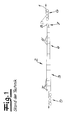
- Fig. 1 shows a known belt treatment apparatus for the continuous treatment of a metal strip, namely a thermal treatment.
- This device has a tempering 2, which is designed as a ribbon float furnace.
- the metal strip 1 passes through this strip float furnace 2 without contact by the strip between the upper nozzles and lower nozzles, which are acted upon by corresponding air pressure, is moved without contact. Details are not shown.
- the strip float furnace 2 has a heating section 3 on the inlet side and a cooling section 4 on the outlet side.
- the heating section is generally composed of a plurality of heating zones 3 ', while the cooling section is generally composed of a plurality of cooling zones 4', wherein the individual zones are individually or separately controllable.
- the heating of the metal strip is usually done by means of the air, so that the nozzles, z. B. the lower nozzles in addition to the support function can also take the temperature.
- the cooling zones the cooling is usually also done by air or by a combination of air and water.
- the target temperature in the heating zone is z. B. about 550 ° C to 570 ° C.
- the heating zones thus form heating and holding zones.
- the system on the inlet side has a tensioning roller set 5, with which the strip tension is reduced, for. B. on a specific strip tension of z. B. 0.5 to 1 MPa.
- the metal strip 1 is center-controlled by means of a belt position control device 7, ie the position of the metal strip is regulated in the strip running plane and transversely to the strip running direction.
- the strip tensioner with an outlet side pulley set 6 back to the usual line level of z. B. specifically increased 10 to 20 MPa. Because of the low specific strip tension within the strip float furnace, it is necessary to bring the metal strip 1 to the center of the strip by means of the strip position control device 7.
- the band position control device 7 is no longer located behind the temperature control 2 and therefore no longer behind the cooling section 4, but within the cooling section 4 itself.
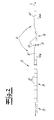
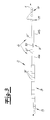
- the Fig. 2 and 3 again show a strip processing apparatus with a temperature control device 2, which has an inlet-side heating section 3 and a downstream cooling section 4.
- a tensioning roller set 5 is provided and on the outlet side, in turn, a further tensioning roller set 6 can be provided, which is only in Fig. 3 but not in Fig. 2 is shown.
- the heating section 3 is in turn composed of several heating zones 3 ', while the cooling section 4 is composed of a plurality of cooling zones 4'.
- the cooling section 4 is divided into two cooling section sections, namely a first cooling section 4a and a subsequent second cooling section 4b.
- the belt positioner device 7 is now arranged according to the invention between the first cooling section 4a and the second cooling section 4b.
- the metal strip is heated in the heating section 3 with the heating and holding zones 3 'in a basically known manner to the desired temperature and the temperature can be maintained for a desired time. Consequently, apart from an extension, the heating section 3 does not have to be modified compared with the prior art.
- the heating section 3 is then followed by the first cooling section 3a, with which the metal strip is cooled down in a first stage, preferably to a temperature of 100 ° C to 200 ° C, z. B 120 ° C to 150 ° C.
- the strip center is controlled by means of the strip center control device 7.
- this has a 90 ° control roller 8.
- this is followed in the exemplary embodiment Fig. 2 another tension roller set 9 to increase the tape tension.
- the band passes through the second cooling section 4b, so that it reaches the desired final temperature of z. B. 40 ° C to 60 ° C is cooled down. In this way, it is possible to increase the production capacity without appreciably prolonging the free tape length, so that an impermissible belt run in the furnace is avoided.
- the second cooling section 4b may be followed by another band position control device and / or another set of tensioning rollers. This is in Fig. 2 not shown.
- Fig. 3 shows a modified embodiment of the invention, in which the strip center control device 7 is designed as a three-roller belt center control with three rollers 10. Furthermore, in Fig. 3 indicated that behind the second cooling section 4b, a further strip center control device 11 and a further set of tension rollers 6 may be arranged.
- the additional midband control 11 behind the second cooling section 4b is therefore useful because in this embodiment between the cooling sections 4a, 4b no tensioning roller set is arranged and therefore also in the second section 4b is operated with a lower strip tension.
- the furnace zones 3 ', 4' in the embodiment according to the invention overall have a length which is greater than the length in the known embodiment according to Fig. 1 , Nevertheless, the free tape length is not greater, since the mid-band control 7 is already connected to the first cooling section 4a. This allows both the heating section 3 and the cooling section 4 over the prior art significantly extend. However, due to the division of the cooling section 4, cooling section sections 4a, 4b are formed which are each (significantly) shorter than the heating section 3.
Landscapes
- Chemical & Material Sciences (AREA)
- Engineering & Computer Science (AREA)
- Physics & Mathematics (AREA)
- Thermal Sciences (AREA)
- Crystallography & Structural Chemistry (AREA)
- Materials Engineering (AREA)
- Mechanical Engineering (AREA)
- Metallurgy (AREA)
- Organic Chemistry (AREA)
- Heat Treatment Of Strip Materials And Filament Materials (AREA)
- Registering, Tensioning, Guiding Webs, And Rollers Therefor (AREA)
- Tunnel Furnaces (AREA)
Description
Die Erfindung betrifft eine Vorrichtung zur kontinuierlichen Behandlung eines Metallbandes, insbesondere eines Metallbandes aus Aluminium (oder einer Aluminiumlegierung) oder aus Buntmetall (oder einer Buntmetalllegierung), mit zumindest einer Temperiervorrichtung, welche als Bandschwebeofen ausgebildet ist, durch den das Metallband schwebend hindurchgeführt wird und mit einer Bandlaufregeleinrichtung, mit der die Lage des Metallbandes in der Bandlaufebene und quer zur Bandlaufrichtung steuerbar oder regelbar ist, wobei der Bandschwebeofen zumindest eine einlaufseitige Heizstrecke und eine auslaufseitige Kühlstrecke aufweist. Das Metallband weist bevorzugt eine Dicke von 0,1 mm bis 6 mm auf.The invention relates to a device for the continuous treatment of a metal strip, in particular a metal strip of aluminum (or an aluminum alloy) or of non-ferrous metal (or a non-ferrous metal alloy), with at least one tempering, which is designed as a ribbon float furnace through which the metal strip is passed floating and with a strip running control device with which the position of the metal strip in the strip running plane and transverse to the strip running direction is controllable or controllable, wherein the strip float oven has at least one inlet side heating section and an outlet side cooling section. The metal strip preferably has a thickness of 0.1 mm to 6 mm.
Bei der Temperiervorrichtung handelt es sich um einen Bandschwebeofen, der eine Heizstrecke und eine Kühlstrecke aufweist. Die Heizstrecke besteht in der Regel aus mehreren Heizzonen (Aufheiz- bzw. Haltezonen) und die Kühlstrecke besteht in der Regel aus mehreren Kühlzonen. Das Metallband wird in einer solchen Temperiervorrichtung auf eine bestimmt (Soll-)Temperatur erwärmt, ggf. eine bestimmte Zeit bei dieser Temperatur gehalten und danach wieder abgekühlt. Der Durchlauf durch den Ofen erfolgt berührungslos, indem das Band zwischen Düsen (Luftdüsen), die mit entsprechendem Luftdruck beaufschlagt werden, geschwebt wird. Die Kühlung in den Kühlzonen kann durch Luft, Wasser oder eine Kombination von Luft und Wasser erfolgen. Solche Bandschwebeöfen mit Heizstrecke einerseits und Kühlstrecke andererseits sind bekannt (vgl. z. B.
Die
Bei einer solchen Vorrichtung der eingangs beschriebenen Art zur kontinuierlichen Behandlung eines Metallbandes mit einer Temperiervorrichtung bzw. mit einem Bandschwebeofen kann es sich z. B. um eine Glühlinie bzw. Kontiglühlinie handeln, in welcher das Metallband eine Wärmebehandlung aus metallurgischen Gründen erfährt, z. B. um bestimmte Festigkeits- und Verformungseigenschaften zu erzielen. Alternativ kann es sich bei der Vorrichtung aber auch um eine Bandbeschichtungsanlage bzw. eine Bandbeschichtungslinie handeln, in welcher die Wärmebehandlung des Metallbandes nicht im Sinne eines Glühens, sondern zur Trocknung einer Beschichtung eines Bandes erfolgt, so dass der Ofen dann als Durchlauftrockner ausgebildet ist.In such a device of the type described above for the continuous treatment of a metal strip with a tempering device or with a ribbon float oven, it may be, for. B. an annealing line or Kontiglühlinie act, in which the metal strip undergoes a heat treatment for metallurgical reasons, for. B. to achieve certain strength and deformation properties. Alternatively, however, the device may also be a strip coating line or a strip coating line in which the heat treatment of the metal strip does not take place in the sense of annealing, but for drying a coating of a strip, so that the oven is then designed as a continuous dryer.
Bei dem Metallband handelt es sich bevorzugt um Aluminium- oder Buntmetallband in einem Dickenbereich von 0,1 mm bis 6 mm.The metal strip is preferably aluminum or non-ferrous metal strip in a thickness range of 0.1 mm to 6 mm.
Da das Metallband z. B. in Glühlinien auf Temperaturen nahe des Schmelzpunktes erhitzt wird, ist es in der Regel erforderlich, innerhalb der Temperiervorrichtung einen verhältnismäßig geringen Bandzug einzustellen, um einen Bandriss zu vermeiden. Dazu wird der Bandzug z. B. einlaufseitig in einem Spannrollensatz abgebaut und auslaufseitig nach dem Abkühlen wieder in einem weiteren Spannrollensatz aufgebaut. In der Temperiervorrichtung (Bandschwebeofen) beträgt der spezifische Bandzug z. B. 0,5 bis 1 MPa. Da das Band insbesondere bei geringem Bandzug im Ofen "verlaufen" kann, z. B. aufgrund von etwaigem Bandsäbel, ist es erforderlich, das Band mithilfe einer Bandlageregeleinrichtung in geeigneter Weise zu positionieren, vorzugsweise auf Bandmitte zu bringen. Die Positionierung erfolgt folglich in der Bandlaufebene quer zur Bandlaufrichtung. Eine solche Bandlaufregeleinrichtung weist in der Regel zumindest eine Steuerrolle sowie geeignete Positionsmesseinrichtungen, z. B. Bandkantenerfassungen auf. Bei den aus der Praxis bekannten Anlagen ist die Bandlaufregeleinrichtung hinter der Temperiervorrichtung, d. h. nach der Kühlstrecke angeordnet. Die Steuerrolle ist in der Praxis üblicherweise als sogenannte PI-Bandmittenregelung ausgeführt, d. h. mit einem proportionalen P- und einem integralen I-Anteil. Der I-Anteil wirkt in die Ofensektion zurück und verhindert ein zu starkes Verlaufen des Bandes im Ofen. In der Regel sitzt die Steuerrolle auf einem beweglichen Grundrahmen. Dieser verdreht die Rolle um einen imaginären Drehpunkt bzw. um eine imaginäre Drehachse, die in der Ofensektion liegt und senkrecht auf die Bandlaufebene steht. Das Maß der Verschiebung der Rolle aus der Mittelachse der Ofensektion ist der proportionale Anteil, das Maß der Schiefstellung der Rolle der integrale Anteil der Bandmittenregelung. Bei einer schiefstehenden Rolle wandert das Band durch den sogenannten Wickeleffekt wieder in Richtung zur Bandmitte. Solche aus der Praxis bekannten Anlagen haben sich grundsätzlich bewährt.Since the metal strip z. B. is heated in annealing lines to temperatures near the melting point, it is usually necessary to adjust within the tempering a relatively low band tension to avoid a band break. For this purpose, the strip tension z. B. degraded on the inlet side in a clamping roller set and the outlet side after cooling again built in a further set of clamping rollers. In the tempering device (ribbon float furnace) the specific strip tension is z. B. 0.5 to 1 MPa. Since the tape can "run" in particular with low tape tension in the oven, z. B. due to eventual bandsaw, it is necessary to position the band by means of a belt position control device in a suitable manner, preferably to bring the center of the tape. The positioning is thus carried out in the strip running plane transversely to the strip running direction. Such a strip-guiding device generally has at least one control roller and suitable position-measuring devices, for. B. band edge detections on. In the systems known from practice, the strip running control device behind the tempering, that is arranged after the cooling section. The control role is usually carried out in practice as so-called PI band center control, ie with a proportional P and an integral I component. The I component acts in the furnace section back and prevents too much bleeding of the tape in the oven. As a rule, the control roller sits on a movable base frame. This rotates the roller about an imaginary pivot point or about an imaginary axis of rotation, which lies in the furnace section and is perpendicular to the strip running plane. The degree of displacement of the roller from the center axis of the furnace section is the proportional component, the extent of the misalignment of the roller the integral component of the belt center control. In an oblique role, the band wanders by the so-called winding effect back towards the center of the band. Such systems known from practice have basically proven themselves.
Eine Anlage der eingangs beschriebenen Art ist z. B. aus der
Im Übrigen ist aus der
In der Praxis besteht aufgrund der rasch wachsenden Nachfrage nach Karosseriebändern aus Aluminium der Bedarf, immer leistungsfähigere Kontiglühlinien zu errichten. Um höhere Produktionskapazitäten zu erreichen, durchläuft das Band die Behandlungssektion mit höherer Geschwindigkeit. Da jedoch pro Ofenzone nur ein begrenzter Wärmeeintrag ins Band gebracht werden kann, folgt daraus, dass die Temperiervorrichtung für eine höhere Produktionskapazität länger ausgelegt werden müsste. Da das Band wegen des geringen Bandzugs in der Ofensektion leichter verläuft, besteht bei großen Ofenlängen das Risiko, dass die bekannten Bandlageregeleinrichtungen nicht mehr ausreichen, um den Bandlauf im Ofen stabil zu halten, so dass die Gefahr besteht, dass das Band seitlich verläuft bzw. an der Ofenkonstruktion anläuft. Dieses kann zu unerwünschten Bandbeschädigungen oder einem Bandriss führen, so dass sich Anlagen mit erhöhter Produktionskapazität auf diese Weise nicht ohne Weiteres realisieren lassen. - Hier setzt die Erfindung ein.In practice, due to the rapidly growing demand for aluminum body manufacturers, there is a need to build more and more efficient annealing lines. To achieve higher production capacity, the belt passes through the treatment section at a higher speed. However, since only a limited heat input can be brought into the band per oven zone, it follows that the temperature control device would have to be designed longer for a higher production capacity. Because the band because of the If the low strip tension in the furnace section is easier, there is the risk with large furnace lengths that the known belt position control devices are no longer sufficient to keep the strip running in the furnace stable, so that there is a risk that the strip runs laterally or starts against the furnace construction. This can lead to undesired tape damage or a tape break, so that plants with increased production capacity can not be realized in this way easily. - This is where the invention starts.
Der Erfindung liegt die Aufgabe zugrunde, eine Vorrichtung zur kontinuierlichen Behandlung eines Metallbandes der eingangs beschriebenen Art zu schaffen, welche sich durch eine verbesserte Bandlageregelung auszeichnet und die insbesondere auch in langen Ofenstrecken einen einwandfreien Bandlauf garantiert.The invention has for its object to provide a device for the continuous treatment of a metal strip of the type described above, which is characterized by an improved band position control and guarantees a perfect tape especially in long kiln lines.
Zur Lösung dieser Aufgabe lehrt die Erfindung bei einer gattungsgemäßen Vorrichtung zur kontinuierlichen Behandlung eines Metallbandes, dass die Bandlageregeleinrichtung innerhalb der Kühlstrecke angeordnet ist. Die Kühlstrecke ist dazu bevorzugt in zumindest einen ersten Kühlstreckenabschnitt und einen nachfolgenden beabstandeten zweiten Kühlstreckenabschnitt aufgeteilt, wobei die Bandlageregeleinrichtung zwischen dem ersten Kühlstreckenabschnitt und dem zweiten Kühlstreckenabschnitt angeordnet ist. Erfindungsgemäß ist die Bandlageregeleinrichtung folglich nicht mehr ausgangsseitig hinter der Temperiervorrichtung und folglich nicht mehr nach der letzten Kühlzone angeordnet, sondern sie wird gleichsam in die Kühlstrecke integriert, indem diese bevorzugt in zwei Kühlstreckenabschnitte aufgeteilt wird. In einem ersten Abschnitt wird das Band soweit heruntergekühlt, dass es problemlos die Bandlageregeleinrichtung passieren kann. Im Anschluss an den ersten Kühlstreckenabschnitt befindet sich folglich die Bandlageregeleinrichtung. Anschließend durchläuft das Band den zweiten Kühlstreckenabschnitt und folglich den zweiten Teil der Kühlzonen, so dass das Band anschließend auf die gewünschte Endtemperatur heruntergekühlt wird. Auf diese Weise kann insgesamt mit einer langen Ofenstrecke und folglich mit langen Heizstrecken und Kühlstrecken gearbeitet werden, so dass die Produktionskapazität erhöht wird, ohne dass die freie Bandlänge im Bereich niedrigen Bandzuges nennenswert erhöht werden muss. Auf diese Weise wird ein unzulässiger Bandverlauf im Ofen zuverlässig vermieden.To solve this problem, the invention teaches in a generic device for the continuous treatment of a metal strip, that the band position control device is disposed within the cooling section. For this purpose, the cooling section is preferably divided into at least one first cooling section section and a subsequent spaced second cooling section section, wherein the band position control device is arranged between the first cooling section section and the second cooling section section. According to the invention, the band position control device is consequently no longer arranged on the output side behind the temperature control device and consequently no longer after the last cooling zone, but rather it is integrated into the cooling path, as it is preferably divided into two cooling path sections. In a first section, the belt is cooled down so far that it can easily pass through the belt control device. Following the first cooling section, therefore, the band position control device is located. Subsequently, the band passes through the second cooling section and thus the second part of the Cooling zones, so that the band is then cooled down to the desired final temperature. In this way, a total of a long kiln line and consequently with long heating sections and cooling sections can be used, so that the production capacity is increased, without the free band length must be increased significantly in the range of low strip tension. In this way, an impermissible belt run in the oven is reliably avoided.
Die Bandlageregeleinrichtung selbst kann in herkömmlicher Weise ausgebildet sein, es kann folglich auf herkömmliche Lösungen zurückgegriffen werden. Erfindungsgemäß kommt es auf die besondere Positionierung der Bandlaufregelvorrichtung innerhalb der Ofensektion bzw. der innerhalb der Kühlstrecke an.The tape position control device itself can be designed in a conventional manner, it can therefore be resorted to conventional solutions. According to the invention, it depends on the particular positioning of the strip running control device within the furnace section or within the cooling section.
So kann die Bandlageregeleinrichtung für die Bandlageregelung z. B. eine herkömmliche, verstellbare Umlenkrolle, z. B. eine 90°-Umlenkrolle aufweisen bzw. als solche ausgebildet sein. Es empfiehlt sich jedoch, die Umlenkrolle mit einer geeigneten (hoch-)temperaturbeständigen Beschichtung zu versehen, da die Bandtemperatur zwischen der ersten Kühlstrecke und der zweiten Kühlstrecke bevorzugt 100 °C bis 200 °C, besonders bevorzugt 120 °C bis 150 °C beträgt. Alternativ zu einer 90°-Steuerrolle kann auch auf eine andere bekannte Art der Bandmittenregelung, z. B. mithilfe einer Mehrrollensteuereinrichtung, z. B. einer Drei-Rollen-Regeleinrichtung oder eines Steuertreibers (z. B. als Rollenpaar) gearbeitet werden. Auch in diesem Fall werden bevorzugt geeignete Beschichtungen vorgesehen. Vorzugsweise wird die Bandlageregelung bzw. Bandmittenregelung in grundsätzlich bekannter Weise als PI-Regelung ausgeführt. Die Steuerrolle bzw. die Mehrrollenanordnung sitzt folglich in grundsätzlich bekannter Weise auf einen beweglichen Grundrahmen. Dieser verdreht die Rolle bzw. die Rollen um einen imaginären Drehpunkt, der wiederum in der Ofensektion liegt. Das Maß der Verschiebung der Rolle aus der Mittelachse der Ofensektion ist der proportionale Anteil, das Maß der Schiefstellung der Rolle der integrale Anteil der Bandmittenregelung.Thus, the band position control device for the band position control z. As a conventional, adjustable pulley, z. B. have a 90 ° -Umlenkrolle or be designed as such. However, it is advisable to provide the deflection roller with a suitable (high) temperature-resistant coating, since the belt temperature between the first cooling section and the second cooling section is preferably 100 ° C to 200 ° C, particularly preferably 120 ° C to 150 ° C. As an alternative to a 90 ° control roller can also be on another known type of band center control, z. B. using a multi-role control device, for. B. a three-roller control device or a control driver (eg., As a pair of rollers) are worked. Also in this case, suitable coatings are preferably provided. Preferably, the band position control or band center control is performed in a basically known manner as a PI control. The control roller or the multi-roller assembly thus sits in a basically known manner on a movable base frame. This twists the role or the roles around an imaginary fulcrum, which in turn in the Furnace section is located. The degree of displacement of the roller from the center axis of the furnace section is the proportional component, the extent of the misalignment of the roller the integral component of the belt center control.
Alternativ kann die Bandlageregeleinrichtung als berührungslos arbeitende Bandlageregeleinrichtung ausgebildet sein. Dazu kann die Bandmittenregelung z. B. berührungslos über Linearmotoren erfolgen. Hier kann grundsätzlich auf bekannte Anordnungen zur Beeinflussung des Metallbandes mithilfe von Linearmotoren zurückgegriffen werden, die beispielsweise in der
Bevorzugt weist die Bandbehandlungsanlage einlaufseitig einen ersten Spannrollensatz auf, der vor der Temperiervorrichtung angeordnet ist, um den Bandzug herabzusetzen. Ferner ist es zweckmäßig, ausgangsseitig und folglich hinter der Temperiervorrichtung einen weiteren Spannrollensatz vorzusehen, mit dem der Bandzug wieder erhöht wird, so dass sich weitere Prozessschritte anschließen können, wie z. B. das Streckrichten, Reinigen oder Kantenbesäumen.Preferably, the belt treatment plant on the inlet side on a first set of tension rollers, which is arranged in front of the temperature control to reduce the strip tension. Furthermore, it is expedient to provide on the output side and thus behind the tempering a further set of tension rollers, with which the strip tension is increased again, so that can join further process steps, such as. B. straightening, cleaning or edge trimming.
Optional liegt es im Rahmen der Erfindung, dass zwischen dem ersten Kühlstreckenabschnitt und dem zweiten Kühlstreckenabschnitt hinter der Bandlageregeleinrichtung ein (weiterer) Spannrollensatz angeordnet ist, um den Bandzug bereits an dieser Stelle zu erhöhen. Dieses hat den Vorteil, dass das Band den zweiten Teil der Kühlzonen mit einem etwas erhöhten Bandzug durchlaufen kann. Auch in diesem Fall ist es zweckmäßig, die Rollen eines solchen Rollensatzes mit entsprechenden temperaturbeständigen Beschichtungen zu versehen. Erfindungsgemäß kommt es darauf an, dass zwischen dem ersten Kühlstreckenabschnitt und dem zweiten Kühlstreckenabschnitt eine Bandlageregelung erfolgt. Optional kann es zweckmäßig sein, hinter dem zweiten Kühlstreckenabschnitt eine weitere Bandlageregelung vorzusehen. Dieses kann insbesondere dann zweckmäßig sein, wenn zwischen dem ersten Kühlstreckenabschnitt und dem zweiten Kühlstreckenabschnitt kein zusätzlicher Spannrollensatz vorgesehen ist und folglich auch im zweiten Kühlstreckenabschnitt mit niedrigerem Bandzug gearbeitet wird. Sofern zwischen den beiden Kühlstreckenabschnitten ein Spannrollensatz vorgesehen ist und folglich der Bandzug bereits an dieser Stelle erhöht wird, kann hinter dem zweiten Kühlstreckenabschnitt eventuell auf eine zweite Bandlageregelung verzichtet werden.Optionally, it is within the scope of the invention that a (further) tensioning roller set is arranged between the first cooling section section and the second cooling section section behind the belt position control device in order to increase the belt tension already at this point. This has the advantage that the band can pass through the second part of the cooling zones with a slightly increased strip tension. Also in this case it is expedient to provide the rollers of such a roller set with appropriate temperature-resistant coatings. According to the invention, it is important that a band position control takes place between the first cooling section section and the second cooling section section. Optionally, it may be appropriate to behind the second cooling section section to provide a further band position control. This may be particularly useful if between the first cooling section and the second cooling section section no additional tensioning roller set is provided and consequently also worked in the second cooling section section with a lower strip tension. If a tensioning roller set is provided between the two cooling sections and consequently the strip tension is already increased at this point, it may be possible to dispense with a second strip position control behind the second cooling section.
Die Aufteilung der Kühlstrecke in zwei Kühlstreckenabschnitte hat zur Folge, dass die beiden Kühlstreckenabschnitte (deutlich) kürzer sind als ein entsprechender einheitlicher Kühlstreckenabschnitt. Gegenüber herkömmlichen Anlagen kann auf diese Weise die gesamte Temperiervorrichtung verlängert werden, d. h. sowohl die Heizstrecke kann verlängert werden als auch die gesamte Kühlstrecke.The division of the cooling section into two cooling sections has the consequence that the two cooling sections are (significantly) shorter than a corresponding uniform cooling section. Compared to conventional systems can be extended in this way, the entire tempering, d. H. Both the heating section can be extended and the entire cooling section.
Gegenstand der Erfindung ist auch ein Verfahren zur kontinuierlichen Behandlung eines Metallbandes mit einer Vorrichtung der beschriebenen Art, wobei das Metallband zur thermischen Behandlung schwebend durch die Heizstrecke und die Kühlstrecke geführt wird. Dieses Verfahren ist dadurch gekennzeichnet, dass die Lage des Metallbandes (innerhalb der Bandlaufebene und quer zur Bandlaufrichtung) mit einer innerhalb der Kühlstrecke angeordneten Bandlageregeleinrichtung gesteuert oder geregelt wird.The invention also provides a process for the continuous treatment of a metal strip with a device of the type described, wherein the metal strip for thermal treatment is guided floating through the heating section and the cooling section. This method is characterized in that the position of the metal strip (within the strip running plane and transversely to the strip running direction) is controlled or regulated by means of a strip position control device arranged inside the cooling section.
Wie bereits beschrieben ist eine solche Bandlageregeleinrichtung bevorzugt mit geeigneten Messeinrichtungen und einer Rückführung ausgestattet, so dass eine echte Regelung der Bandlage erfolgt. Grundsätzlich sind von der Erfindung aber auch Ausführungsformen erfasst, bei denen ohne Messung und/oder ohne Rückführung gearbeitet wird, so dass keine Regelung der Bandlage, sondern lediglich eine Steuerung erfolgt.As already described, such a band position control device is preferably equipped with suitable measuring devices and a feedback, so that a real regulation of the band position takes place. In principle, however, the invention also covers embodiments in which without measurement and / or without Return is worked so that no regulation of the band position, but only a control is done.
Bevorzugt wird die Länge des ersten Kühlstreckenabschnittes so bemessen, dass das Metallband zwischen dem ersten Kühlstreckenabschnitt und dem zweiten Kühlstreckenabschnitt und folglich im Bereich der Bandlageregeleinrichtung eine Temperatur von bis zum 200 °C, z. B. 100 °C bis 200 °C aufweist. Besonders bevorzugt beträgt die Temperatur bis zu 150 °C, z. B. 120 °C bis 150 °C. Die Länge des zweiten Kühlstreckenabschnittes kann dann z. B. so bemessen sein, dass das Band mit einer Temperatur von bis zu 70°, vorzugsweise bis zu 60° C z. B. 40 °C bis 60 °C ausläuft, so dass problemlos weitere Prozessschritte, wie z. B. Streckrichten, Reinigen oder Kantenbesäumen folgen können.Preferably, the length of the first cooling section is dimensioned such that the metal strip between the first cooling section and the second cooling section and thus in the region of the band position control device a temperature of up to 200 ° C, z. B. 100 ° C to 200 ° C. More preferably, the temperature is up to 150 ° C, z. B. 120 ° C to 150 ° C. The length of the second cooling section can then z. B. be sized so that the tape with a temperature of up to 70 °, preferably up to 60 ° C z. B. 40 ° C to 60 ° C, so that easily further process steps, such. B. straightening, cleaning or edge trimming can follow.
Die erfindungsgemäße Anlage kann z. B. als Glühlinie ausgebildet sein oder Bestandteil einer Glühlinie sein. Die Temperiervorrichtung ist dann als Glühofen ausgebildet. Alternativ kann die Anlage als Bandbeschichtungsanlage ausgebildet sein oder Bestandteil einer Bandbeschichtungsanlage sein. Die Temperiervorrichtung ist dann als Trockner bzw. Trocknerofen ausgebildet. In beiden Fällen sind die Öfen/Trockner bevorzugt als Bandschwebeofen ausgebildet.The inventive system can, for. B. be designed as annealing line or be part of an annealing line. The tempering device is then designed as an annealing furnace. Alternatively, the system can be designed as a coil coating system or be part of a coil coating plant. The tempering device is then designed as a dryer or dryer oven. In both cases, the ovens / dryers are preferably designed as a ribbon float oven.
Im Folgenden wird die Erfindung anhand von lediglich Ausführungsbeispielen darstellenden Zeichnungen näher erläutert. Es zeigen
- Fig. 1
- eine bekannte Bandbehandlungsvorrichtung nach dem Stand der Technik in einer vereinfachten schematischen Darstellung,
- Fig. 2
- eine erfindungsgemäße Bandbehandlungsvorrichtung in einer vereinfachten schematischen Darstellung und
- Fig. 3
- eine abgewandelte Ausführungsform des Gegenstandes nach
Fig. 2 .
- Fig. 1
- a known prior art belt treatment apparatus in a simplified schematic representation,
- Fig. 2
- a strip treatment device according to the invention in a simplified schematic representation and
- Fig. 3
- a modified embodiment of the article according to
Fig. 2 ,
Um den Erfindungsgedanken zu verdeutlichen, ist es zweckmäßig, zunächst nochmals den Stand der Technik gemäß
Will man die Produktionskapazität einer solchen in
Erfindungsgemäß wird daher die Bandlageregeleinrichtung 7 nicht mehr hinter der Temperiervorrichtung 2 und folglich nicht mehr hinter der Kühlstrecke 4 angeordnet, sondern innerhalb der Kühlstrecke 4 selbst. Dieses wird anhand der
Vergleicht man z. B. die
Claims (12)
- Device for continuous processing of a metal strip (1), particularly a metal strip made of aluminium or an aluminium alloy, or of non-ferrous metal or a non-ferrous metal alloy,
having at least one thermal treatment apparatus, which is in the form of a strip flotation furnace (2) through which the metal strip (1) is floated,
and having a strip position adjustment device (7), with which the position of the metal strip (1) can be controlled or adjusted in the strip running plane and transversely to the direction of advance of the strip,
wherein the strip flotation furnace (1) has at least one heating line (3) on the infeed side and one cooling line (4) on the outfeed side,
characterised in that
the strip position adjustment device (7) is arranged in the cooling line (4). - Device according to claim 1, characterised in that the cooling line (4) is divided into at least a first cooling line section (4a) and a second cooling line section (4b) downstream therefrom, wherein the strip position adjustment device (7) is arranged between the first cooling line section (4a) and the second cooling line section (4b).
- Device according to either of claims 1 or 2, characterised in that a further strip position adjustment device (11) is arranged after the second cooling line section.
- Device according to any one of claims 1 to 3, characterised in that the strip position adjustment device (7, 11) comprises a movable deflection roller (8), for example a 90° deflection roller, or has the form of such for adjusting the position of the strip.
- Device according to any one of claims 1 to 3, characterised in that the strip position adjustment device (7, 11) is in the form of a multi-roller assembly, for example a three-roller device.
- Device according to any one of claims 1 to 5, characterised in that the strip position adjustment device (7, 11) is designed as a device that functions without contact, for example with linear motors.
- Device according to any one of claims 1 to 6, characterised in that a tension roller assembly (11) located downstream from the strip position adjustment device (7) is arranged between the first cooling line section (4a) the second cooling line section (4b).
- Device according to any one of claims 1 to 7, characterised in that the rollers (8, 9) of the strip position adjustment device (7) and/or of the tension roller assembly (11) are furnished with a thermally resistant coating.
- Method for continuous processing of a metal strip using a device according to any one of claims 1 to 8, wherein the metal strip is passed in floating manner through the heating line and the cooling line to undergo thermal processing, characterised in that the position of the metal strip is controlled or adjusted with a strip position adjustment device arranged in the cooling line.
- Method according to claim 9, characterised in that the strip position adjustment device is arranged between a first cooling line section and a second cooling line section.
- Method according to either of claims 9 or 10, characterised in that strip position is adjusted with a PI control having a proportional P-component and an integral I-component.
- Method according to any one of claims 9 to 11, characterised in that the strip position adjustment device is arranged in an area of the cooling line, for example between the first cooling line section and the second cooling line section, in which the temperature of the metal strip reaches up to 200°C, for example 100°C to 200°C, preferably up to 150°C, for example 120°C to 150°C.
Priority Applications (1)
| Application Number | Priority Date | Filing Date | Title |
|---|---|---|---|
| PL13183368T PL2722112T3 (en) | 2012-10-19 | 2013-09-06 | Method and device for continuous treatment of a metal strip |
Applications Claiming Priority (1)
| Application Number | Priority Date | Filing Date | Title |
|---|---|---|---|
| DE102012110010.1A DE102012110010B4 (en) | 2012-10-19 | 2012-10-19 | Apparatus and method for the continuous treatment of a metal strip |
Publications (3)
| Publication Number | Publication Date |
|---|---|
| EP2722112A1 EP2722112A1 (en) | 2014-04-23 |
| EP2722112B1 true EP2722112B1 (en) | 2015-06-24 |
| EP2722112B2 EP2722112B2 (en) | 2025-03-26 |
Family
ID=49170558
Family Applications (1)
| Application Number | Title | Priority Date | Filing Date |
|---|---|---|---|
| EP13183368.3A Active EP2722112B2 (en) | 2012-10-19 | 2013-09-06 | Method and device for continuous treatment of a metal strip |
Country Status (10)
| Country | Link |
|---|---|
| US (1) | US10415113B2 (en) |
| EP (1) | EP2722112B2 (en) |
| KR (1) | KR102162942B1 (en) |
| CN (1) | CN103773943B (en) |
| CA (1) | CA2829532C (en) |
| DE (1) | DE102012110010B4 (en) |
| ES (1) | ES2543328T3 (en) |
| HU (1) | HUE025366T2 (en) |
| PL (1) | PL2722112T3 (en) |
| RU (1) | RU2623520C2 (en) |
Families Citing this family (8)
| Publication number | Priority date | Publication date | Assignee | Title |
|---|---|---|---|---|
| DE102012110010B4 (en) * | 2012-10-19 | 2016-09-01 | Bwg Bergwerk- Und Walzwerk-Maschinenbau Gmbh | Apparatus and method for the continuous treatment of a metal strip |
| FR3027920B1 (en) * | 2014-10-29 | 2019-03-29 | Fives Stein | METHOD FOR ORIENTING STEEL SHEET GRAINS, DEVICE THEREFOR, AND INSTALLATION USING SAID METHOD OR DEVICE |
| DE102014118946B4 (en) | 2014-12-18 | 2018-12-20 | Bwg Bergwerk- Und Walzwerk-Maschinenbau Gmbh | Apparatus and method for the continuous treatment of a metal strip |
| CN104831053B (en) * | 2015-05-25 | 2017-08-22 | 马钢(集团)控股有限公司 | A kind of electrical sheet annealing heating method for supporting |
| KR102094940B1 (en) | 2015-06-09 | 2020-03-30 | 노벨리스 인크. | Non-contact self-pilot |
| CN108603241A (en) * | 2016-01-29 | 2018-09-28 | 康宁股份有限公司 | Heat-treated metal material and correlation technique |
| DE102016102093B3 (en) * | 2016-02-05 | 2017-06-14 | Bwg Bergwerk- Und Walzwerk-Maschinenbau Gmbh | Continuous cooling device and method for cooling a metal strip |
| DE102018100842B3 (en) | 2018-01-16 | 2019-05-09 | Ebner Industrieofenbau Gmbh | Continuous furnace for aluminum strips |
Citations (13)
| Publication number | Priority date | Publication date | Assignee | Title |
|---|---|---|---|---|
| US4218002A (en) | 1979-05-31 | 1980-08-19 | Olin Corporation | Strip material center guide assembly |
| EP0068272A1 (en) | 1981-06-15 | 1983-01-05 | Daidotokushuko Kabushiki Kaisha | Apparatus for conveying strip material |
| JPS5848641A (en) | 1981-09-16 | 1983-03-22 | Daido Steel Co Ltd | Continuous heat treating furnace |
| EP0117896A2 (en) | 1983-03-03 | 1984-09-12 | Elektro-Mechanik Gmbh | Guide device for the edges or the middle of a web |
| US5431755A (en) | 1993-04-24 | 1995-07-11 | Vits Maschinenbau Gmbh | Method of and arrangement for thermal treatment of continuously moving metal bands |
| US5472528A (en) | 1992-03-19 | 1995-12-05 | Stein Heurtey | Heat-treatment method for metal strips |
| US5798007A (en) | 1996-03-13 | 1998-08-25 | Stein Heurtey | Process and apparatus for the continuous heat treatment of a metal strip travelling in a different atmosphere |
| US5964114A (en) | 1997-05-13 | 1999-10-12 | Bwg Bergwerk- Und Walzwerk- Maschinenbau Gmbh | Method of regulating the stress distribution in metal strips or sheet, especially of nonferromagnetic metals |
| US6413470B1 (en) | 1998-02-03 | 2002-07-02 | Carl Kramer | Device for guiding bands in a suspended manner |
| EP1443120A1 (en) | 2003-01-28 | 2004-08-04 | Carl Prof.Dr.-Ing. Kramer | Device for continuous heat treatment of metal strips |
| DE10326071A1 (en) | 2003-06-10 | 2005-01-13 | Kramer, Carl, Prof. Dr.-Ing. | Deviating device for metallic strips is formed by a number of rollers arranged so that a strip running over the rollers take on a circular contour |
| DE10337502B4 (en) | 2003-08-14 | 2006-03-30 | Kramer, Carl, Prof. Dr.-Ing. | Method for operating a continuous heat treatment plant for webs and belts with predominantly convective heat transfer |
| US20100175452A1 (en) | 2007-06-22 | 2010-07-15 | Joachim Ohlert | Method for hot rolling and for heat treatment of a steel strip |
Family Cites Families (13)
| Publication number | Priority date | Publication date | Assignee | Title |
|---|---|---|---|---|
| JPS6270527A (en) * | 1985-09-25 | 1987-04-01 | Mitsubishi Heavy Ind Ltd | Continuous annealing furnace for metal strip |
| JPS62235429A (en) * | 1986-04-04 | 1987-10-15 | Daido Steel Co Ltd | Centering device for metal strip material in floating heat treatment furnace |
| JP3489240B2 (en) * | 1995-01-13 | 2004-01-19 | 大同特殊鋼株式会社 | Floating furnace |
| US5648539A (en) | 1996-02-29 | 1997-07-15 | Xerox Corporation | Low temperature arylamine processes |
| EP1008661A3 (en) | 1998-12-12 | 2000-06-28 | Sundwig GmbH | Installation for treating a continuously conveyed metal strip along a principal direction of transportation |
| FR2796139B1 (en) | 1999-07-06 | 2001-11-09 | Stein Heurtey | METHOD AND DEVICE FOR SUPPRESSING THE VIBRATION OF STRIPS IN GAS BLOWING ZONES, ESPECIALLY COOLING ZONES |
| DE10163070A1 (en) * | 2001-12-20 | 2003-07-03 | Sms Demag Ag | Method and device for the controlled straightening and cooling of wide metal strip, in particular steel strip or sheet metal, emerging from a hot strip rolling mill |
| FR2897620B1 (en) | 2006-02-21 | 2008-04-04 | Stein Heurtey | METHOD AND DEVICE FOR COOLING AND STABILIZING BAND IN A CONTINUOUS LINE |
| FI121309B (en) | 2006-06-01 | 2010-09-30 | Outokumpu Oy | A way to control the metal strip in the heat treatment furnace |
| CN102137943B (en) * | 2009-04-22 | 2013-01-09 | 新日铁工程技术株式会社 | Cold-rolled steel sheet production method and production facility |
| EP2468905A1 (en) | 2010-12-22 | 2012-06-27 | Siemens VAI Metals Technologies GmbH | Cooling section with integrated vertical belt storage |
| CN202072725U (en) * | 2011-05-03 | 2011-12-14 | 佛山市高明基业冷轧钢板有限公司 | Composite unit with functions of producing annealing plate and electrical steel |
| DE102012110010B4 (en) * | 2012-10-19 | 2016-09-01 | Bwg Bergwerk- Und Walzwerk-Maschinenbau Gmbh | Apparatus and method for the continuous treatment of a metal strip |
-
2012
- 2012-10-19 DE DE102012110010.1A patent/DE102012110010B4/en not_active Revoked
-
2013
- 2013-09-06 EP EP13183368.3A patent/EP2722112B2/en active Active
- 2013-09-06 HU HUE13183368A patent/HUE025366T2/en unknown
- 2013-09-06 PL PL13183368T patent/PL2722112T3/en unknown
- 2013-09-06 ES ES13183368.3T patent/ES2543328T3/en active Active
- 2013-10-08 CA CA2829532A patent/CA2829532C/en active Active
- 2013-10-16 KR KR1020130123296A patent/KR102162942B1/en active Active
- 2013-10-17 US US14/056,372 patent/US10415113B2/en active Active
- 2013-10-18 RU RU2013146678A patent/RU2623520C2/en active
- 2013-10-18 CN CN201310489275.1A patent/CN103773943B/en not_active Expired - Fee Related
Patent Citations (13)
| Publication number | Priority date | Publication date | Assignee | Title |
|---|---|---|---|---|
| US4218002A (en) | 1979-05-31 | 1980-08-19 | Olin Corporation | Strip material center guide assembly |
| EP0068272A1 (en) | 1981-06-15 | 1983-01-05 | Daidotokushuko Kabushiki Kaisha | Apparatus for conveying strip material |
| JPS5848641A (en) | 1981-09-16 | 1983-03-22 | Daido Steel Co Ltd | Continuous heat treating furnace |
| EP0117896A2 (en) | 1983-03-03 | 1984-09-12 | Elektro-Mechanik Gmbh | Guide device for the edges or the middle of a web |
| US5472528A (en) | 1992-03-19 | 1995-12-05 | Stein Heurtey | Heat-treatment method for metal strips |
| US5431755A (en) | 1993-04-24 | 1995-07-11 | Vits Maschinenbau Gmbh | Method of and arrangement for thermal treatment of continuously moving metal bands |
| US5798007A (en) | 1996-03-13 | 1998-08-25 | Stein Heurtey | Process and apparatus for the continuous heat treatment of a metal strip travelling in a different atmosphere |
| US5964114A (en) | 1997-05-13 | 1999-10-12 | Bwg Bergwerk- Und Walzwerk- Maschinenbau Gmbh | Method of regulating the stress distribution in metal strips or sheet, especially of nonferromagnetic metals |
| US6413470B1 (en) | 1998-02-03 | 2002-07-02 | Carl Kramer | Device for guiding bands in a suspended manner |
| EP1443120A1 (en) | 2003-01-28 | 2004-08-04 | Carl Prof.Dr.-Ing. Kramer | Device for continuous heat treatment of metal strips |
| DE10326071A1 (en) | 2003-06-10 | 2005-01-13 | Kramer, Carl, Prof. Dr.-Ing. | Deviating device for metallic strips is formed by a number of rollers arranged so that a strip running over the rollers take on a circular contour |
| DE10337502B4 (en) | 2003-08-14 | 2006-03-30 | Kramer, Carl, Prof. Dr.-Ing. | Method for operating a continuous heat treatment plant for webs and belts with predominantly convective heat transfer |
| US20100175452A1 (en) | 2007-06-22 | 2010-07-15 | Joachim Ohlert | Method for hot rolling and for heat treatment of a steel strip |
Non-Patent Citations (2)
| Title |
|---|
| M IMOSE: "Heating and Cooling Technology in the Continuous Annealing", TRANSACTIONS ISIJ, 1985, XP055276436 |
| PROF. DR.-ING . C. KRAMER: "Continuous heat treatment of floatingly guided copper alloy strips", HEAT PROCESSING, June 2003 (2003-06-01), XP055276421 |
Also Published As
| Publication number | Publication date |
|---|---|
| KR102162942B1 (en) | 2020-10-07 |
| CN103773943B (en) | 2018-02-06 |
| PL2722112T3 (en) | 2015-11-30 |
| DE102012110010A1 (en) | 2014-04-24 |
| DE102012110010B4 (en) | 2016-09-01 |
| US10415113B2 (en) | 2019-09-17 |
| ES2543328T3 (en) | 2015-08-18 |
| CN103773943A (en) | 2014-05-07 |
| US20140110890A1 (en) | 2014-04-24 |
| RU2013146678A (en) | 2015-04-27 |
| HUE025366T2 (en) | 2016-02-29 |
| CA2829532C (en) | 2020-03-10 |
| CA2829532A1 (en) | 2014-04-19 |
| EP2722112A1 (en) | 2014-04-23 |
| RU2623520C2 (en) | 2017-06-27 |
| EP2722112B2 (en) | 2025-03-26 |
| KR20140050552A (en) | 2014-04-29 |
Similar Documents
| Publication | Publication Date | Title |
|---|---|---|
| EP2722112B1 (en) | Method and device for continuous treatment of a metal strip | |
| EP3234204B1 (en) | Device and method for continous treatment of a metal strip | |
| EP3328566B1 (en) | Method and device for changing the temperature of metal strips in a flatness-adaptive manner | |
| EP1955786A1 (en) | Device and method for levelling metal strips | |
| EP3350352A1 (en) | Continuous flow cooling device and method for cooling a metal strip | |
| DE10163070A1 (en) | Method and device for the controlled straightening and cooling of wide metal strip, in particular steel strip or sheet metal, emerging from a hot strip rolling mill | |
| DE2363223C3 (en) | Device for continuous heating in a tower furnace | |
| WO2010127820A1 (en) | Spray bar, path and method for applying a medium onto a product | |
| DE19840898A1 (en) | Process for producing load-optimized steel strips | |
| DE2723720A1 (en) | DEVICE FOR MAINTAINING A CERTAIN TENSION EXERCISED ON A METAL STRAP DURING A DIRECTIONAL PROCESS | |
| EP0422056B1 (en) | Process and installation for manufacturing a metal strip having a thickness less than or equal to 10 mm | |
| WO2006050680A1 (en) | Method and device for shaping wire-shaped and rod-shaped starting materials close to the gauge block, and correspondingly produced flat profiled element | |
| EP3201369B1 (en) | Method for the manufacture of steel strip material having different mechanical properties across the width of the strip | |
| DE102005047432A1 (en) | Plate glass heat treatment oven has ceramic rollers and comparative heat sensors | |
| WO2006027238A1 (en) | Method and device for milling a metal strip | |
| EP3307448B1 (en) | Method and device for controlling a parameter of a rolled stock | |
| EP3573772B1 (en) | Casting rolling line and method for treating a workpiece with same | |
| DE102008008648B3 (en) | Device for cooling a workpiece | |
| DE102016000576A1 (en) | Method for the continuous annealing and quenching of strips of metallic materials and apparatus for carrying out the method | |
| DE102017112424A1 (en) | Apparatus and method for strip position control | |
| DE202013101451U1 (en) | Apparatus for treating a fibrous web |
Legal Events
| Date | Code | Title | Description |
|---|---|---|---|
| PUAI | Public reference made under article 153(3) epc to a published international application that has entered the european phase |
Free format text: ORIGINAL CODE: 0009012 |
|
| AK | Designated contracting states |
Kind code of ref document: A1 Designated state(s): AL AT BE BG CH CY CZ DE DK EE ES FI FR GB GR HR HU IE IS IT LI LT LU LV MC MK MT NL NO PL PT RO RS SE SI SK SM TR |
|
| AX | Request for extension of the european patent |
Extension state: BA ME |
|
| 17P | Request for examination filed |
Effective date: 20140326 |
|
| RBV | Designated contracting states (corrected) |
Designated state(s): AL AT BE BG CH CY CZ DE DK EE ES FI FR GB GR HR HU IE IS IT LI LT LU LV MC MK MT NL NO PL PT RO RS SE SI SK SM TR |
|
| REG | Reference to a national code |
Ref country code: DE Ref legal event code: R079 Ref document number: 502013000776 Country of ref document: DE Free format text: PREVIOUS MAIN CLASS: B21B0039000000 Ipc: C21D0009560000 |
|
| GRAP | Despatch of communication of intention to grant a patent |
Free format text: ORIGINAL CODE: EPIDOSNIGR1 |
|
| RIC1 | Information provided on ipc code assigned before grant |
Ipc: C21D 11/00 20060101ALI20150211BHEP Ipc: B21B 39/00 20060101ALI20150211BHEP Ipc: C21D 9/54 20060101ALI20150211BHEP Ipc: C21D 9/63 20060101ALI20150211BHEP Ipc: C21D 9/56 20060101AFI20150211BHEP |
|
| INTG | Intention to grant announced |
Effective date: 20150309 |
|
| GRAS | Grant fee paid |
Free format text: ORIGINAL CODE: EPIDOSNIGR3 |
|
| GRAA | (expected) grant |
Free format text: ORIGINAL CODE: 0009210 |
|
| AK | Designated contracting states |
Kind code of ref document: B1 Designated state(s): AL AT BE BG CH CY CZ DE DK EE ES FI FR GB GR HR HU IE IS IT LI LT LU LV MC MK MT NL NO PL PT RO RS SE SI SK SM TR |
|
| REG | Reference to a national code |
Ref country code: GB Ref legal event code: FG4D Free format text: NOT ENGLISH |
|
| REG | Reference to a national code |
Ref country code: CH Ref legal event code: EP |
|
| REG | Reference to a national code |
Ref country code: AT Ref legal event code: REF Ref document number: 732917 Country of ref document: AT Kind code of ref document: T Effective date: 20150715 |
|
| REG | Reference to a national code |
Ref country code: IE Ref legal event code: FG4D Free format text: LANGUAGE OF EP DOCUMENT: GERMAN |
|
| REG | Reference to a national code |
Ref country code: DE Ref legal event code: R096 Ref document number: 502013000776 Country of ref document: DE |
|
| REG | Reference to a national code |
Ref country code: SE Ref legal event code: TRGR |
|
| REG | Reference to a national code |
Ref country code: ES Ref legal event code: FG2A Ref document number: 2543328 Country of ref document: ES Kind code of ref document: T3 Effective date: 20150818 |
|
| REG | Reference to a national code |
Ref country code: FR Ref legal event code: PLFP Year of fee payment: 3 |
|
| RAP2 | Party data changed (patent owner data changed or rights of a patent transferred) |
Owner name: BWG BERGWERK- UND WALZWERK-MASCHINENBAU GMBH |
|
| REG | Reference to a national code |
Ref country code: NL Ref legal event code: FP |
|
| PG25 | Lapsed in a contracting state [announced via postgrant information from national office to epo] |
Ref country code: LT Free format text: LAPSE BECAUSE OF FAILURE TO SUBMIT A TRANSLATION OF THE DESCRIPTION OR TO PAY THE FEE WITHIN THE PRESCRIBED TIME-LIMIT Effective date: 20150624 Ref country code: HR Free format text: LAPSE BECAUSE OF FAILURE TO SUBMIT A TRANSLATION OF THE DESCRIPTION OR TO PAY THE FEE WITHIN THE PRESCRIBED TIME-LIMIT Effective date: 20150624 Ref country code: NO Free format text: LAPSE BECAUSE OF FAILURE TO SUBMIT A TRANSLATION OF THE DESCRIPTION OR TO PAY THE FEE WITHIN THE PRESCRIBED TIME-LIMIT Effective date: 20150924 |
|
| REG | Reference to a national code |
Ref country code: LT Ref legal event code: MG4D |
|
| PG25 | Lapsed in a contracting state [announced via postgrant information from national office to epo] |
Ref country code: LV Free format text: LAPSE BECAUSE OF FAILURE TO SUBMIT A TRANSLATION OF THE DESCRIPTION OR TO PAY THE FEE WITHIN THE PRESCRIBED TIME-LIMIT Effective date: 20150624 Ref country code: BG Free format text: LAPSE BECAUSE OF FAILURE TO SUBMIT A TRANSLATION OF THE DESCRIPTION OR TO PAY THE FEE WITHIN THE PRESCRIBED TIME-LIMIT Effective date: 20150924 Ref country code: RS Free format text: LAPSE BECAUSE OF FAILURE TO SUBMIT A TRANSLATION OF THE DESCRIPTION OR TO PAY THE FEE WITHIN THE PRESCRIBED TIME-LIMIT Effective date: 20150624 |
|
| REG | Reference to a national code |
Ref country code: PL Ref legal event code: T3 |
|
| REG | Reference to a national code |
Ref country code: GR Ref legal event code: EP Ref document number: 20150401891 Country of ref document: GR Effective date: 20151022 |
|
| PG25 | Lapsed in a contracting state [announced via postgrant information from national office to epo] |
Ref country code: EE Free format text: LAPSE BECAUSE OF FAILURE TO SUBMIT A TRANSLATION OF THE DESCRIPTION OR TO PAY THE FEE WITHIN THE PRESCRIBED TIME-LIMIT Effective date: 20150624 |
|
| PG25 | Lapsed in a contracting state [announced via postgrant information from national office to epo] |
Ref country code: RO Free format text: LAPSE BECAUSE OF NON-PAYMENT OF DUE FEES Effective date: 20150624 Ref country code: IS Free format text: LAPSE BECAUSE OF FAILURE TO SUBMIT A TRANSLATION OF THE DESCRIPTION OR TO PAY THE FEE WITHIN THE PRESCRIBED TIME-LIMIT Effective date: 20151024 Ref country code: CZ Free format text: LAPSE BECAUSE OF FAILURE TO SUBMIT A TRANSLATION OF THE DESCRIPTION OR TO PAY THE FEE WITHIN THE PRESCRIBED TIME-LIMIT Effective date: 20150624 Ref country code: PT Free format text: LAPSE BECAUSE OF FAILURE TO SUBMIT A TRANSLATION OF THE DESCRIPTION OR TO PAY THE FEE WITHIN THE PRESCRIBED TIME-LIMIT Effective date: 20151026 Ref country code: SK Free format text: LAPSE BECAUSE OF FAILURE TO SUBMIT A TRANSLATION OF THE DESCRIPTION OR TO PAY THE FEE WITHIN THE PRESCRIBED TIME-LIMIT Effective date: 20150624 |
|
| REG | Reference to a national code |
Ref country code: HU Ref legal event code: AG4A Ref document number: E025366 Country of ref document: HU |
|
| REG | Reference to a national code |
Ref country code: DE Ref legal event code: R026 Ref document number: 502013000776 Country of ref document: DE |
|
| PLBI | Opposition filed |
Free format text: ORIGINAL CODE: 0009260 |
|
| PLBI | Opposition filed |
Free format text: ORIGINAL CODE: 0009260 |
|
| 26 | Opposition filed |
Opponent name: NOVELIS INC. Effective date: 20160322 |
|
| PG25 | Lapsed in a contracting state [announced via postgrant information from national office to epo] |
Ref country code: MC Free format text: LAPSE BECAUSE OF FAILURE TO SUBMIT A TRANSLATION OF THE DESCRIPTION OR TO PAY THE FEE WITHIN THE PRESCRIBED TIME-LIMIT Effective date: 20150624 Ref country code: LU Free format text: LAPSE BECAUSE OF FAILURE TO SUBMIT A TRANSLATION OF THE DESCRIPTION OR TO PAY THE FEE WITHIN THE PRESCRIBED TIME-LIMIT Effective date: 20150906 Ref country code: DK Free format text: LAPSE BECAUSE OF FAILURE TO SUBMIT A TRANSLATION OF THE DESCRIPTION OR TO PAY THE FEE WITHIN THE PRESCRIBED TIME-LIMIT Effective date: 20150624 |
|
| PLAX | Notice of opposition and request to file observation + time limit sent |
Free format text: ORIGINAL CODE: EPIDOSNOBS2 |
|
| 26 | Opposition filed |
Opponent name: EBNER INDUSTRIEOFENBAU GMBH Effective date: 20160324 |
|
| PLAS | Information related to reply of patent proprietor to notice(s) of opposition deleted |
Free format text: ORIGINAL CODE: EPIDOSDOBS3 |
|
| PLBB | Reply of patent proprietor to notice(s) of opposition received |
Free format text: ORIGINAL CODE: EPIDOSNOBS3 |
|
| REG | Reference to a national code |
Ref country code: IE Ref legal event code: MM4A |
|
| PG25 | Lapsed in a contracting state [announced via postgrant information from national office to epo] |
Ref country code: IE Free format text: LAPSE BECAUSE OF NON-PAYMENT OF DUE FEES Effective date: 20150906 |
|
| PG25 | Lapsed in a contracting state [announced via postgrant information from national office to epo] |
Ref country code: SI Free format text: LAPSE BECAUSE OF FAILURE TO SUBMIT A TRANSLATION OF THE DESCRIPTION OR TO PAY THE FEE WITHIN THE PRESCRIBED TIME-LIMIT Effective date: 20150624 |
|
| PLBB | Reply of patent proprietor to notice(s) of opposition received |
Free format text: ORIGINAL CODE: EPIDOSNOBS3 |
|
| REG | Reference to a national code |
Ref country code: FR Ref legal event code: PLFP Year of fee payment: 4 |
|
| PG25 | Lapsed in a contracting state [announced via postgrant information from national office to epo] |
Ref country code: MT Free format text: LAPSE BECAUSE OF FAILURE TO SUBMIT A TRANSLATION OF THE DESCRIPTION OR TO PAY THE FEE WITHIN THE PRESCRIBED TIME-LIMIT Effective date: 20150624 |
|
| REG | Reference to a national code |
Ref country code: CH Ref legal event code: PL |
|
| PG25 | Lapsed in a contracting state [announced via postgrant information from national office to epo] |
Ref country code: CY Free format text: LAPSE BECAUSE OF FAILURE TO SUBMIT A TRANSLATION OF THE DESCRIPTION OR TO PAY THE FEE WITHIN THE PRESCRIBED TIME-LIMIT Effective date: 20150624 |
|
| PG25 | Lapsed in a contracting state [announced via postgrant information from national office to epo] |
Ref country code: CH Free format text: LAPSE BECAUSE OF NON-PAYMENT OF DUE FEES Effective date: 20160930 Ref country code: LI Free format text: LAPSE BECAUSE OF NON-PAYMENT OF DUE FEES Effective date: 20160930 |
|
| REG | Reference to a national code |
Ref country code: FR Ref legal event code: PLFP Year of fee payment: 5 |
|
| RDAF | Communication despatched that patent is revoked |
Free format text: ORIGINAL CODE: EPIDOSNREV1 |
|
| STAA | Information on the status of an ep patent application or granted ep patent |
Free format text: STATUS: THE PATENT HAS BEEN GRANTED |
|
| APBM | Appeal reference recorded |
Free format text: ORIGINAL CODE: EPIDOSNREFNO |
|
| APBP | Date of receipt of notice of appeal recorded |
Free format text: ORIGINAL CODE: EPIDOSNNOA2O |
|
| APAH | Appeal reference modified |
Free format text: ORIGINAL CODE: EPIDOSCREFNO |
|
| PG25 | Lapsed in a contracting state [announced via postgrant information from national office to epo] |
Ref country code: SM Free format text: LAPSE BECAUSE OF FAILURE TO SUBMIT A TRANSLATION OF THE DESCRIPTION OR TO PAY THE FEE WITHIN THE PRESCRIBED TIME-LIMIT Effective date: 20150624 |
|
| PG25 | Lapsed in a contracting state [announced via postgrant information from national office to epo] |
Ref country code: MK Free format text: LAPSE BECAUSE OF FAILURE TO SUBMIT A TRANSLATION OF THE DESCRIPTION OR TO PAY THE FEE WITHIN THE PRESCRIBED TIME-LIMIT Effective date: 20150624 |
|
| APBQ | Date of receipt of statement of grounds of appeal recorded |
Free format text: ORIGINAL CODE: EPIDOSNNOA3O |
|
| REG | Reference to a national code |
Ref country code: FR Ref legal event code: PLFP Year of fee payment: 6 |
|
| APAH | Appeal reference modified |
Free format text: ORIGINAL CODE: EPIDOSCREFNO |
|
| PG25 | Lapsed in a contracting state [announced via postgrant information from national office to epo] |
Ref country code: AL Free format text: LAPSE BECAUSE OF FAILURE TO SUBMIT A TRANSLATION OF THE DESCRIPTION OR TO PAY THE FEE WITHIN THE PRESCRIBED TIME-LIMIT Effective date: 20150624 |
|
| PGFP | Annual fee paid to national office [announced via postgrant information from national office to epo] |
Ref country code: NO Payment date: 20180724 Year of fee payment: 10 |
|
| 29U | Proceedings interrupted after grant according to rule 142 epc |
Effective date: 20191001 |
|
| 29W | Proceedings resumed after grant [after interruption of proceedings according to rule 142 epc] |
Effective date: 20201201 |
|
| REG | Reference to a national code |
Ref country code: DE Ref legal event code: R082 Ref document number: 502013000776 Country of ref document: DE Representative=s name: ANDREJEWSKI HONKE PATENT- UND RECHTSANWAELTE P, DE Ref country code: DE Ref legal event code: R081 Ref document number: 502013000776 Country of ref document: DE Owner name: REDEX S.A., FR Free format text: FORMER OWNER: BWG BERGWERK- UND WALZWERK-MASCHINENBAU GMBH, 47051 DUISBURG, DE |
|
| REG | Reference to a national code |
Ref country code: GB Ref legal event code: 732E Free format text: REGISTERED BETWEEN 20210603 AND 20210609 |
|
| REG | Reference to a national code |
Ref country code: AT Ref legal event code: PC Ref document number: 732917 Country of ref document: AT Kind code of ref document: T Owner name: REDEX, FR Effective date: 20210618 |
|
| RAP2 | Party data changed (patent owner data changed or rights of a patent transferred) |
Owner name: REDEX S.A. |
|
| APBU | Appeal procedure closed |
Free format text: ORIGINAL CODE: EPIDOSNNOA9O |
|
| PG25 | Lapsed in a contracting state [announced via postgrant information from national office to epo] |
Ref country code: PL Free format text: LAPSE BECAUSE OF NON-PAYMENT OF DUE FEES Effective date: 20190906 |
|
| PLAY | Examination report in opposition despatched + time limit |
Free format text: ORIGINAL CODE: EPIDOSNORE2 |
|
| PLBC | Reply to examination report in opposition received |
Free format text: ORIGINAL CODE: EPIDOSNORE3 |
|
| PLAY | Examination report in opposition despatched + time limit |
Free format text: ORIGINAL CODE: EPIDOSNORE2 |
|
| PLAB | Opposition data, opponent's data or that of the opponent's representative modified |
Free format text: ORIGINAL CODE: 0009299OPPO |
|
| PLBC | Reply to examination report in opposition received |
Free format text: ORIGINAL CODE: EPIDOSNORE3 |
|
| R26 | Opposition filed (corrected) |
Opponent name: NOVELIS INC. Effective date: 20160322 |
|
| PGFP | Annual fee paid to national office [announced via postgrant information from national office to epo] |
Ref country code: TR Payment date: 20230905 Year of fee payment: 11 Ref country code: NL Payment date: 20230920 Year of fee payment: 11 Ref country code: FI Payment date: 20230920 Year of fee payment: 11 Ref country code: AT Payment date: 20230921 Year of fee payment: 11 |
|
| PGFP | Annual fee paid to national office [announced via postgrant information from national office to epo] |
Ref country code: SE Payment date: 20230920 Year of fee payment: 11 Ref country code: HU Payment date: 20230922 Year of fee payment: 11 Ref country code: GR Payment date: 20230921 Year of fee payment: 11 |
|
| PGFP | Annual fee paid to national office [announced via postgrant information from national office to epo] |
Ref country code: ES Payment date: 20231124 Year of fee payment: 11 |
|
| RIC2 | Information provided on ipc code assigned after grant |
Ipc: C21D 9/63 20060101ALI20231220BHEP Ipc: C21D 9/56 20060101ALI20231220BHEP Ipc: C22F 1/04 20060101ALI20231220BHEP Ipc: C21D 9/46 20060101AFI20231220BHEP |
|
| PGFP | Annual fee paid to national office [announced via postgrant information from national office to epo] |
Ref country code: IT Payment date: 20230927 Year of fee payment: 11 |
|
| PUAH | Patent maintained in amended form |
Free format text: ORIGINAL CODE: 0009272 |
|
| STAA | Information on the status of an ep patent application or granted ep patent |
Free format text: STATUS: PATENT MAINTAINED AS AMENDED |
|
| 27A | Patent maintained in amended form |
Effective date: 20250326 |
|
| AK | Designated contracting states |
Kind code of ref document: B2 Designated state(s): AL AT BE BG CH CY CZ DE DK EE ES FI FR GB GR HR HU IE IS IT LI LT LU LV MC MK MT NL NO PL PT RO RS SE SI SK SM TR |
|
| REG | Reference to a national code |
Ref country code: DE Ref legal event code: R102 Ref document number: 502013000776 Country of ref document: DE |
|
| PG25 | Lapsed in a contracting state [announced via postgrant information from national office to epo] |
Ref country code: FI Free format text: LAPSE BECAUSE OF NON-PAYMENT OF DUE FEES Effective date: 20240906 |
|
| REG | Reference to a national code |
Ref country code: SE Ref legal event code: EUG |
|
| REG | Reference to a national code |
Ref country code: NL Ref legal event code: MM Effective date: 20241001 |
|
| REG | Reference to a national code |
Ref country code: AT Ref legal event code: MM01 Ref document number: 732917 Country of ref document: AT Kind code of ref document: T Effective date: 20240906 |
|
| PG25 | Lapsed in a contracting state [announced via postgrant information from national office to epo] |
Ref country code: NL Free format text: LAPSE BECAUSE OF NON-PAYMENT OF DUE FEES Effective date: 20241001 |
|
| PG25 | Lapsed in a contracting state [announced via postgrant information from national office to epo] |
Ref country code: HU Free format text: LAPSE BECAUSE OF NON-PAYMENT OF DUE FEES Effective date: 20240907 |
|
| PG25 | Lapsed in a contracting state [announced via postgrant information from national office to epo] |
Ref country code: IT Free format text: LAPSE BECAUSE OF NON-PAYMENT OF DUE FEES Effective date: 20240906 |
|
| PG25 | Lapsed in a contracting state [announced via postgrant information from national office to epo] |
Ref country code: GR Free format text: LAPSE BECAUSE OF FAILURE TO SUBMIT A TRANSLATION OF THE DESCRIPTION OR TO PAY THE FEE WITHIN THE PRESCRIBED TIME-LIMIT Effective date: 20250627 |
|
| PG25 | Lapsed in a contracting state [announced via postgrant information from national office to epo] |
Ref country code: AT Free format text: LAPSE BECAUSE OF NON-PAYMENT OF DUE FEES Effective date: 20240906 |
|
| PG25 | Lapsed in a contracting state [announced via postgrant information from national office to epo] |
Ref country code: ES Free format text: LAPSE BECAUSE OF FAILURE TO SUBMIT A TRANSLATION OF THE DESCRIPTION OR TO PAY THE FEE WITHIN THE PRESCRIBED TIME-LIMIT Effective date: 20250326 |
|
| PGFP | Annual fee paid to national office [announced via postgrant information from national office to epo] |
Ref country code: DE Payment date: 20250919 Year of fee payment: 13 |
|
| PG25 | Lapsed in a contracting state [announced via postgrant information from national office to epo] |
Ref country code: SE Free format text: LAPSE BECAUSE OF NON-PAYMENT OF DUE FEES Effective date: 20240907 |
|
| PGFP | Annual fee paid to national office [announced via postgrant information from national office to epo] |
Ref country code: BE Payment date: 20250918 Year of fee payment: 13 Ref country code: GB Payment date: 20250918 Year of fee payment: 13 |
|
| PGFP | Annual fee paid to national office [announced via postgrant information from national office to epo] |
Ref country code: FR Payment date: 20250922 Year of fee payment: 13 |