EP2722533A1 - Verklebeverfahren von zwei unter Zugkraft stehenden Teilen und so erhaltene verklebte Teile - Google Patents
Verklebeverfahren von zwei unter Zugkraft stehenden Teilen und so erhaltene verklebte Teile Download PDFInfo
- Publication number
- EP2722533A1 EP2722533A1 EP13306423.8A EP13306423A EP2722533A1 EP 2722533 A1 EP2722533 A1 EP 2722533A1 EP 13306423 A EP13306423 A EP 13306423A EP 2722533 A1 EP2722533 A1 EP 2722533A1
- Authority
- EP
- European Patent Office
- Prior art keywords
- thickness
- tube
- glue joint
- free edge
- glue
- Prior art date
- Legal status (The legal status is an assumption and is not a legal conclusion. Google has not performed a legal analysis and makes no representation as to the accuracy of the status listed.)
- Granted
Links
Images



Classifications
-
- B—PERFORMING OPERATIONS; TRANSPORTING
- B32—LAYERED PRODUCTS
- B32B—LAYERED PRODUCTS, i.e. PRODUCTS BUILT-UP OF STRATA OF FLAT OR NON-FLAT, e.g. CELLULAR OR HONEYCOMB, FORM
- B32B1/00—Layered products having a non-planar shape
- B32B1/08—Tubular products
-
- F—MECHANICAL ENGINEERING; LIGHTING; HEATING; WEAPONS; BLASTING
- F16—ENGINEERING ELEMENTS AND UNITS; GENERAL MEASURES FOR PRODUCING AND MAINTAINING EFFECTIVE FUNCTIONING OF MACHINES OR INSTALLATIONS; THERMAL INSULATION IN GENERAL
- F16B—DEVICES FOR FASTENING OR SECURING CONSTRUCTIONAL ELEMENTS OR MACHINE PARTS TOGETHER, e.g. NAILS, BOLTS, CIRCLIPS, CLAMPS, CLIPS OR WEDGES; JOINTS OR JOINTING
- F16B11/00—Connecting constructional elements or machine parts by sticking or pressing them together, e.g. cold pressure welding
- F16B11/006—Connecting constructional elements or machine parts by sticking or pressing them together, e.g. cold pressure welding by gluing
-
- F—MECHANICAL ENGINEERING; LIGHTING; HEATING; WEAPONS; BLASTING
- F16—ENGINEERING ELEMENTS AND UNITS; GENERAL MEASURES FOR PRODUCING AND MAINTAINING EFFECTIVE FUNCTIONING OF MACHINES OR INSTALLATIONS; THERMAL INSULATION IN GENERAL
- F16B—DEVICES FOR FASTENING OR SECURING CONSTRUCTIONAL ELEMENTS OR MACHINE PARTS TOGETHER, e.g. NAILS, BOLTS, CIRCLIPS, CLAMPS, CLIPS OR WEDGES; JOINTS OR JOINTING
- F16B11/00—Connecting constructional elements or machine parts by sticking or pressing them together, e.g. cold pressure welding
- F16B11/006—Connecting constructional elements or machine parts by sticking or pressing them together, e.g. cold pressure welding by gluing
- F16B11/008—Connecting constructional elements or machine parts by sticking or pressing them together, e.g. cold pressure welding by gluing of tubular elements or rods in coaxial engagement
-
- B—PERFORMING OPERATIONS; TRANSPORTING
- B29—WORKING OF PLASTICS; WORKING OF SUBSTANCES IN A PLASTIC STATE IN GENERAL
- B29C—SHAPING OR JOINING OF PLASTICS; SHAPING OF MATERIAL IN A PLASTIC STATE, NOT OTHERWISE PROVIDED FOR; AFTER-TREATMENT OF THE SHAPED PRODUCTS, e.g. REPAIRING
- B29C65/00—Joining or sealing of preformed parts, e.g. welding of plastics materials; Apparatus therefor
- B29C65/48—Joining or sealing of preformed parts, e.g. welding of plastics materials; Apparatus therefor using adhesives, i.e. using supplementary joining material; solvent bonding
-
- B—PERFORMING OPERATIONS; TRANSPORTING
- B29—WORKING OF PLASTICS; WORKING OF SUBSTANCES IN A PLASTIC STATE IN GENERAL
- B29C—SHAPING OR JOINING OF PLASTICS; SHAPING OF MATERIAL IN A PLASTIC STATE, NOT OTHERWISE PROVIDED FOR; AFTER-TREATMENT OF THE SHAPED PRODUCTS, e.g. REPAIRING
- B29C65/00—Joining or sealing of preformed parts, e.g. welding of plastics materials; Apparatus therefor
- B29C65/48—Joining or sealing of preformed parts, e.g. welding of plastics materials; Apparatus therefor using adhesives, i.e. using supplementary joining material; solvent bonding
- B29C65/52—Joining or sealing of preformed parts, e.g. welding of plastics materials; Apparatus therefor using adhesives, i.e. using supplementary joining material; solvent bonding characterised by the way of applying the adhesive
- B29C65/54—Joining or sealing of preformed parts, e.g. welding of plastics materials; Apparatus therefor using adhesives, i.e. using supplementary joining material; solvent bonding characterised by the way of applying the adhesive between pre-assembled parts
- B29C65/542—Joining or sealing of preformed parts, e.g. welding of plastics materials; Apparatus therefor using adhesives, i.e. using supplementary joining material; solvent bonding characterised by the way of applying the adhesive between pre-assembled parts by injection
-
- B—PERFORMING OPERATIONS; TRANSPORTING
- B29—WORKING OF PLASTICS; WORKING OF SUBSTANCES IN A PLASTIC STATE IN GENERAL
- B29C—SHAPING OR JOINING OF PLASTICS; SHAPING OF MATERIAL IN A PLASTIC STATE, NOT OTHERWISE PROVIDED FOR; AFTER-TREATMENT OF THE SHAPED PRODUCTS, e.g. REPAIRING
- B29C66/00—General aspects of processes or apparatus for joining preformed parts
- B29C66/01—General aspects dealing with the joint area or with the area to be joined
- B29C66/05—Particular design of joint configurations
- B29C66/10—Particular design of joint configurations particular design of the joint cross-sections
- B29C66/12—Joint cross-sections combining only two joint-segments; Tongue and groove joints; Tenon and mortise joints; Stepped joint cross-sections
- B29C66/124—Tongue and groove joints
- B29C66/1244—Tongue and groove joints characterised by the male part, i.e. the part comprising the tongue
- B29C66/12441—Tongue and groove joints characterised by the male part, i.e. the part comprising the tongue being a single wall
-
- B—PERFORMING OPERATIONS; TRANSPORTING
- B29—WORKING OF PLASTICS; WORKING OF SUBSTANCES IN A PLASTIC STATE IN GENERAL
- B29C—SHAPING OR JOINING OF PLASTICS; SHAPING OF MATERIAL IN A PLASTIC STATE, NOT OTHERWISE PROVIDED FOR; AFTER-TREATMENT OF THE SHAPED PRODUCTS, e.g. REPAIRING
- B29C66/00—General aspects of processes or apparatus for joining preformed parts
- B29C66/01—General aspects dealing with the joint area or with the area to be joined
- B29C66/05—Particular design of joint configurations
- B29C66/10—Particular design of joint configurations particular design of the joint cross-sections
- B29C66/12—Joint cross-sections combining only two joint-segments; Tongue and groove joints; Tenon and mortise joints; Stepped joint cross-sections
- B29C66/124—Tongue and groove joints
- B29C66/1246—Tongue and groove joints characterised by the female part, i.e. the part comprising the groove
-
- B—PERFORMING OPERATIONS; TRANSPORTING
- B29—WORKING OF PLASTICS; WORKING OF SUBSTANCES IN A PLASTIC STATE IN GENERAL
- B29C—SHAPING OR JOINING OF PLASTICS; SHAPING OF MATERIAL IN A PLASTIC STATE, NOT OTHERWISE PROVIDED FOR; AFTER-TREATMENT OF THE SHAPED PRODUCTS, e.g. REPAIRING
- B29C66/00—General aspects of processes or apparatus for joining preformed parts
- B29C66/01—General aspects dealing with the joint area or with the area to be joined
- B29C66/05—Particular design of joint configurations
- B29C66/10—Particular design of joint configurations particular design of the joint cross-sections
- B29C66/12—Joint cross-sections combining only two joint-segments; Tongue and groove joints; Tenon and mortise joints; Stepped joint cross-sections
- B29C66/124—Tongue and groove joints
- B29C66/1246—Tongue and groove joints characterised by the female part, i.e. the part comprising the groove
- B29C66/12463—Tongue and groove joints characterised by the female part, i.e. the part comprising the groove being tapered
-
- B—PERFORMING OPERATIONS; TRANSPORTING
- B29—WORKING OF PLASTICS; WORKING OF SUBSTANCES IN A PLASTIC STATE IN GENERAL
- B29C—SHAPING OR JOINING OF PLASTICS; SHAPING OF MATERIAL IN A PLASTIC STATE, NOT OTHERWISE PROVIDED FOR; AFTER-TREATMENT OF THE SHAPED PRODUCTS, e.g. REPAIRING
- B29C66/00—General aspects of processes or apparatus for joining preformed parts
- B29C66/50—General aspects of joining tubular articles; General aspects of joining long products, i.e. bars or profiled elements; General aspects of joining single elements to tubular articles, hollow articles or bars; General aspects of joining several hollow-preforms to form hollow or tubular articles
- B29C66/51—Joining tubular articles, profiled elements or bars; Joining single elements to tubular articles, hollow articles or bars; Joining several hollow-preforms to form hollow or tubular articles
- B29C66/53—Joining single elements to tubular articles, hollow articles or bars
- B29C66/534—Joining single elements to open ends of tubular or hollow articles or to the ends of bars
-
- B—PERFORMING OPERATIONS; TRANSPORTING
- B29—WORKING OF PLASTICS; WORKING OF SUBSTANCES IN A PLASTIC STATE IN GENERAL
- B29C—SHAPING OR JOINING OF PLASTICS; SHAPING OF MATERIAL IN A PLASTIC STATE, NOT OTHERWISE PROVIDED FOR; AFTER-TREATMENT OF THE SHAPED PRODUCTS, e.g. REPAIRING
- B29C66/00—General aspects of processes or apparatus for joining preformed parts
- B29C66/70—General aspects of processes or apparatus for joining preformed parts characterised by the composition, physical properties or the structure of the material of the parts to be joined; Joining with non-plastics material
- B29C66/72—General aspects of processes or apparatus for joining preformed parts characterised by the composition, physical properties or the structure of the material of the parts to be joined; Joining with non-plastics material characterised by the structure of the material of the parts to be joined
- B29C66/721—Fibre-reinforced materials
-
- B—PERFORMING OPERATIONS; TRANSPORTING
- B29—WORKING OF PLASTICS; WORKING OF SUBSTANCES IN A PLASTIC STATE IN GENERAL
- B29C—SHAPING OR JOINING OF PLASTICS; SHAPING OF MATERIAL IN A PLASTIC STATE, NOT OTHERWISE PROVIDED FOR; AFTER-TREATMENT OF THE SHAPED PRODUCTS, e.g. REPAIRING
- B29C66/00—General aspects of processes or apparatus for joining preformed parts
- B29C66/70—General aspects of processes or apparatus for joining preformed parts characterised by the composition, physical properties or the structure of the material of the parts to be joined; Joining with non-plastics material
- B29C66/74—Joining plastics material to non-plastics material
- B29C66/742—Joining plastics material to non-plastics material to metals or their alloys
-
- B—PERFORMING OPERATIONS; TRANSPORTING
- B29—WORKING OF PLASTICS; WORKING OF SUBSTANCES IN A PLASTIC STATE IN GENERAL
- B29L—INDEXING SCHEME ASSOCIATED WITH SUBCLASS B29C, RELATING TO PARTICULAR ARTICLES
- B29L2031/00—Other particular articles
- B29L2031/06—Rods, e.g. connecting rods, rails, stakes
-
- F—MECHANICAL ENGINEERING; LIGHTING; HEATING; WEAPONS; BLASTING
- F16—ENGINEERING ELEMENTS AND UNITS; GENERAL MEASURES FOR PRODUCING AND MAINTAINING EFFECTIVE FUNCTIONING OF MACHINES OR INSTALLATIONS; THERMAL INSULATION IN GENERAL
- F16C—SHAFTS; FLEXIBLE SHAFTS; ELEMENTS OR CRANKSHAFT MECHANISMS; ROTARY BODIES OTHER THAN GEARING ELEMENTS; BEARINGS
- F16C2226/00—Joining parts; Fastening; Assembling or mounting parts
- F16C2226/30—Material joints
- F16C2226/40—Material joints with adhesive
-
- F—MECHANICAL ENGINEERING; LIGHTING; HEATING; WEAPONS; BLASTING
- F16—ENGINEERING ELEMENTS AND UNITS; GENERAL MEASURES FOR PRODUCING AND MAINTAINING EFFECTIVE FUNCTIONING OF MACHINES OR INSTALLATIONS; THERMAL INSULATION IN GENERAL
- F16C—SHAFTS; FLEXIBLE SHAFTS; ELEMENTS OR CRANKSHAFT MECHANISMS; ROTARY BODIES OTHER THAN GEARING ELEMENTS; BEARINGS
- F16C7/00—Connecting-rods or like links pivoted at both ends; Construction of connecting-rod heads
- F16C7/02—Constructions of connecting-rods with constant length
- F16C7/026—Constructions of connecting-rods with constant length made of fibre reinforced resin
-
- Y—GENERAL TAGGING OF NEW TECHNOLOGICAL DEVELOPMENTS; GENERAL TAGGING OF CROSS-SECTIONAL TECHNOLOGIES SPANNING OVER SEVERAL SECTIONS OF THE IPC; TECHNICAL SUBJECTS COVERED BY FORMER USPC CROSS-REFERENCE ART COLLECTIONS [XRACs] AND DIGESTS
- Y10—TECHNICAL SUBJECTS COVERED BY FORMER USPC
- Y10T—TECHNICAL SUBJECTS COVERED BY FORMER US CLASSIFICATION
- Y10T403/00—Joints and connections
- Y10T403/47—Molded joint
Definitions
- the present invention relates to a method of bonding two parts subjected to tensile stresses inducing shear stresses in the adhesive film.
- the invention also covers the glued pieces thus obtained.
- the tensile or compressive forces experienced by the parts (10, 12), or dimensional variations between the two parts (10, 12) are capable of inducing tensile components T that are longitudinal and perpendicular to the assembly surface.
- shear stresses are also understood to mean the longitudinal shear stresses related to the tensile / compressive forces exerted on the two parts (10, 12), but also the longitudinal shear stresses induced by the deformation of the parts (10, 12) and other aggravating factors.
- the stress concentration causes greater deformations of the adhesive at the ends of the adhesive film 14.
- tie rods In order to illustrate a problem addressed by the present invention and the solution provided by the invention, reference is made to particular products used as structural parts. These structural parts are tie rods, generally called “rods”, which are arranged in a structure and which ensure the recovery of efforts.
- these rods must therefore offer mechanical characteristics that allow them to resume significant efforts of traction and compression, while resisting buckling. To lighten the structure, these rods must also offer a reduced weight.
- the connecting rod bodies can be made from tubes made of composite materials, in particular made from carbon fibers and obtained by pultrusion.
- the ends of these rods preferably take the form of ferrules made of metal, and more particularly light metal alloy such as titanium or aluminum, these metal parts being easily machinable or obtainable by molding with great precision.
- a tip 22 comprises a portion A with a clevis intended to be mounted with a pin, a portion B intended to provide the interface and a portion C intended to ensure the connection with a tube 24 made of composite materials .
- the part C is tubular and carries a peripheral groove G , blind, so as to receive by fitting one end of the tube 24.
- the glue is disposed in the groove in an amount to fill the space between the tube and the walls of the groove and to avoid any imprisonment of bubbles.
- the profile of the stresses in the seals (26, 28) varies with a minimum in the median part and a maximum at the ends of the seals, and even more so on the free edge 30 of the tube at the nozzle end, at the bottom of the throat. , only on the free edge 32, tube side.
- the present invention proposes a bonding method to overcome the problems of bonding bonds according to the prior art, and to obtain a shear stress as low as possible where it is maximum with the bonds of the prior art, and with a better distribution of these shear stresses along the length of the bonded zone in order to better solicit the weakly stressed parts.
- the bonding method according to the invention is carried out so that the shear stresses remain below the ultimate resistance to breakage of the adhesive.
- the subject of the invention is a method for producing a bond bonded between a first part and a second part, with a length of superposition about a longitudinal axis, these parts being subjected to forces in at least a longitudinal direction, the method of making a glued connection comprising at least one inner glue joint and / or an outer glue joint, over at least a portion of the length between the two said pieces, such a joint having a closed or semi-closed section around of the longitudinal axis of the connection, the thickness of an adhesive seal varying from one free edge, tip end, to the other free edge, tube side, of said seal and in the direction of the forces to which the first and second pieces are subject to better distribute the over-stresses on the at least a portion of said length.
- the method is characterized in that at least one glue joint is produced having, in the axial direction of the forces, a thickness greater than the right of each of its two free edges with respect to the thickness of said at least one glue joint in its middle part.
- the present invention also covers assemblies made using this bonding method, such as a tip and a tube connected with such a bonded bond, and a connecting rod comprising a tip and a tube bonded with such bonded bond.
- the resistance of the assembly is thus defined by the resistance of the bonded bond which is lower than the breaking strength of said adhesive.
- the values are substantially modified, which further limits the resistance values of the bonded bond, by increasing the overstress generated at the edges (30, 32) of the seals (26, 28 ) and in particular the mouthpiece, at the bottom of the groove.
- the differential expansion acts as an additional shear stress, as does the pull on the two pieces (22,24).
- the nozzle 44 comprises, in known manner, a peripheral groove 54, blind, so as to receive by fitting one end of the tube 42
- peripheral groove 54 the invention means a groove 54 made in the inner annular field 55, tube side, of the nozzle 44, and in a direction parallel to the longitudinal axis L40 of the link 40.
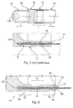
- the invention provides at least one inner glue joint 46 and / or an outer glue joint 48 whose thickness is variable from one free edge 50, on the end side, to the other free edge 52, on the tube side, said seals (46, 48).
- the bonded bond 40 comprises an inner glue joint 46 and an outer glue joint 48, the tip 44 and the tube 42 comprising two bonded surfaces ( S1 , S2 ) therebetween. Still preferably, the bonded surfaces ( S1 , S2 ) of the connection 40 extend over the entire length of L superposition between the endpiece 44 and the tube 42 and about a longitudinal axis L40 .
- the seals (46, 48) have increased thicknesses at the free edges (50, 52) of the seals, and preferably a greater increased thickness at the tip end 50, at the bottom of the groove, than the increased thickness at the side. tube 52.
- the throat 54 is machined in the end piece 44 so as to generate a housing of variable thickness and the glue to be blown is injected.
- the tip 44 and the tube 42 having cylindrical sections, the bonded surfaces ( S1 , S2 ) and the seals (46, 48) are also cylindrical.
- end piece 44 and the tube 42 could also have other closed or semi-closed sections around the longitudinal axis L40 of the link 40, such as elliptical sections, U, W, I or any polygon open or closed.
- the invention means any section conferring a non-planar volume to the endpiece 44 and the tube 42 around the longitudinal axis L40 , that is to say a volume with at least a part hollow, open or closed, along the longitudinal axis L40 .
- the seals (46, 48) also have a closed or semi-closed section around the longitudinal axis L40 .
- the seals (46, 48) have closed or semi-closed sections of substantially identical profiles to the closed or semi-closed sections of the endpiece 44 and the tube 42 about the longitudinal axis L40 of the link 40.
- the variation in thickness of the glue joints (46, 48) provided by the invention makes it possible to reduce the gradient of the shear overtrains.
- the glue joints (46, 48), of reduced length moreover, work in a more homogeneous manner, and their median part now ensures a more significant recovery efforts.
- Glued connection 40 now works in an optimized manner since it does not exceed the maximum breaking strength of the glue.
- the shear over-stress is greater at the free edge 50, the end piece at the bottom of the groove, than the right free edge 52, tube side, the variation in thickness is such that the glue joints Inside and outside (46, 48) are thicker to the right of the free edge 50, tip end, than to the right of the free edge 52, tube side.
- the bonded bond 40 comprises an inner glue joint 46 and an outer glue joint 48, and the two glue joints (46, 48) follow a gradual and non-linear variation in thickness between their free edge 50, tip end, and their other free edge 52, tube side.
- an adhesive joint (46, 48) of the glued connection 40 could follow a gradual and non-linear variation in thickness between its free edge 50, tip end, and its other free edge 52, tube side.
- the invention means a variation in a curve without bearing of the free edge 50 at the free edge 52.
- this non-linear variation in thickness is preferred because it corresponds better to the ideal variation profile obtained after a numerical modeling of the glued connection 40 and different finite element calculations simulating the behavior of the parts (42, 44) and bond bonded 40 under effort.
- the two glue joints (46, 48) of the glued connection 40 may follow linear variations in thickness between the free edge 50 at the tip end and the other free edge 52 at the tube side.
- a glue joint (46, 48) decreases linearly.
- these linear variations in the thickness of the glue joints (46, 48) facilitate the machining of the groove 54 in the endpiece 44.
- the invention provides at least one outer reduction of thickness R1 , R2 of the nozzle 44 to the right of the free edge 52, tube side, of at least one seal (46, 48).
- the invention means a reduction made on the faces F1 , F2 of the tip 44 outside the bonded bond 40 and therefore not glued.
- the bonded bond 40 comprising an inner adhesive seal 46 and an outer adhesive seal 48
- the nozzle 44 comprises an outer end E44 of reduced thickness in line with the free edge 52, on the tube side, of the outer seal 48, and an inner end I44 of reduced thickness to the right of the free edge 52, tube side, of the inner seal 46.
- the outer ends E44 and inner I44 offer an external reduction of thickness R1 , R2 progressive, that is to say without bearing.
- the end piece 44 comprising an inner skirt 80 and an outer ring 82 between which is provided the groove 54, the inner skirt 80 and the outer ring 82 of the end piece 44 each have an outer reduction of thickness R1 , R2 to the right of the free edge 52 of the seals (46, 48).
- the method of producing a bonding bond 40 according to the invention between a first piece (42, 62) and a second piece (44, 64), with a length L of superposition, and subjected to forces T in at least one axial direction consists in producing at least one glue joint (46, 48) on at least part of the length L between said two pieces, this at least one seal (46, 48) having a thickness variable in the direction of the forces to which the first and second parts are subjected.
- the method according to the invention also provides for producing at least one adhesive seal (46, 48) having, in the longitudinal direction of the forces, a thickness greater than the right of each of the two free edges (50, 52) of said seal relative at the middle zone, this in the axial direction of the efforts T.
- the thickness variation provided by the invention brings a progressivity in the rigidity of the adhesive joint (46, 48) so that the end zones, where the relative deformations of the two parts to be assembled (42, 44) are maximum, constitute more flexible portions of the glue joint, and so that the central zone, made thinner, constitutes a more rigid portion of the joint.
- the method according to the invention consists in producing a thickness variation such that the adhesive joint (46, 48) at the edge of a free edge (50) is thicker than the adhesive joint ( 46, 48) to the right of the other free edge (52) of said seal.
- the glued connection 40 comprising at least one inner glue joint 46 and / or an outer glue joint 48 whose thickness is variable from one to another.
- a free edge 50, on the tip side, at the other free edge 52, tube side, of said seals (46, 48) the method according to the invention consists in machining a groove 54 in the end piece 44 according to the variation profile sought thickness of the seal (s) adhesive (46, 48), to introduce the tube 42 in the nozzle 44, and to inject glue into the groove 54 by avoiding the introduction of air bubbles.
- the method is perfectly applicable in exactly the same way to a connection bonded between two open-profile parts or between parts without a form of revolution.
- the method according to the invention is preferably adapted to the realization of a bonded bond 40 between a metal end piece 44 and a tube 42 of composite materials for the manufacture of a connecting rod, two end pieces 44 being attached to both ends of a tube 42 via glued connections 40 to form a connecting rod.
- the invention covers a connecting rod comprising at least one end piece 44, preferably metal, attached to a tube 42, preferably made of composite materials, with at least one bonded connection 40 according to the invention.
- such a rod is intended for aeronautical use and the production of aircraft structures.
- the method according to the invention could also be adapted to the realization of any connecting rod structure or a connection between a wind turbine blade and the rotor of the wind turbine, the blade may comprise a cylindrical base to be fixed on a cylindrical end integral with the rotor of the wind turbine.
- the method according to the invention could also be applicable to a bond bonded between two pieces made of composite materials or between two metal parts.
- the invention relates to the realization of an assembly by a glued connection 40 between rigid parts (40, 42), that is to say whose modulus of elasticity is greater than 50 GPa. .
Landscapes
- Engineering & Computer Science (AREA)
- General Engineering & Computer Science (AREA)
- Mechanical Engineering (AREA)
- Standing Axle, Rod, Or Tube Structures Coupled By Welding, Adhesion, Or Deposition (AREA)
- Lining Or Joining Of Plastics Or The Like (AREA)
Applications Claiming Priority (1)
| Application Number | Priority Date | Filing Date | Title |
|---|---|---|---|
| FR1259920A FR2997034B1 (fr) | 2012-10-18 | 2012-10-18 | Procede de collage de deux pieces soumises a des efforts de traction, pieces collees obtenues |
Publications (2)
| Publication Number | Publication Date |
|---|---|
| EP2722533A1 true EP2722533A1 (de) | 2014-04-23 |
| EP2722533B1 EP2722533B1 (de) | 2018-05-02 |
Family
ID=47356211
Family Applications (1)
| Application Number | Title | Priority Date | Filing Date |
|---|---|---|---|
| EP13306423.8A Active EP2722533B1 (de) | 2012-10-18 | 2013-10-17 | Verklebeverfahren von zwei unter Zugkraft stehenden Teilen und so erhaltene verklebte Teile |
Country Status (3)
| Country | Link |
|---|---|
| US (1) | US9227375B2 (de) |
| EP (1) | EP2722533B1 (de) |
| FR (1) | FR2997034B1 (de) |
Cited By (10)
| Publication number | Priority date | Publication date | Assignee | Title |
|---|---|---|---|---|
| WO2015164704A1 (en) * | 2014-04-24 | 2015-10-29 | Zodiac Seats Us Llc | Double shear bonded joint and method for making same |
| EP3395591A1 (de) * | 2017-04-06 | 2018-10-31 | THK Rhythm Automotive GmbH | Fahrwerkbauteil und verfahren zu dessen herstellung |
| WO2019223957A1 (de) * | 2018-05-25 | 2019-11-28 | Zf Friedrichshafen Ag | Fahrwerklenker für ein kraftfahrzeug |
| WO2019224019A1 (de) * | 2018-05-25 | 2019-11-28 | Zf Friedrichshafen Ag | Verfahren zur herstellung einer achsstrebe sowie achsstrebe für ein fahrzeug |
| WO2020030369A1 (de) * | 2018-08-08 | 2020-02-13 | Zf Friedrichshafen Ag | Mehrpunktlenker für ein fahrwerk eines kraftfahrzeugs |
| WO2020030370A1 (de) * | 2018-08-08 | 2020-02-13 | Zf Friedrichshafen Ag | Mehrpunktlenker für ein fahrwerk eines kraftfahrzeugs |
| WO2020126247A1 (de) * | 2018-12-17 | 2020-06-25 | Zf Friedrichshafen Ag | Fahrwerklenker für ein kraftfahrzeug |
| WO2020229009A1 (de) * | 2019-05-10 | 2020-11-19 | Zf Friedrichshafen Ag | Gebauter dreipunktlenker |
| RU2754473C2 (ru) * | 2017-04-28 | 2021-09-02 | Цф Фридрихсхафен Аг | Реактивная штанга и способ изготовления реактивной штанги |
| RU2779769C2 (ru) * | 2018-05-25 | 2022-09-13 | Цф Фридрихсхафен Аг | Рычаг ходовой части для моторного безрельсового транспортного средства |
Families Citing this family (7)
| Publication number | Priority date | Publication date | Assignee | Title |
|---|---|---|---|---|
| US10138925B2 (en) * | 2014-05-26 | 2018-11-27 | Fujikura Rubber Ltd. | FRP drive shaft |
| US11041585B2 (en) * | 2016-06-08 | 2021-06-22 | Avtechtyee Inc. | Fitting collar and tube-fitting assemblies incorporating fitting collars |
| DE102017003024A1 (de) | 2017-03-29 | 2018-10-04 | Ralph Funck | Abschlusselement zur Krafteinleitung in ein vorgefertigtes Faserkunststoffverbundrohr |
| DE102017213563A1 (de) * | 2017-08-04 | 2019-02-07 | Zf Friedrichshafen Ag | Dreipunktlenker und Herstellungsverfahren für einen Dreipunktlenker |
| US10605285B2 (en) * | 2017-08-08 | 2020-03-31 | Divergent Technologies, Inc. | Systems and methods for joining node and tube structures |
| DE102018208268A1 (de) * | 2018-05-25 | 2019-11-28 | Zf Friedrichshafen Ag | Verfahren zum Herstellen einer Klebeverbindung sowie eine Achstrebe für ein Fahrzeug |
| KR20250164877A (ko) * | 2020-11-06 | 2025-11-25 | 디엠씨 글로벌 아이엔씨. | 첨가적 마찰 교반에 의해 제조되는 천이 접합부를 위한 방법 및 장치 |
Citations (3)
| Publication number | Priority date | Publication date | Assignee | Title |
|---|---|---|---|---|
| US3545795A (en) * | 1969-01-07 | 1970-12-08 | Heinrich Hertel | Joint |
| EP0046869A1 (de) * | 1980-08-28 | 1982-03-10 | Robert Bosch Gmbh | Anschluss zur Übertragung von Drehmomenten in torsionsweiche Rohre |
| EP2508764A1 (de) * | 2011-04-04 | 2012-10-10 | Bell Helicopter Textron Inc. | Selbstpumpendes und selbstansaugendes Klebstoffverbindungssystem |
Family Cites Families (10)
| Publication number | Priority date | Publication date | Assignee | Title |
|---|---|---|---|---|
| DE2855570C2 (de) * | 1978-12-22 | 1985-06-20 | Messerschmitt-Bölkow-Blohm GmbH, 8012 Ottobrunn | Stabförmiges Bauelement |
| US4238539A (en) * | 1979-05-29 | 1980-12-09 | Celanese Corporation | Fiber reinforced composite shaft with metallic connector sleeves mounted by a knurl interlock |
| US4792320A (en) * | 1985-09-18 | 1988-12-20 | A. O. Smith Corporation | Composite tubular structure |
| US5318374A (en) * | 1992-09-23 | 1994-06-07 | The Boeing Company | Composite tube structure |
| US7427237B2 (en) * | 2002-01-03 | 2008-09-23 | Burkett Jerald S | Load sharing composite shaft |
| US6910617B2 (en) * | 2002-03-06 | 2005-06-28 | Torque-Traction Technologies, Inc. | Method for securing a yoke to a tube using magnetic pulse welding techniques |
| JP2004028323A (ja) * | 2002-05-01 | 2004-01-29 | Hidesaburo Ishii | 管継手の継手主体部装置、および継手主体部装置に用いる結合環部材 |
| US8205315B2 (en) * | 2006-11-01 | 2012-06-26 | Tyee Aircraft | Composite tube assemblies and methods of forming the same |
| US8414724B2 (en) * | 2006-12-02 | 2013-04-09 | The Boeing Company | Composite tube having cobonded end fittings and method of making same |
| JP5683798B2 (ja) * | 2009-08-31 | 2015-03-11 | 藤倉ゴム工業株式会社 | Frp製駆動シャフト |
-
2012
- 2012-10-18 FR FR1259920A patent/FR2997034B1/fr active Active
-
2013
- 2013-10-17 EP EP13306423.8A patent/EP2722533B1/de active Active
- 2013-10-18 US US14/057,021 patent/US9227375B2/en not_active Expired - Fee Related
Patent Citations (3)
| Publication number | Priority date | Publication date | Assignee | Title |
|---|---|---|---|---|
| US3545795A (en) * | 1969-01-07 | 1970-12-08 | Heinrich Hertel | Joint |
| EP0046869A1 (de) * | 1980-08-28 | 1982-03-10 | Robert Bosch Gmbh | Anschluss zur Übertragung von Drehmomenten in torsionsweiche Rohre |
| EP2508764A1 (de) * | 2011-04-04 | 2012-10-10 | Bell Helicopter Textron Inc. | Selbstpumpendes und selbstansaugendes Klebstoffverbindungssystem |
Cited By (20)
| Publication number | Priority date | Publication date | Assignee | Title |
|---|---|---|---|---|
| WO2015164704A1 (en) * | 2014-04-24 | 2015-10-29 | Zodiac Seats Us Llc | Double shear bonded joint and method for making same |
| US10781840B2 (en) | 2014-04-24 | 2020-09-22 | Safran Seats Usa Llc | Double shear bonded joint and method for making same |
| EP3395591A1 (de) * | 2017-04-06 | 2018-10-31 | THK Rhythm Automotive GmbH | Fahrwerkbauteil und verfahren zu dessen herstellung |
| US11279190B2 (en) | 2017-04-28 | 2022-03-22 | Zf Friedrichshafen Ag | Axle strut and method for producing an axle strut |
| EP3615357B1 (de) * | 2017-04-28 | 2021-11-03 | ZF Friedrichshafen AG | Achsstrebe |
| RU2754473C2 (ru) * | 2017-04-28 | 2021-09-02 | Цф Фридрихсхафен Аг | Реактивная штанга и способ изготовления реактивной штанги |
| JP2021525193A (ja) * | 2018-05-25 | 2021-09-24 | ツェットエフ、フリードリッヒスハーフェン、アクチエンゲゼルシャフトZf Friedrichshafen Ag | 原動機付き車両用のシャシコントロールアーム |
| WO2019223957A1 (de) * | 2018-05-25 | 2019-11-28 | Zf Friedrichshafen Ag | Fahrwerklenker für ein kraftfahrzeug |
| WO2019224019A1 (de) * | 2018-05-25 | 2019-11-28 | Zf Friedrichshafen Ag | Verfahren zur herstellung einer achsstrebe sowie achsstrebe für ein fahrzeug |
| RU2779769C2 (ru) * | 2018-05-25 | 2022-09-13 | Цф Фридрихсхафен Аг | Рычаг ходовой части для моторного безрельсового транспортного средства |
| US11173763B2 (en) | 2018-05-25 | 2021-11-16 | Zf Friedrichshafen Ag | Chassis link for a motor vehicle |
| WO2020030370A1 (de) * | 2018-08-08 | 2020-02-13 | Zf Friedrichshafen Ag | Mehrpunktlenker für ein fahrwerk eines kraftfahrzeugs |
| CN112533780A (zh) * | 2018-08-08 | 2021-03-19 | 采埃孚股份公司 | 用于机动车辆的底盘的多点连杆 |
| US11298997B2 (en) | 2018-08-08 | 2022-04-12 | Zf Friedrichshafen Ag | Multi-point link for an undercarriage of a motor vehicle |
| WO2020030369A1 (de) * | 2018-08-08 | 2020-02-13 | Zf Friedrichshafen Ag | Mehrpunktlenker für ein fahrwerk eines kraftfahrzeugs |
| US11485185B2 (en) | 2018-08-08 | 2022-11-01 | Zf Friedrichshafen Ag | Multi-point link for a chassis of a motor vehicle |
| WO2020126247A1 (de) * | 2018-12-17 | 2020-06-25 | Zf Friedrichshafen Ag | Fahrwerklenker für ein kraftfahrzeug |
| US11642927B2 (en) | 2018-12-17 | 2023-05-09 | Zf Friedrichshafen Ag | Chassis link for a motor vehicle |
| RU2807469C2 (ru) * | 2018-12-17 | 2023-11-15 | Цф Фридрихсхафен Аг | Рычаг подвески ходовой части для моторного безрельсового транспортного средства |
| WO2020229009A1 (de) * | 2019-05-10 | 2020-11-19 | Zf Friedrichshafen Ag | Gebauter dreipunktlenker |
Also Published As
| Publication number | Publication date |
|---|---|
| EP2722533B1 (de) | 2018-05-02 |
| FR2997034B1 (fr) | 2015-05-01 |
| US9227375B2 (en) | 2016-01-05 |
| US20140112708A1 (en) | 2014-04-24 |
| FR2997034A1 (fr) | 2014-04-25 |
Similar Documents
| Publication | Publication Date | Title |
|---|---|---|
| EP2722533B1 (de) | Verklebeverfahren von zwei unter Zugkraft stehenden Teilen und so erhaltene verklebte Teile | |
| BE1021537B1 (fr) | Bielle monobloc | |
| EP3827159B1 (de) | Turbomaschinenschaufel mit einem schutzmantel mit verbesserter haftfestigkeit | |
| EP2550153A1 (de) | Verfahren zur kontinuierlichen herstellung eines verbindungsteils aus einem verbundstoff | |
| EP2454473B1 (de) | Vorrichtung zur montage der abschnitte von windturbinenschaufeln und verfahren zur verbindung der abschnitte von windturbinenschaufeln | |
| EP1824696A1 (de) | Aus mindestens zwei benachbarten glaselementen bestehendes komplexes trennwandglas und verfahren zur herstellung des komplexen trennwandglases | |
| EP3180528B1 (de) | Gelenkverbindungsanordnung | |
| EP2692631B1 (de) | Spant eines Luftfahrzeugs mit verjüngtem Abschnitt | |
| FR2869655A1 (fr) | Procede d'assemblage de pieces structurales et assemblage obtenu. | |
| EP3194104B1 (de) | Verfahren zur anordnung von zwei blechkomponenten wie etwa fahrzeugkarosseriekomponenten | |
| CA2481929C (fr) | Dispositif d'equipement d'un trou dans un panneau et panneau ainsi equipe | |
| EP3060391B1 (de) | Verbundene anordnung mit einer zwischendeformationsschicht mit variabler flexibilität | |
| EP2622232B1 (de) | Geriffelter haltewinkel aus einem verbundstoff | |
| WO2021083914A1 (fr) | Porte-diaphragme pour amortisseur de type oleopneumatique | |
| FR2867151A1 (fr) | Longeron de fuselage pour aeronef et caisson central equipe d'un tel longeron | |
| CA3051883C (fr) | Procede pour le decollement d'un element metallique colle a un element en materiau composite | |
| EP1798429B1 (de) | Rohrförmige Pleuelstange aus einem Verbundmaterial und ein entsprechendes Herstellungsverfahren | |
| FR3011875A1 (fr) | Aube de turbomachine a profil asymetrique | |
| EP2722538A1 (de) | Spannungsentlasteter Gabelkopf und Verfahren zur Spannungsentlastung eines solchen | |
| FR2970897A1 (fr) | Structure fibreuse formant une bride et une contre-bride | |
| EP2679855B1 (de) | Elastisches Lager für Kraftfahrzeug | |
| BE1016607A3 (fr) | Element structurel de construction en verre. | |
| FR3041556A1 (fr) | Assemblage d’elements en tole metallique comprenant une feuillure | |
| EP4532967B1 (de) | Rohrförmiges bauteil mit einem gewindeanschlusselement | |
| WO2024208803A1 (fr) | Assemblage comportant au moins une piece composite et des moyens de fixation |
Legal Events
| Date | Code | Title | Description |
|---|---|---|---|
| PUAI | Public reference made under article 153(3) epc to a published international application that has entered the european phase |
Free format text: ORIGINAL CODE: 0009012 |
|
| AK | Designated contracting states |
Kind code of ref document: A1 Designated state(s): AL AT BE BG CH CY CZ DE DK EE ES FI FR GB GR HR HU IE IS IT LI LT LU LV MC MK MT NL NO PL PT RO RS SE SI SK SM TR |
|
| AX | Request for extension of the european patent |
Extension state: BA ME |
|
| 17P | Request for examination filed |
Effective date: 20141023 |
|
| RBV | Designated contracting states (corrected) |
Designated state(s): AL AT BE BG CH CY CZ DE DK EE ES FI FR GB GR HR HU IE IS IT LI LT LU LV MC MK MT NL NO PL PT RO RS SE SI SK SM TR |
|
| 17Q | First examination report despatched |
Effective date: 20151109 |
|
| STAA | Information on the status of an ep patent application or granted ep patent |
Free format text: STATUS: EXAMINATION IS IN PROGRESS |
|
| GRAP | Despatch of communication of intention to grant a patent |
Free format text: ORIGINAL CODE: EPIDOSNIGR1 |
|
| STAA | Information on the status of an ep patent application or granted ep patent |
Free format text: STATUS: GRANT OF PATENT IS INTENDED |
|
| INTG | Intention to grant announced |
Effective date: 20171215 |
|
| GRAS | Grant fee paid |
Free format text: ORIGINAL CODE: EPIDOSNIGR3 |
|
| GRAA | (expected) grant |
Free format text: ORIGINAL CODE: 0009210 |
|
| STAA | Information on the status of an ep patent application or granted ep patent |
Free format text: STATUS: THE PATENT HAS BEEN GRANTED |
|
| AK | Designated contracting states |
Kind code of ref document: B1 Designated state(s): AL AT BE BG CH CY CZ DE DK EE ES FI FR GB GR HR HU IE IS IT LI LT LU LV MC MK MT NL NO PL PT RO RS SE SI SK SM TR |
|
| REG | Reference to a national code |
Ref country code: GB Ref legal event code: FG4D Free format text: NOT ENGLISH |
|
| REG | Reference to a national code |
Ref country code: CH Ref legal event code: EP Ref country code: AT Ref legal event code: REF Ref document number: 995575 Country of ref document: AT Kind code of ref document: T Effective date: 20180515 |
|
| REG | Reference to a national code |
Ref country code: DE Ref legal event code: R096 Ref document number: 602013036826 Country of ref document: DE Ref country code: IE Ref legal event code: FG4D Free format text: LANGUAGE OF EP DOCUMENT: FRENCH |
|
| REG | Reference to a national code |
Ref country code: DE Ref legal event code: R096 Ref document number: 602013036826 Country of ref document: DE |
|
| REG | Reference to a national code |
Ref country code: NL Ref legal event code: MP Effective date: 20180502 |
|
| REG | Reference to a national code |
Ref country code: LT Ref legal event code: MG4D |
|
| PG25 | Lapsed in a contracting state [announced via postgrant information from national office to epo] |
Ref country code: SE Free format text: LAPSE BECAUSE OF FAILURE TO SUBMIT A TRANSLATION OF THE DESCRIPTION OR TO PAY THE FEE WITHIN THE PRESCRIBED TIME-LIMIT Effective date: 20180502 Ref country code: ES Free format text: LAPSE BECAUSE OF FAILURE TO SUBMIT A TRANSLATION OF THE DESCRIPTION OR TO PAY THE FEE WITHIN THE PRESCRIBED TIME-LIMIT Effective date: 20180502 Ref country code: LT Free format text: LAPSE BECAUSE OF FAILURE TO SUBMIT A TRANSLATION OF THE DESCRIPTION OR TO PAY THE FEE WITHIN THE PRESCRIBED TIME-LIMIT Effective date: 20180502 Ref country code: FI Free format text: LAPSE BECAUSE OF FAILURE TO SUBMIT A TRANSLATION OF THE DESCRIPTION OR TO PAY THE FEE WITHIN THE PRESCRIBED TIME-LIMIT Effective date: 20180502 Ref country code: NO Free format text: LAPSE BECAUSE OF FAILURE TO SUBMIT A TRANSLATION OF THE DESCRIPTION OR TO PAY THE FEE WITHIN THE PRESCRIBED TIME-LIMIT Effective date: 20180802 Ref country code: BG Free format text: LAPSE BECAUSE OF FAILURE TO SUBMIT A TRANSLATION OF THE DESCRIPTION OR TO PAY THE FEE WITHIN THE PRESCRIBED TIME-LIMIT Effective date: 20180802 |
|
| REG | Reference to a national code |
Ref country code: FR Ref legal event code: PLFP Year of fee payment: 6 |
|
| PG25 | Lapsed in a contracting state [announced via postgrant information from national office to epo] |
Ref country code: GR Free format text: LAPSE BECAUSE OF FAILURE TO SUBMIT A TRANSLATION OF THE DESCRIPTION OR TO PAY THE FEE WITHIN THE PRESCRIBED TIME-LIMIT Effective date: 20180803 Ref country code: RS Free format text: LAPSE BECAUSE OF FAILURE TO SUBMIT A TRANSLATION OF THE DESCRIPTION OR TO PAY THE FEE WITHIN THE PRESCRIBED TIME-LIMIT Effective date: 20180502 Ref country code: LV Free format text: LAPSE BECAUSE OF FAILURE TO SUBMIT A TRANSLATION OF THE DESCRIPTION OR TO PAY THE FEE WITHIN THE PRESCRIBED TIME-LIMIT Effective date: 20180502 Ref country code: NL Free format text: LAPSE BECAUSE OF FAILURE TO SUBMIT A TRANSLATION OF THE DESCRIPTION OR TO PAY THE FEE WITHIN THE PRESCRIBED TIME-LIMIT Effective date: 20180502 Ref country code: HR Free format text: LAPSE BECAUSE OF FAILURE TO SUBMIT A TRANSLATION OF THE DESCRIPTION OR TO PAY THE FEE WITHIN THE PRESCRIBED TIME-LIMIT Effective date: 20180502 |
|
| REG | Reference to a national code |
Ref country code: AT Ref legal event code: MK05 Ref document number: 995575 Country of ref document: AT Kind code of ref document: T Effective date: 20180502 |
|
| PG25 | Lapsed in a contracting state [announced via postgrant information from national office to epo] |
Ref country code: CZ Free format text: LAPSE BECAUSE OF FAILURE TO SUBMIT A TRANSLATION OF THE DESCRIPTION OR TO PAY THE FEE WITHIN THE PRESCRIBED TIME-LIMIT Effective date: 20180502 Ref country code: SK Free format text: LAPSE BECAUSE OF FAILURE TO SUBMIT A TRANSLATION OF THE DESCRIPTION OR TO PAY THE FEE WITHIN THE PRESCRIBED TIME-LIMIT Effective date: 20180502 Ref country code: PL Free format text: LAPSE BECAUSE OF FAILURE TO SUBMIT A TRANSLATION OF THE DESCRIPTION OR TO PAY THE FEE WITHIN THE PRESCRIBED TIME-LIMIT Effective date: 20180502 Ref country code: EE Free format text: LAPSE BECAUSE OF FAILURE TO SUBMIT A TRANSLATION OF THE DESCRIPTION OR TO PAY THE FEE WITHIN THE PRESCRIBED TIME-LIMIT Effective date: 20180502 Ref country code: DK Free format text: LAPSE BECAUSE OF FAILURE TO SUBMIT A TRANSLATION OF THE DESCRIPTION OR TO PAY THE FEE WITHIN THE PRESCRIBED TIME-LIMIT Effective date: 20180502 Ref country code: AT Free format text: LAPSE BECAUSE OF FAILURE TO SUBMIT A TRANSLATION OF THE DESCRIPTION OR TO PAY THE FEE WITHIN THE PRESCRIBED TIME-LIMIT Effective date: 20180502 Ref country code: RO Free format text: LAPSE BECAUSE OF FAILURE TO SUBMIT A TRANSLATION OF THE DESCRIPTION OR TO PAY THE FEE WITHIN THE PRESCRIBED TIME-LIMIT Effective date: 20180502 |
|
| REG | Reference to a national code |
Ref country code: DE Ref legal event code: R097 Ref document number: 602013036826 Country of ref document: DE |
|
| PG25 | Lapsed in a contracting state [announced via postgrant information from national office to epo] |
Ref country code: SM Free format text: LAPSE BECAUSE OF FAILURE TO SUBMIT A TRANSLATION OF THE DESCRIPTION OR TO PAY THE FEE WITHIN THE PRESCRIBED TIME-LIMIT Effective date: 20180502 Ref country code: IT Free format text: LAPSE BECAUSE OF FAILURE TO SUBMIT A TRANSLATION OF THE DESCRIPTION OR TO PAY THE FEE WITHIN THE PRESCRIBED TIME-LIMIT Effective date: 20180502 |
|
| PLBE | No opposition filed within time limit |
Free format text: ORIGINAL CODE: 0009261 |
|
| STAA | Information on the status of an ep patent application or granted ep patent |
Free format text: STATUS: NO OPPOSITION FILED WITHIN TIME LIMIT |
|
| 26N | No opposition filed |
Effective date: 20190205 |
|
| PG25 | Lapsed in a contracting state [announced via postgrant information from national office to epo] |
Ref country code: SI Free format text: LAPSE BECAUSE OF FAILURE TO SUBMIT A TRANSLATION OF THE DESCRIPTION OR TO PAY THE FEE WITHIN THE PRESCRIBED TIME-LIMIT Effective date: 20180502 |
|
| REG | Reference to a national code |
Ref country code: CH Ref legal event code: PL |
|
| GBPC | Gb: european patent ceased through non-payment of renewal fee |
Effective date: 20181017 |
|
| REG | Reference to a national code |
Ref country code: BE Ref legal event code: MM Effective date: 20181031 |
|
| PG25 | Lapsed in a contracting state [announced via postgrant information from national office to epo] |
Ref country code: MC Free format text: LAPSE BECAUSE OF FAILURE TO SUBMIT A TRANSLATION OF THE DESCRIPTION OR TO PAY THE FEE WITHIN THE PRESCRIBED TIME-LIMIT Effective date: 20180502 Ref country code: LU Free format text: LAPSE BECAUSE OF NON-PAYMENT OF DUE FEES Effective date: 20181017 |
|
| REG | Reference to a national code |
Ref country code: IE Ref legal event code: MM4A |
|
| PG25 | Lapsed in a contracting state [announced via postgrant information from national office to epo] |
Ref country code: BE Free format text: LAPSE BECAUSE OF NON-PAYMENT OF DUE FEES Effective date: 20181031 Ref country code: LI Free format text: LAPSE BECAUSE OF NON-PAYMENT OF DUE FEES Effective date: 20181031 Ref country code: CH Free format text: LAPSE BECAUSE OF NON-PAYMENT OF DUE FEES Effective date: 20181031 |
|
| PG25 | Lapsed in a contracting state [announced via postgrant information from national office to epo] |
Ref country code: GB Free format text: LAPSE BECAUSE OF NON-PAYMENT OF DUE FEES Effective date: 20181017 Ref country code: IE Free format text: LAPSE BECAUSE OF NON-PAYMENT OF DUE FEES Effective date: 20181017 |
|
| PG25 | Lapsed in a contracting state [announced via postgrant information from national office to epo] |
Ref country code: AL Free format text: LAPSE BECAUSE OF FAILURE TO SUBMIT A TRANSLATION OF THE DESCRIPTION OR TO PAY THE FEE WITHIN THE PRESCRIBED TIME-LIMIT Effective date: 20180502 |
|
| PG25 | Lapsed in a contracting state [announced via postgrant information from national office to epo] |
Ref country code: MT Free format text: LAPSE BECAUSE OF FAILURE TO SUBMIT A TRANSLATION OF THE DESCRIPTION OR TO PAY THE FEE WITHIN THE PRESCRIBED TIME-LIMIT Effective date: 20180502 |
|
| PG25 | Lapsed in a contracting state [announced via postgrant information from national office to epo] |
Ref country code: TR Free format text: LAPSE BECAUSE OF FAILURE TO SUBMIT A TRANSLATION OF THE DESCRIPTION OR TO PAY THE FEE WITHIN THE PRESCRIBED TIME-LIMIT Effective date: 20180502 |
|
| PG25 | Lapsed in a contracting state [announced via postgrant information from national office to epo] |
Ref country code: PT Free format text: LAPSE BECAUSE OF FAILURE TO SUBMIT A TRANSLATION OF THE DESCRIPTION OR TO PAY THE FEE WITHIN THE PRESCRIBED TIME-LIMIT Effective date: 20180502 |
|
| PG25 | Lapsed in a contracting state [announced via postgrant information from national office to epo] |
Ref country code: CY Free format text: LAPSE BECAUSE OF FAILURE TO SUBMIT A TRANSLATION OF THE DESCRIPTION OR TO PAY THE FEE WITHIN THE PRESCRIBED TIME-LIMIT Effective date: 20180502 Ref country code: HU Free format text: LAPSE BECAUSE OF FAILURE TO SUBMIT A TRANSLATION OF THE DESCRIPTION OR TO PAY THE FEE WITHIN THE PRESCRIBED TIME-LIMIT; INVALID AB INITIO Effective date: 20131017 Ref country code: MK Free format text: LAPSE BECAUSE OF NON-PAYMENT OF DUE FEES Effective date: 20180502 |
|
| PG25 | Lapsed in a contracting state [announced via postgrant information from national office to epo] |
Ref country code: IS Free format text: LAPSE BECAUSE OF FAILURE TO SUBMIT A TRANSLATION OF THE DESCRIPTION OR TO PAY THE FEE WITHIN THE PRESCRIBED TIME-LIMIT Effective date: 20180902 |
|
| PGFP | Annual fee paid to national office [announced via postgrant information from national office to epo] |
Ref country code: DE Payment date: 20221020 Year of fee payment: 10 |
|
| REG | Reference to a national code |
Ref country code: DE Ref legal event code: R119 Ref document number: 602013036826 Country of ref document: DE |
|
| PG25 | Lapsed in a contracting state [announced via postgrant information from national office to epo] |
Ref country code: DE Free format text: LAPSE BECAUSE OF NON-PAYMENT OF DUE FEES Effective date: 20240501 |
|
| PGFP | Annual fee paid to national office [announced via postgrant information from national office to epo] |
Ref country code: FR Payment date: 20251022 Year of fee payment: 13 |