EP2722690A2 - Source sismique et procede de reduction de intermodulation. - Google Patents
Source sismique et procede de reduction de intermodulation. Download PDFInfo
- Publication number
- EP2722690A2 EP2722690A2 EP13188922.2A EP13188922A EP2722690A2 EP 2722690 A2 EP2722690 A2 EP 2722690A2 EP 13188922 A EP13188922 A EP 13188922A EP 2722690 A2 EP2722690 A2 EP 2722690A2
- Authority
- EP
- European Patent Office
- Prior art keywords
- sweep
- noise
- earth
- calculating
- earth response
- Prior art date
- Legal status (The legal status is an assumption and is not a legal conclusion. Google has not performed a legal analysis and makes no representation as to the accuracy of the status listed.)
- Withdrawn
Links
Images




Classifications
-
- G—PHYSICS
- G06—COMPUTING OR CALCULATING; COUNTING
- G06F—ELECTRIC DIGITAL DATA PROCESSING
- G06F17/00—Digital computing or data processing equipment or methods, specially adapted for specific functions
-
- G—PHYSICS
- G01—MEASURING; TESTING
- G01V—GEOPHYSICS; GRAVITATIONAL MEASUREMENTS; DETECTING MASSES OR OBJECTS; TAGS
- G01V1/00—Seismology; Seismic or acoustic prospecting or detecting
- G01V1/003—Seismic data acquisition in general, e.g. survey design
- G01V1/005—Seismic data acquisition in general, e.g. survey design with exploration systems emitting special signals, e.g. frequency swept signals, pulse sequences or slip sweep arrangements
-
- G—PHYSICS
- G01—MEASURING; TESTING
- G01V—GEOPHYSICS; GRAVITATIONAL MEASUREMENTS; DETECTING MASSES OR OBJECTS; TAGS
- G01V1/00—Seismology; Seismic or acoustic prospecting or detecting
- G01V1/28—Processing seismic data, e.g. for interpretation or for event detection
- G01V1/36—Effecting static or dynamic corrections on records, e.g. correcting spread; Correlating seismic signals; Eliminating effects of unwanted energy
- G01V1/37—Effecting static or dynamic corrections on records, e.g. correcting spread; Correlating seismic signals; Eliminating effects of unwanted energy specially adapted for seismic systems using continuous agitation of the ground, e.g. using pulse compression of frequency swept signals for enhancement of received signals
-
- G—PHYSICS
- G01—MEASURING; TESTING
- G01V—GEOPHYSICS; GRAVITATIONAL MEASUREMENTS; DETECTING MASSES OR OBJECTS; TAGS
- G01V2210/00—Details of seismic processing or analysis
- G01V2210/10—Aspects of acoustic signal generation or detection
- G01V2210/12—Signal generation
- G01V2210/121—Active source
- G01V2210/1214—Continuous
-
- G—PHYSICS
- G01—MEASURING; TESTING
- G01V—GEOPHYSICS; GRAVITATIONAL MEASUREMENTS; DETECTING MASSES OR OBJECTS; TAGS
- G01V2210/00—Details of seismic processing or analysis
- G01V2210/30—Noise handling
- G01V2210/32—Noise reduction
- G01V2210/324—Filtering
Definitions
- Embodiments of the subject matter disclosed herein generally relate to methods and systems for generating seismic waves and the mitigation of seismic noise artifacts due to intermodulation distortion (IMD) that may be present in the recorded data.
- IMD intermodulation distortion
- Land seismic data acquisition and processing may be used to generate a profile (image) of the geophysical structure under the ground (subsurface). While this profile does not provide an accurate location for oil and gas reservoirs, it suggests, to those trained in the field, the presence or absence of such reservoirs. Thus, providing a high-resolution image of the subsurface is important, for example, to those who need to determine whether the oil and gas reservoirs are located.
- Geophysical prospectors generate seismic waves in order to probe the subsurface (e.g., for imaging the earth). These acoustic waves may be generated from an explosive, implosive, impulsive, or a vibratory source executing swept-frequency (chirp) or random sequence. A recording of the acoustic reflection and refraction wavefronts that travel from the source to a receiver are used to produce a seismic field record. Variations in the travel times of the reflection events in these field records indicate the position of reflection and/or refraction surfaces within the earth.
- IMD distortion results from the modulation of signals containing two or more different frequencies in a non-linear system.
- the non-linear system of particular concern is the earth coupling and the two or more different frequencies may be (i) the frequency emitted by the source and (ii) harmonics of the same frequency.
- the intermodulation between each frequency component will form additional signals at frequencies that are not just at harmonic frequencies (integer multiples) of either, but also at the sum and difference frequencies of the original frequencies.
- There are other nonlinear mechanisms in the vibrator itself that produce IMD distortion products but since these effects are included in the measured ground force signal, they are incorporated into the source signature signal so that their distortion artifacts can be mitigated directly by performing a source signature deconvolution as a data processing step.
- a swept-frequency or chirp type seismic source may use a long pilot signal such as 2 to 64 seconds to ensure sufficient energy is imparted to the earth.
- a swept frequency type source the energy is emitted in the form of a sweep of regularly increasing (upsweep) or decreasing (downsweep) frequency in the seismic frequency range.
- the vibrations of the source are controlled by a control system, which can control the frequency and phase of the seismic signals.
- These sources are low energy and, thus, this causes noise problems that may affect the recorded seismic data.
- the source generated harmonic energy may be an additional source of energy manifesting as noise, distortion or interference with recorded data.
- the source emits only one frequency at a time and its harmonics, so nonlinear coupling effects in the earth will result in noise that is indistinguishable from harmonic noise.
- sub-harmonic energy can also be produced and any IMD products between sub-harmonics, fundamental or harmonics are also indistinguishable from sub-harmonic noise and its multiples.
- One exception is due to amplitude tapers that are generally applied at the start and end of a chirp.
- the taper intervals are usually between 100 to 1000 ms in duration.
- the reference contains more than one frequency due to the amplitude modulation of the chirp signal.
- IMD seismic waves are emitted in addition to fundamental, harmonic and sub-harmonic waves.
- vibratory sources may generate harmonics, sub-harmonics and IMD noise which can cross-feed with signals from other sources, giving misleading results when the signals are processed to separate the signals from each source.
- harmonics are a source of noise that can mask weak reflection signals from deeper layers.
- the method includes a step of receiving seismic data generated by actuating the one or more land seismic source with a first sweep and a second sweep; a step of calculating with a computing device a first earth response (h1est) corresponding to the first sweep; a step of calculating with the computing device a second earth response (h2est) corresponding to the second sweep; and a step of calculating the intermodulation noise (IMD) based on the first and second earth responses (h1 est, h2est).
- the second sweep is a time reverse sweep of the first sweep.
- a computing device for calculating intermodulation noise generated with one or more land seismic sources.
- the computing device includes an interface for receiving seismic data generated by actuating the one or more land seismic source with a first sweep and a second sweep; and a processor connected to the interface.
- the processor is configured to calculate a first earth response (h1est) corresponding to the first sweep, calculate a second earth response (h2est) corresponding to the second sweep, and calculate the intermodulation noise (IMD) based on the first and second earth responses (h1est, h2est).
- the second sweep is a time reverse sweep of the first sweep.
- non-transitory computer readable medium including computer executable instructions, wherein the instructions, when executed by a computer, implement the method noted above.
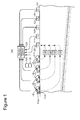
- Figure 1 illustrates a field seismic survey according to an exemplary embodiment
- Figure 2 is a graph illustrating a first measured force and a first pilot signal for a source driven by a first sweep according to an exemplary embodiment
- Figure 3 is a graph illustrating a second measured force and a second pilot signal for a source driven by a second sweep, which is the reverse of the first sweep, according to an exemplary embodiment
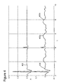
- Figure 4 is a graph illustrating earth responses with and without IMD noise when a source is driven by a first sweep according to an exemplary embodiment
- Figure 5 is a graph illustrating earth responses with and without IMD noise when the source is driven by a second sweep according to an exemplary embodiment
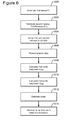
- Figure 6 is a flowchart illustrating a method for removing IMD noise from recorded seismic data according to an exemplary embodiment
- Figure 7 is a flowchart illustrating how to calculate the IMD noise according to an exemplary embodiment.
- Figure 8 is a schematic diagram of a computing device.
- a method for operating a vibratory source with two different pilot signals that are used alternately to drive the source is described.
- the second pilot signal may be a time-reversed version of the first pilot signal.
- the pilot signals may be a traditional sweep signal, e.g., a sine function, or a pseudo-random sweep, as discussed, for example, in U.S. Patent No. 7,859,945 (herein '945), the entire content of which is incorporated herein by reference.
- a land seismic system 100 that generates and also collects seismic data is discussed with reference to Figure 1 .
- the exemplary survey system 100 includes four vibrators 110, 111, 112, and 113 placed at the surface of the earth 101.
- Vibrators 110, 111, 112, and 113 may be conventional truck-mounted vertical P-wave vibrators; however, it is understood that other vibrators, such as horizontal shear-wave vibrators, may be utilized or even a mixture of both P-wave and shear wave vibrators.
- the deployment of the vibrators may vary widely depending upon the survey requirements. For example, for a 3-D survey the vibrators may be spaced far apart and not collinear with one another.
- Each vibrator may be equipped with a sweep generator module and control system electronics.
- Figure 1 shows vibrator 113 having the sweep generator module 113a and the control system electronics 113b.
- each vibrator After receiving a start command, for example, initiated via a telemetry link with the recording system or by the operator of the vibrator, each vibrator begins sweeping.
- the vibrators are not coordinated to sweep simultaneously, which is different from many existing methods.
- the vibrators are coordinated to sweep simultaneously.
- Each vibrator sweep generator may be loaded with a unique pilot signal.
- the vibrator sweep generator receives its corresponding pilot signal from a central controller 129.
- the pilot signal may be generated locally or centrally.
- the sensors can be motion sensors, such as accelerometers mounted to the reaction mass, the base plate of the vibrator, or the earth immediately adjacent to the vibrator, a transducer or combination of transducers configured to measure the differential pressure in the actuation chamber of the vibrator, a load cell attached to the bottom of the base plate for measurement of the ground force (contact force), or a weighted sum of the base plate and the reaction mass accelerometers useful for estimating the ground force.
- the sensor could comprise strain gauges mounted on the driven structure of the vibrator to provide an estimate of the ground force. Thus, these sensors provide the ground force signals to the vibrator separation system 126.
- the pilot or reference signal generated by the vibrator controller that the vibrator output follows or (ii) a Kalman filter estimate of the ground force provided by the vibrator controller can be utilized for the sensor movement or (iii) another signal that is representative of the signal imparted into the earth, for example the base plate accelerometer signal.
- the sensor measurement, or some filtered version of the sensor measurement is the measured signal and represents the actual source vibration imparted to the earth by the vibrator.
- the output of the vibrator may be different from the pilot signal.
- the measured signals may be transmitted to a recording system 128 by hardwired link, a radio telemetry link, or by a separate acquisition system that records and stores the measured signals so that the measured signals can be integrated with the acquired seismic data set at a later time.
- the recording system 128 may be implemented in the same hardware as the central controller 129.
- Receiver sensors are positioned at the surface of the earth 101 in the survey region at locations displaced from the vibrator position.
- the receiver sensors may be conventional moving coil type geophones, Micro Electro-Mechanical System (MEMS) sensor elements, or hydrophones for transition zone areas like marshes.
- MEMS Micro Electro-Mechanical System
- a receiver sensor may include a group of receiver sensors arranged as a receiver array to help attenuate ground roll or other noise modes.
- Receiver sensors are not limited to vertical component type sensors; horizontal geophones and 3-C geophones/accelerometers may also be used depending upon the nature of the survey to be conducted.
- receivers 120, 121, 122, 123, and 124 will be considered single component vertical geophones configured to function as point receivers in this embodiment.
- each vibrator 110, 111, 112, and 113 travels through the earth from each vibrator to the receiver sensors 120, 121, 122, 123, and 124 in the survey area.
- the vibratory signal received by each receiver sensor will actually be a composite signal comprised of contributions from each vibratory source.
- Transfer functions 130, 131, 132, and 133 represent the transmission path response from vibrator 110, 111, 112, and 113 to receiver sensor 120 respectively.
- the transfer function will depend upon the vibratory signal radiated by each vibrator, the refraction and reflection by the subterranean formations of the vibratory source energy, and the response of the receiver sensor. Subsequent processing steps can be used to remove the embedded response due to the choice of source measured signal and receiver response.
- IMD noise is mainly associated with random sweeps.
- the method discussed next can also be applied to non-random sweeps, for example, traditional sine sweeps, by replacing the IMD noise term with a harmonic distortion noise term "Dist.”
- the exemplary embodiments discussed next exemplify the IMD noise but the same embodiments can be applied to other distortion models.
- the IMD noise refers to an additive noise that corresponds to a difference between a measured force f 1 (t) and a real source s 1 (t) representing the actual propagated signal
- the force f 1 (t) is measured, for example, with a sensor located at the vibrator, the IMD noise imd 1 is calculated, and the real source s 1 (t) is the real seismic signal radiated into the earth in response to the applied force.
- h(t) is the real transfer function (response) of the earth (it cannot be measured exactly because noise is always present)
- g 1 (t) is the seismic data recorded with the seismic recorders shown in Figure 1 .
- Figure 1 shows plural sources, the method now discussed can be applied to a single seismic source. However, the method may also be applied to plural sources as shown in Figure 1 .
- the force f 1 (t) may be considered to be identical to the pilot signal applied to the source. For this reason, this document refers interchangeably to the (measured) force and the pilot signal as f 1 (t). The same is true for the time-reversed version of f 1 , which is f 2 .
- both equations (1) and (2) are written in the time domain.
- both equations can be transformed into the frequency domain.
- the equations can be transformed into another domain, e.g., tau-p domain.
- ⁇ 1 " and " ⁇ 2 " are time delays corresponding to arrival times of seismic waves from different travel paths propagating from the source to the geophone receiver. Note that the earth response is causal, i.e., source seismic waves are not received prior to their emission.
- Hest f H f + IMD f ⁇ H f / F f .
- the estimated earth response may be calculated by deconvolution, i.e., spectral division of the seismic traces with the measured force. The deconvolution may be performed in the frequency domain.
- Equation (1) and (2) can now be solved (deconvolution) based on equation (3f), to determine the estimated earth responses H1 est and H2est:
- H ⁇ 1 ⁇ est f : G ⁇ 1 f ⁇ F ⁇ 1 f ⁇ F ⁇ 1 f ⁇ F ⁇ 1 f ⁇ + ⁇
- H ⁇ 2 ⁇ est f : G ⁇ 2 f ⁇ F ⁇ 2 f ⁇ F ⁇ 2 f ⁇ F ⁇ 2 f ⁇ + ⁇
- the subindex "f" indicates that those quantities are in the frequency domain and a bar in top of force F1 or F2 means complex conjugate respectively for the forward "F1" or reverse "F2" force signals.
- a fast fourier transform may be used to compute the frequency domain representations of the source signals and subindex "f" also serves as a digital frequency index.
- equation (4) can be evaluated at each digital frequency to form an array of values corresponding to an FFT of H1est and then IFFT (inverse fast fourier transform) can be taken to compute the time domain earth response estimate h1est.
- IFFT inverse fast fourier transform
- the IMD1 f is equal to IMD2 f * e -j2 ⁇ fSL because F1 f is equal to F2 f * e -j2 ⁇ fSL .
- the vibrator is well controlled so that the forward and reverse force signals are exactly the time reverse of one another, and that the nonlinear mechanism responsible for IMD production is well-behaved and repeatable. In practice, these assumptions may not hold true, but the real conditions may be close enough for IMD mitigation to be achieved.
- Figure 2 illustrates the measured force f 1 and the real source signal s 1 , which is the IMD corrupted signal radiated by the source when activated with the first pilot signal.
- Figure 3 illustrates the measured force f 2 and the real source signal s 2 , which is the IMD corrupted signal radiated by the source when activated with the second pilot signal. It is noted that the quantities shown in Figures 2 and 3 are synthetic values.
- the earth response (h1est) for the measured force f 1 is illustrated by curve 400 and the same response from which the noise has been removed (based on the method discussed above) is illustrated by curve 402 in Figure 4 . It is noted that the IMD noise artifacts 400a and 400b are removed in curve 402.
- the earth response (h2est) of the measured force f 2 is illustrated by curve 502 and the same response from which the noise has been removed (based on the method discussed above) is illustrated by curve 502 in Figure 5 . It is noted that the IMD noise artifacts 500a and 500b are removed in curve 502.
- Both Figures 4 and 5 illustrate the earth responses in the time domain.
- the measured signals were converted to the frequency domain using a fast Fourier Transform (FFT) that is a discretized version of the Fourier transform better suited for calculations using digital computers.
- FFT fast Fourier Transform
- IFFT inverse fast Fourier transform
- Initial estimates of the IMD source noise artifacts in h1est and h2est may be formed, in one embodiment, as follows.
- a cosine taper window operator "W(t)" with values W t that are zero for times outside the listen time and unity during most of the listen time may be used.
- IMD1 an IMD2 are time-flipped versions of one another may be exploited as follows.
- the reverse noise terms RNOISE1 and RNOISE2 in the deconvolved records are formed in the frequency domain as shown in equations (16) and (17).
- Those frequency domain arrays RNOISE1 and RNOISE2 are then inverse FFT'd to form their time domain representations arrays rnoise1 and rnoise2.
- a first sweep F1 is generated.
- the sweep F1 may be a sine function, or a pseudo-random sweep, etc.
- a second sweep F2 is generated.
- the second sweep F2 may be of the same type as the first sweep F1.
- the first sweep may be a forward sequence while the second sweep may be a reverse sequence.
- the second sweep F2 is generated such that it is a time reverse of the first sweep F1.
- the first and second sweeps are applied to one or more vibrators. In one application, the first sweep F1 is applied first and then the second sweep F2 is applied second. The energy imparted to the earth by the vibrators is recorded in step 606.
- a first earth response h1est is calculated based on a measured first force applied by the vibratory source to the ground (due to the first sweep F1) and in step 610 a second earth response h2es t is calculated based on a measured second force applied by the vibratory source to the ground (due to the second sweep F2).
- the earth responses are calculated in the frequency domain.
- the time reversal looks like a complex conjugate operation on the spectral data. Using this fact, it is possible to design noise estimates in the frequency domain, and reverse them in the time domain in step 612. Then, after an inverse Fourier transform IFFT is applied, it is possible to subtract the noise estimate from the earth response estimates in the time domain in step 614 to provide revised earth response estimates with IMD artifacts removed/mitigated.
- Step 612 of estimating the noise is now discussed in more details with regard to Figure 7 .
- the earth responses H1est and H2est have been calculated in steps 608 and 610 in the frequency domain.
- the earth responses in the frequency domain are transformed back to the time domain to obtain h1est and h2est in step 700.
- a window function W is selected in step 702 and applied to the earth responses h1 est and h2est to obtain the windowed earth responses Wh1est and Wh2est.
- the earth response estimates, h1est and h2est in the time domain are then combined to form "have" which is then transformed into the frequency domain with a Fourier transform to form a combined earth response called HAVE is defined in step 706.
- the reverse noises are transformed in the time domain to obtain the IMD noise artifact for each sweep and this noise is then used in step 614 to remove it from the earth response data in the time domain.
- the method may include a step of removing from the seismic data the intermodulation noise to obtain noise free seismic data and a step of generating an image of a surveyed subsurface based on the noise free seismic data.
- One or more of the steps of the above methods may be implemented in a computing system specifically configured to calculate the IMD noise.
- An example of a representative computing system capable of carrying out operations in accordance with the exemplary embodiments is illustrated in Figure 8 .
- Hardware, firmware, software or a combination thereof may be used to perform the various steps and operations described herein.
- the computing system may be one of elements 126, 128 and 129 or may be implemented in one or more of these elements.
- the exemplary computing system 800 suitable for performing the activities described in the exemplary embodiments may include server 801.
- a server 801 may include a central processor (CPU) 802 coupled to a random access memory (RAM) 804 and to a read-only memory (ROM) 806.
- the ROM 806 may also be other types of storage media to store programs, such as programmable ROM (PROM), erasable PROM (EPROM), etc.
- the processor 802 may communicate with other internal and external components through input/output (I/O) circuitry 808 and bussing 810, to provide control signals and the like.
- the processor 802 carries out a variety of functions as is known in the art, as dictated by software and/or firmware instructions.
- the server 801 may also include one or more data storage devices, including a hard drive 812, CD-ROM drives 814, and other hardware capable of reading and/or storing information such as DVD, etc.
- software for carrying out the above discussed steps may be stored and distributed on a CD-ROM 816, removable memory device 818 or other form of media capable of portably storing information. These storage media may be inserted into, and read by, devices such as the CD-ROM drive 814, the disk drive 812, etc.
- the server 801 may be coupled to a display 820, which may be any type of known display or presentation screen, such as LCD displays, LED displays, plasma display, cathode ray tubes (CRT), etc.
- a user input interface 822 is provided, including one or more user interface mechanisms such as a mouse, keyboard, microphone, touch pad, touch screen, voice-recognition system, etc.
- the server 801 may be coupled to other computing devices, such as the landline and/or wireless terminals via a network.
- the server may be part of a larger network configuration as in a global area network (GAN) such as the Internet 828, which allows ultimate connection to the various landline and/or mobile client devices.
- GAN global area network
- the computing device may be implemented on a vehicle that performs a land seismic survey.
- the disclosed exemplary embodiments provide a system and a method for actuating sources asynchronously. It should be understood that this description is not intended to limit the invention. On the contrary, the exemplary embodiments are intended to cover alternatives, modifications and equivalents, which are included in the spirit and scope of the invention as defined by the appended claims. Further, in the detailed description of the exemplary embodiments, numerous specific details are set forth in order to provide a comprehensive understanding of the claimed invention. However, one skilled in the art would understand that various embodiments may be practiced without such specific details.
Landscapes
- Engineering & Computer Science (AREA)
- Physics & Mathematics (AREA)
- Life Sciences & Earth Sciences (AREA)
- Remote Sensing (AREA)
- General Physics & Mathematics (AREA)
- Geophysics (AREA)
- General Life Sciences & Earth Sciences (AREA)
- Geology (AREA)
- Environmental & Geological Engineering (AREA)
- Acoustics & Sound (AREA)
- Theoretical Computer Science (AREA)
- General Engineering & Computer Science (AREA)
- Software Systems (AREA)
- Mathematical Physics (AREA)
- Databases & Information Systems (AREA)
- Data Mining & Analysis (AREA)
- Geophysics And Detection Of Objects (AREA)
Applications Claiming Priority (1)
| Application Number | Priority Date | Filing Date | Title |
|---|---|---|---|
| US201261716110P | 2012-10-19 | 2012-10-19 |
Publications (2)
| Publication Number | Publication Date |
|---|---|
| EP2722690A2 true EP2722690A2 (fr) | 2014-04-23 |
| EP2722690A3 EP2722690A3 (fr) | 2016-05-11 |
Family
ID=49354586
Family Applications (1)
| Application Number | Title | Priority Date | Filing Date |
|---|---|---|---|
| EP13188922.2A Withdrawn EP2722690A3 (fr) | 2012-10-19 | 2013-10-16 | Source sismique et procede de reduction de intermodulation. |
Country Status (5)
| Country | Link |
|---|---|
| US (1) | US9405726B2 (fr) |
| EP (1) | EP2722690A3 (fr) |
| AU (1) | AU2013242790A1 (fr) |
| CA (1) | CA2829886A1 (fr) |
| ZA (1) | ZA201309748B (fr) |
Families Citing this family (2)
| Publication number | Priority date | Publication date | Assignee | Title |
|---|---|---|---|---|
| WO2016110738A1 (fr) * | 2015-01-05 | 2016-07-14 | Cgg Services Sa | Traitement de données sismiques acquises au moyen de sources non impulsives mobiles |
| US10281604B2 (en) * | 2015-05-20 | 2019-05-07 | Exxonmobil Upstream Research Company | Method of removing noise in seismic reverse-time migration |
Citations (1)
| Publication number | Priority date | Publication date | Assignee | Title |
|---|---|---|---|---|
| US7859945B2 (en) | 2007-07-06 | 2010-12-28 | Cggveritas Services Inc. | Efficient seismic data acquisition with source separation |
Family Cites Families (10)
| Publication number | Priority date | Publication date | Assignee | Title |
|---|---|---|---|---|
| US4346461A (en) * | 1980-02-01 | 1982-08-24 | Chevron Research Company | Seismic exploration using vibratory sources, sign-bit recording, and processing that maximizes the obtained subsurface information |
| US5550786A (en) | 1995-05-05 | 1996-08-27 | Mobil Oil Corporation | High fidelity vibratory source seismic method |
| US5721710A (en) * | 1995-09-29 | 1998-02-24 | Atlantic Richfield Company | High fidelity vibratory source seismic method with source separation |
| US5719823A (en) | 1996-07-08 | 1998-02-17 | Lucent Technologies Inc. | Ground penetrating sonar |
| US5815465A (en) | 1997-04-11 | 1998-09-29 | Turgut; Altan | Method and apparatus of classifying marine sediment |
| WO1999026179A1 (fr) | 1997-11-14 | 1999-05-27 | Western Atlas International, Inc. | Acquisition et traitement de donnees sismiques par utilisation d'une distorsion non lineaire dans un signal de force de sol |
| US20040174770A1 (en) | 2002-11-27 | 2004-09-09 | Rees Frank L. | Gauss-Rees parametric ultrawideband system |
| MXPA05010458A (es) | 2003-04-01 | 2006-03-21 | Exxonmobil Upstream Res Co | Fuente vibratoria de alta frecuencia conformada. |
| WO2010051332A1 (fr) | 2008-10-31 | 2010-05-06 | Saudi Arabian Oil Company | Machine filtrant des images sismiques pour générer une image sismique filtrée, produits-programme et procédés associés |
| US20100195434A1 (en) | 2009-01-30 | 2010-08-05 | Conocophillips Company | Heterodyned Seismic Source |
-
2013
- 2013-03-15 US US13/836,499 patent/US9405726B2/en not_active Expired - Fee Related
- 2013-10-09 AU AU2013242790A patent/AU2013242790A1/en not_active Abandoned
- 2013-10-10 CA CA2829886A patent/CA2829886A1/fr not_active Abandoned
- 2013-10-14 ZA ZA2013/09748A patent/ZA201309748B/en unknown
- 2013-10-16 EP EP13188922.2A patent/EP2722690A3/fr not_active Withdrawn
Patent Citations (1)
| Publication number | Priority date | Publication date | Assignee | Title |
|---|---|---|---|---|
| US7859945B2 (en) | 2007-07-06 | 2010-12-28 | Cggveritas Services Inc. | Efficient seismic data acquisition with source separation |
Also Published As
| Publication number | Publication date |
|---|---|
| ZA201309748B (en) | 2014-08-27 |
| AU2013242790A1 (en) | 2014-05-08 |
| US20140114578A1 (en) | 2014-04-24 |
| CA2829886A1 (fr) | 2014-04-19 |
| EP2722690A3 (fr) | 2016-05-11 |
| US9405726B2 (en) | 2016-08-02 |
Similar Documents
| Publication | Publication Date | Title |
|---|---|---|
| US8121791B2 (en) | Spectral shaping inversion and migration of seismic data | |
| RU2523734C2 (ru) | Система и способ сбора сейсмических данных | |
| US8553497B2 (en) | Removal of surface-wave noise in seismic data | |
| EP2335093B1 (fr) | Estimation des propriétés d'un sol à l'aide des formes d'onde des ondes sismiques de surface | |
| Sirgue et al. | Efficient waveform inversion and imaging: A strategy for selecting temporal frequencies | |
| US10228476B2 (en) | Method for survey data processing compensating for visco-acoustic effects in tilted transverse isotropy reverse time migration | |
| Kamei et al. | On acoustic waveform tomography of wide-angle OBS data—strategies for pre-conditioning and inversion | |
| CA2277119C (fr) | Acquisition et traitement de donnees sismiques par utilisation d'une distorsion non lineaire dans un signal de force de sol | |
| EP2177933B1 (fr) | Procédé d'imagerie d'un réflecteur superficiel de la mer à partir de données de flûte remorquée à double capteur | |
| US9551798B2 (en) | Seismic vibrator to produce a continuous signal | |
| EP2322956B1 (fr) | Procédé de déparasitage de largeur de bande complète de données de flûte sismique marine | |
| EP2108980A2 (fr) | Procédé de déparasitage de données sismiques marines avec des positions de récepteur irrégulières | |
| US20100085836A1 (en) | Dithered slip sweep vibroseis acquisition system and technique | |
| EP2113792A1 (fr) | Inversion de mise en forme spectrale et migration de données sismiques | |
| US20190049609A1 (en) | Source separation method | |
| Zheng et al. | Frequency-dependent reflection wave-equation traveltime inversion from walkaway vertical seismic profile data | |
| Korneev | Resonant seismic emission of subsurface objects | |
| US9405726B2 (en) | Seismic source and method for intermodulation mitigation | |
| Valensi et al. | Multicomponent reduced scale seismic modelling: upgrade of the MUSC laboratory with application to polarization observations | |
| EP2722689B1 (fr) | Source sismique et procédé de réduction de intermodulation dans une balayage unique | |
| US11448790B2 (en) | Method for partial differential equation inversion of data | |
| Kurzmann et al. | Real data applications of seismic full waveform inversion | |
| Schuste et al. | A theoretical comparison among model-based and correlation-based redatuming methods |
Legal Events
| Date | Code | Title | Description |
|---|---|---|---|
| PUAI | Public reference made under article 153(3) epc to a published international application that has entered the european phase |
Free format text: ORIGINAL CODE: 0009012 |
|
| AK | Designated contracting states |
Kind code of ref document: A2 Designated state(s): AL AT BE BG CH CY CZ DE DK EE ES FI FR GB GR HR HU IE IS IT LI LT LU LV MC MK MT NL NO PL PT RO RS SE SI SK SM TR |
|
| AX | Request for extension of the european patent |
Extension state: BA ME |
|
| PUAL | Search report despatched |
Free format text: ORIGINAL CODE: 0009013 |
|
| AK | Designated contracting states |
Kind code of ref document: A3 Designated state(s): AL AT BE BG CH CY CZ DE DK EE ES FI FR GB GR HR HU IE IS IT LI LT LU LV MC MK MT NL NO PL PT RO RS SE SI SK SM TR |
|
| AX | Request for extension of the european patent |
Extension state: BA ME |
|
| RIC1 | Information provided on ipc code assigned before grant |
Ipc: G01V 1/37 20060101ALI20160404BHEP Ipc: G01V 1/00 20060101AFI20160404BHEP Ipc: G01V 1/28 20060101ALI20160404BHEP |
|
| 17P | Request for examination filed |
Effective date: 20161012 |
|
| RBV | Designated contracting states (corrected) |
Designated state(s): AL AT BE BG CH CY CZ DE DK EE ES FI FR GB GR HR HU IE IS IT LI LT LU LV MC MK MT NL NO PL PT RO RS SE SI SK SM TR |
|
| 17Q | First examination report despatched |
Effective date: 20180709 |
|
| STAA | Information on the status of an ep patent application or granted ep patent |
Free format text: STATUS: THE APPLICATION IS DEEMED TO BE WITHDRAWN |
|
| 18D | Application deemed to be withdrawn |
Effective date: 20191112 |