EP2722855A1 - Aimant permanent de type Nd-Fe-B sans dysprosium, ensemble rotor, convertisseur électromécanique, éolienne - Google Patents
Aimant permanent de type Nd-Fe-B sans dysprosium, ensemble rotor, convertisseur électromécanique, éolienne Download PDFInfo
- Publication number
- EP2722855A1 EP2722855A1 EP12189269.9A EP12189269A EP2722855A1 EP 2722855 A1 EP2722855 A1 EP 2722855A1 EP 12189269 A EP12189269 A EP 12189269A EP 2722855 A1 EP2722855 A1 EP 2722855A1
- Authority
- EP
- European Patent Office
- Prior art keywords
- permanent magnet
- electromechanical transducer
- wind turbine
- rotor assembly
- rotor
- Prior art date
- Legal status (The legal status is an assumption and is not a legal conclusion. Google has not performed a legal analysis and makes no representation as to the accuracy of the status listed.)
- Withdrawn
Links
- 229910001172 neodymium magnet Inorganic materials 0.000 title claims abstract description 74
- 229910052692 Dysprosium Inorganic materials 0.000 title description 18
- KBQHZAAAGSGFKK-UHFFFAOYSA-N dysprosium atom Chemical compound [Dy] KBQHZAAAGSGFKK-UHFFFAOYSA-N 0.000 title description 3
- 230000005415 magnetization Effects 0.000 claims abstract description 18
- 229910052761 rare earth metal Inorganic materials 0.000 claims abstract description 11
- 230000005347 demagnetization Effects 0.000 description 11
- 239000000696 magnetic material Substances 0.000 description 3
- 150000002910 rare earth metals Chemical class 0.000 description 3
- 229910052779 Neodymium Inorganic materials 0.000 description 2
- 230000004907 flux Effects 0.000 description 2
- 239000012535 impurity Substances 0.000 description 2
- QEFYFXOXNSNQGX-UHFFFAOYSA-N neodymium atom Chemical compound [Nd] QEFYFXOXNSNQGX-UHFFFAOYSA-N 0.000 description 2
- 238000004804 winding Methods 0.000 description 2
- 229910052688 Gadolinium Inorganic materials 0.000 description 1
- 229910052689 Holmium Inorganic materials 0.000 description 1
- 229910052777 Praseodymium Inorganic materials 0.000 description 1
- 229910052771 Terbium Inorganic materials 0.000 description 1
- 239000004020 conductor Substances 0.000 description 1
- 238000001816 cooling Methods 0.000 description 1
- 239000012809 cooling fluid Substances 0.000 description 1
- 230000001419 dependent effect Effects 0.000 description 1
- 238000004870 electrical engineering Methods 0.000 description 1
- 230000005284 excitation Effects 0.000 description 1
- UIWYJDYFSGRHKR-UHFFFAOYSA-N gadolinium atom Chemical compound [Gd] UIWYJDYFSGRHKR-UHFFFAOYSA-N 0.000 description 1
- KJZYNXUDTRRSPN-UHFFFAOYSA-N holmium atom Chemical compound [Ho] KJZYNXUDTRRSPN-UHFFFAOYSA-N 0.000 description 1
- 230000036039 immunity Effects 0.000 description 1
- 238000003475 lamination Methods 0.000 description 1
- 238000012423 maintenance Methods 0.000 description 1
- 239000000463 material Substances 0.000 description 1
- 239000011159 matrix material Substances 0.000 description 1
- 238000010248 power generation Methods 0.000 description 1
- PUDIUYLPXJFUGB-UHFFFAOYSA-N praseodymium atom Chemical compound [Pr] PUDIUYLPXJFUGB-UHFFFAOYSA-N 0.000 description 1
- 239000000126 substance Substances 0.000 description 1
- 230000001360 synchronised effect Effects 0.000 description 1
- GZCRRIHWUXGPOV-UHFFFAOYSA-N terbium atom Chemical compound [Tb] GZCRRIHWUXGPOV-UHFFFAOYSA-N 0.000 description 1
- 239000002918 waste heat Substances 0.000 description 1
Images

Classifications
-
- H—ELECTRICITY
- H02—GENERATION; CONVERSION OR DISTRIBUTION OF ELECTRIC POWER
- H02K—DYNAMO-ELECTRIC MACHINES
- H02K1/00—Details of the magnetic circuit
- H02K1/02—Details of the magnetic circuit characterised by the magnetic material
-
- H—ELECTRICITY
- H01—ELECTRIC ELEMENTS
- H01F—MAGNETS; INDUCTANCES; TRANSFORMERS; SELECTION OF MATERIALS FOR THEIR MAGNETIC PROPERTIES
- H01F1/00—Magnets or magnetic bodies characterised by the magnetic materials therefor; Selection of materials for their magnetic properties
- H01F1/01—Magnets or magnetic bodies characterised by the magnetic materials therefor; Selection of materials for their magnetic properties of inorganic materials
- H01F1/03—Magnets or magnetic bodies characterised by the magnetic materials therefor; Selection of materials for their magnetic properties of inorganic materials characterised by their coercivity
- H01F1/032—Magnets or magnetic bodies characterised by the magnetic materials therefor; Selection of materials for their magnetic properties of inorganic materials characterised by their coercivity of hard-magnetic materials
- H01F1/04—Magnets or magnetic bodies characterised by the magnetic materials therefor; Selection of materials for their magnetic properties of inorganic materials characterised by their coercivity of hard-magnetic materials metals or alloys
- H01F1/047—Alloys characterised by their composition
- H01F1/053—Alloys characterised by their composition containing rare earth metals
- H01F1/055—Alloys characterised by their composition containing rare earth metals and magnetic transition metals, e.g. SmCo5
- H01F1/057—Alloys characterised by their composition containing rare earth metals and magnetic transition metals, e.g. SmCo5 and IIIa elements, e.g. Nd2Fe14B
-
- F—MECHANICAL ENGINEERING; LIGHTING; HEATING; WEAPONS; BLASTING
- F03—MACHINES OR ENGINES FOR LIQUIDS; WIND, SPRING, OR WEIGHT MOTORS; PRODUCING MECHANICAL POWER OR A REACTIVE PROPULSIVE THRUST, NOT OTHERWISE PROVIDED FOR
- F03D—WIND MOTORS
- F03D13/00—Assembly, mounting or commissioning of wind motors; Arrangements specially adapted for transporting wind motor components
- F03D13/20—Arrangements for mounting or supporting wind motors; Masts or towers for wind motors
-
- F—MECHANICAL ENGINEERING; LIGHTING; HEATING; WEAPONS; BLASTING
- F03—MACHINES OR ENGINES FOR LIQUIDS; WIND, SPRING, OR WEIGHT MOTORS; PRODUCING MECHANICAL POWER OR A REACTIVE PROPULSIVE THRUST, NOT OTHERWISE PROVIDED FOR
- F03D—WIND MOTORS
- F03D9/00—Adaptations of wind motors for special use; Combinations of wind motors with apparatus driven thereby; Wind motors specially adapted for installation in particular locations
- F03D9/20—Wind motors characterised by the driven apparatus
- F03D9/25—Wind motors characterised by the driven apparatus the apparatus being an electrical generator
-
- H—ELECTRICITY
- H01—ELECTRIC ELEMENTS
- H01F—MAGNETS; INDUCTANCES; TRANSFORMERS; SELECTION OF MATERIALS FOR THEIR MAGNETIC PROPERTIES
- H01F1/00—Magnets or magnetic bodies characterised by the magnetic materials therefor; Selection of materials for their magnetic properties
- H01F1/01—Magnets or magnetic bodies characterised by the magnetic materials therefor; Selection of materials for their magnetic properties of inorganic materials
- H01F1/03—Magnets or magnetic bodies characterised by the magnetic materials therefor; Selection of materials for their magnetic properties of inorganic materials characterised by their coercivity
- H01F1/032—Magnets or magnetic bodies characterised by the magnetic materials therefor; Selection of materials for their magnetic properties of inorganic materials characterised by their coercivity of hard-magnetic materials
- H01F1/04—Magnets or magnetic bodies characterised by the magnetic materials therefor; Selection of materials for their magnetic properties of inorganic materials characterised by their coercivity of hard-magnetic materials metals or alloys
- H01F1/047—Alloys characterised by their composition
- H01F1/053—Alloys characterised by their composition containing rare earth metals
- H01F1/055—Alloys characterised by their composition containing rare earth metals and magnetic transition metals, e.g. SmCo5
- H01F1/057—Alloys characterised by their composition containing rare earth metals and magnetic transition metals, e.g. SmCo5 and IIIa elements, e.g. Nd2Fe14B
- H01F1/0571—Alloys characterised by their composition containing rare earth metals and magnetic transition metals, e.g. SmCo5 and IIIa elements, e.g. Nd2Fe14B in the form of particles, e.g. rapid quenched powders or ribbon flakes
- H01F1/0575—Alloys characterised by their composition containing rare earth metals and magnetic transition metals, e.g. SmCo5 and IIIa elements, e.g. Nd2Fe14B in the form of particles, e.g. rapid quenched powders or ribbon flakes pressed, sintered or bonded together
-
- H—ELECTRICITY
- H01—ELECTRIC ELEMENTS
- H01F—MAGNETS; INDUCTANCES; TRANSFORMERS; SELECTION OF MATERIALS FOR THEIR MAGNETIC PROPERTIES
- H01F1/00—Magnets or magnetic bodies characterised by the magnetic materials therefor; Selection of materials for their magnetic properties
- H01F1/01—Magnets or magnetic bodies characterised by the magnetic materials therefor; Selection of materials for their magnetic properties of inorganic materials
- H01F1/03—Magnets or magnetic bodies characterised by the magnetic materials therefor; Selection of materials for their magnetic properties of inorganic materials characterised by their coercivity
- H01F1/12—Magnets or magnetic bodies characterised by the magnetic materials therefor; Selection of materials for their magnetic properties of inorganic materials characterised by their coercivity of soft-magnetic materials
- H01F1/14—Magnets or magnetic bodies characterised by the magnetic materials therefor; Selection of materials for their magnetic properties of inorganic materials characterised by their coercivity of soft-magnetic materials metals or alloys
-
- H—ELECTRICITY
- H01—ELECTRIC ELEMENTS
- H01F—MAGNETS; INDUCTANCES; TRANSFORMERS; SELECTION OF MATERIALS FOR THEIR MAGNETIC PROPERTIES
- H01F7/00—Magnets
- H01F7/02—Permanent magnets [PM]
-
- F—MECHANICAL ENGINEERING; LIGHTING; HEATING; WEAPONS; BLASTING
- F03—MACHINES OR ENGINES FOR LIQUIDS; WIND, SPRING, OR WEIGHT MOTORS; PRODUCING MECHANICAL POWER OR A REACTIVE PROPULSIVE THRUST, NOT OTHERWISE PROVIDED FOR
- F03D—WIND MOTORS
- F03D15/00—Transmission of mechanical power
-
- H—ELECTRICITY
- H02—GENERATION; CONVERSION OR DISTRIBUTION OF ELECTRIC POWER
- H02K—DYNAMO-ELECTRIC MACHINES
- H02K7/00—Arrangements for handling mechanical energy structurally associated with dynamo-electric machines, e.g. structural association with mechanical driving motors or auxiliary dynamo-electric machines
- H02K7/18—Structural association of electric generators with mechanical driving motors, e.g. with turbines
- H02K7/1807—Rotary generators
- H02K7/1823—Rotary generators structurally associated with turbines or similar engines
- H02K7/183—Rotary generators structurally associated with turbines or similar engines wherein the turbine is a wind turbine
- H02K7/1838—Generators mounted in a nacelle or similar structure of a horizontal axis wind turbine
-
- Y—GENERAL TAGGING OF NEW TECHNOLOGICAL DEVELOPMENTS; GENERAL TAGGING OF CROSS-SECTIONAL TECHNOLOGIES SPANNING OVER SEVERAL SECTIONS OF THE IPC; TECHNICAL SUBJECTS COVERED BY FORMER USPC CROSS-REFERENCE ART COLLECTIONS [XRACs] AND DIGESTS
- Y02—TECHNOLOGIES OR APPLICATIONS FOR MITIGATION OR ADAPTATION AGAINST CLIMATE CHANGE
- Y02E—REDUCTION OF GREENHOUSE GAS [GHG] EMISSIONS, RELATED TO ENERGY GENERATION, TRANSMISSION OR DISTRIBUTION
- Y02E10/00—Energy generation through renewable energy sources
- Y02E10/70—Wind energy
- Y02E10/72—Wind turbines with rotation axis in wind direction
-
- Y—GENERAL TAGGING OF NEW TECHNOLOGICAL DEVELOPMENTS; GENERAL TAGGING OF CROSS-SECTIONAL TECHNOLOGIES SPANNING OVER SEVERAL SECTIONS OF THE IPC; TECHNICAL SUBJECTS COVERED BY FORMER USPC CROSS-REFERENCE ART COLLECTIONS [XRACs] AND DIGESTS
- Y02—TECHNOLOGIES OR APPLICATIONS FOR MITIGATION OR ADAPTATION AGAINST CLIMATE CHANGE
- Y02E—REDUCTION OF GREENHOUSE GAS [GHG] EMISSIONS, RELATED TO ENERGY GENERATION, TRANSMISSION OR DISTRIBUTION
- Y02E10/00—Energy generation through renewable energy sources
- Y02E10/70—Wind energy
- Y02E10/728—Onshore wind turbines
Definitions
- the present invention relates to the technical field of rare earth permanent magnets of the Nd-Fe-B type.
- the present invention further relates to a rotor assembly for an electromechanical transducer, which rotor assembly comprises at least one of such an Nd-Fe-B permanent magnet.
- the present invention relates to an electromechanical transducer comprising such a rotor assembly and to a wind turbine comprising such an electromechanical transducer.
- Electromechanical transducers are machines, which convert electrical energy into mechanical energy or vice versa.
- An electric motor is an electromechanical transducer that converts electrical energy into mechanical energy using magnetic field linkage.
- An electric generator is an electromechanical transducer that converts mechanical energy into electrical energy also using magnetic field linkage.
- An electromechanical transducer comprises a stator and a rotor.
- the stator is an assembly, which represents the stationary part of an electromechanical transducer.
- the rotor is an assembly, which represents the moving part of an electromechanical transducer.
- the above mentioned magnetic field linkage couples the stator with the rotor.
- PM electromechanical transducers In recent years, especially since the introduction of rare-earth magnetic materials, permanent magnet (PM) electromechanical transducers have become popular since they eliminate the need for commutators and brushes, which are commonly used with conventional Direct Current electromechanical transducer. The absence of an external electrical rotor excitation eliminates losses on the rotor side and makes PM electromechanical transducers more efficient. Further, the brushless design of a PM electromechanical transducer allows conductor coils to be located exclusively in the stationary stator. In this respect it is mentioned that non-PM electromechanical transducers, which are equipped with commutators and brushes, are susceptible to significantly higher maintenance costs.
- PM electromechanical transducers are also known for their durability, controllability, and absence of electrical sparking. Thanks to their advantages PM electromechanical transducers are widely used in many applications such as electric vehicles (i.e. the electromechanical transducer is a motor) or in power generation systems (i.e. the electromechanical transducer is a generator) such as for instance in wind turbines. PM electromechanical transducers are used in particular in so called Direct Drive (DD) wind turbines, wherein the generator is directly connected via a main shaft to (a hub of) a rotor of the respective DD wind turbine.
- DD Direct Drive
- Nd-Fe-B permanent magnet which despite of a small or even vanished content of Dy has a sufficiently high intrinsic coercivity HcJ such that the magnet can be used under temperature conditions which allow the use of the magnet for electric generators of wind turbines.
- a Nd-Fe-B permanent magnet comprises 28-34 weight % of rare earth elements, wherein the content of the rare earth element Dy is smaller than 0.1 weight %. Further, the Nd-Fe-B permanent magnet has a spatial extension parallel to a magnetization direction of the Nd-Fe-B permanent magnet which is larger than 30 mm.
- the described Nd-Fe-B permanent magnet is based on the idea that by adapting the geometry of the PM towards a shape having at least a certain thickness parallel to the magnetization of the PM the content of the element Dy of the Nd-Fe-B PM can be significantly reduced while maintaining acceptable values for demagnetization. Hence, the described PM shows a sufficient ability to resist against a demagnetization field.
- the inventors of the described Nd-Fe-B PM have found out that the geometry and in particular the geometric dimensions of a Nd-Fe-B PM has/have an impact on the ability to resist against a demagnetization. Specifically, the inventors found out that in order to have a sufficient high immunity or resistance against an unwanted demagnetization even when Dy is significantly reduced as compared to a known Nd-Fe-B PM the spatial dimension, e.g. the height, of the PM parallel to the magnetization direction of the PM must exceed a certain threshold value of 30 mm.
- the overall cost of the PM can be reduced even though by increasing the height of the Nd-Fe-B PM the overall volume and also the overall mass of the PM magnet will be increased. This means that for realizing the described Nd-Fe-B PM a larger amount of Nd is necessary.
- the described Nd-Fe-B PM may be produced much cheaper than a known Nd-Fe-B PM having a Dy content in the range of up to 15 weight %.
- the described rare earth elements may in particular include at least one or the following rare earth elements: Praseodymium (Pr), Gadolinium (Gd), Terbium (Tb) Dysprosium (Dy), Holmium (Ho).
- the content of Dy is smaller than 0.01 weight %. This may provide the advantage that the content of Dy is even further reduced such that in view of the extreme high price for the element Dy the overall cost for realizing the described Nd-Fe-B PM can be further reduced.
- Nd-Fe-B PM can be realized even with a zero content of Dy, wherein unintentional impurities are not taken into account.
- impurities may be possible since due to its similar chemical behavior different rare earth element can typically not be separated with a reliability of 100%.
- HcJ(0%Dy) is the magnetic intrinsic coercivity for a magnet grade of 0% Dy and a rated magnet temperature, which, depending on the specific cooling concept of the respective generator may be within the range of e.g. 50°C to 140°C.
- the term h_Mag(0%Dy) is the height of the PM containing no Dy parallel to its magnetization direction.
- HcJ(x%Dy) is the magnetic intrinsic coercivity for a magnet grade having x% Dy and the same rated magnet temperature.
- h_Mag(x%Dy) is the height of the PM containing Dy direction. Again, the height h_Mag(x%Dy) is measured parallel to the magnetization direction.
- the multiplication of the magnetic intrinsic coercivity HcJ with the magnet height h_Mag is a measure of the strength of the magnet as well as a measure against demagnetization. According to the embodiment described here this measure is for the bigger magnet with 0%Dy higher than for the lower magnet with a certain (x) weight % of the element Dy. Of course, this measure has to be higher at the maximum rated operational temperature of the respective magnet which for typical wind turbine generator applications is between e.g. 50°C to 140°C.
- the spatial extension parallel to the magnetization direction of the Nd-Fe-B permanent magnet is larger than 35 mm. This may provide the advantage that due to the increased height parallel to the magnetization direction the ability of the described PM to withstand an unwanted demagnetization is further increased.
- a further spatial extension perpendicular to the magnetization direction of the Nd-Fe-B permanent magnet is at least 80 mm. This may provide the advantage that the described PM having an extreme small or even a zero content of Dy can be realized with geometrical dimensions which make the PM suitable for wind turbine generator applications.
- the described further spatial extension which may be called the width of the described PM is such that a magnet pole of the corresponding generator can consist of one or more PM pieces in a circumferential, radial and axial direction of the generator.
- the intrinsic coercivity HcJ of the Nd-Fe-B permanent magnet at a temperature of 20°C is less than 1200 kA/m and in particular less than 1000 kA/m.
- the intrinsic coercivity HcJ of the Nd-Fe-B permanent magnet at a temperature of 60°C is less than 800 kA/m and in particular less than 600 kA/m.
- the described Nd-Fe-B PM having an extreme small or even a zero content of Dy differs from a known Nd-Fe-B PM having a certain Dy content by a smaller intrinsic coercivity HcJ.
- this smaller intrinsic coercivity HcJ is still large enough to use the described Nd-Fe-B PM for a rotor of a generator of a (direct drive) wind turbine.
- a rotor assembly for an electromechanical transducer in particular for a generator of a wind turbine.
- the described rotor assembly comprises (a) a support structure, and (b) at least one Nd-Fe-B permanent magnet as described above.
- the Nd-Fe-B permanent magnet is mounted to the support structure.
- V The described rotor assembly is based on the idea that with the above described Nd-Fe-B permanent magnet a rotor assembly for an electromechanical transducer can be built up, which despite of a small or even zero content of Dy allows for a reliable operation by avoiding an unwanted demagnetization of the Nd-Fe-B PM.
- the mentioned support structure may be realized for instance by a so called rotor housing which, when being installed in a PM electromechanical transducer, is rotatable around a rotational axis of the PM electromechanical transducer.
- an electromechanical transducer in particular a generator of a wind turbine.
- the described electromechanical transducer comprises (a) a stator assembly, and (b) a rotor assembly as described above.
- the described electromechanical transducer is based on the idea that with the above described rotor assembly one can design a PM electromechanical transducer wherein despite having only a reduced amount of Dy the ability to resist against a demagnetization field is sufficiently high such that a reliable operation of the electromechanical transducer can be ensured.
- the provided electromechanical transducer may be realized with different designs.
- a common design option is characterized by the matter of fact that the rotor assembly is located within the stator assembly.
- a less common design option is characterized by the matter of fact that the rotor assembly is located outside from the stator assembly. In the latter option during operation of the PM electromechanical transducer the magnetic flux interacting between the stator coils and the Nd-Fe-B magnet components may be directed radially outwards from the stator.
- a wind turbine for generating electrical power.
- the provided wind turbine comprises (a) a tower, (b) a rotor, which is arranged at a top portion of the tower and which comprises at least one blade, and (c) an electromechanical transducer as described above, wherein the electromechanical transducer is mechanically coupled with the rotor.
- the described wind turbine is based on the idea that the above described electromechanical transducer representing a generator for the wind turbine may allow for realizing the wind turbine in a less expensive way because due to the defined geometric dimensions of the PM being used for the rotor assembly of the generator compared to known PM a large amount of the very expensive element Dy can be saved.
- FIG. 1 shows a wind turbine 100 according to an embodiment of the invention.
- the wind turbine 100 comprises a tower 120 which is mounted on a non-depicted fundament.
- a nacelle 122 On top of the tower 120 there is arranged a nacelle 122.
- a yaw angle adjustment device 121 which is capable of rotating the nacelle 122 around a non depicted vertical axis being aligned with the longitudinal extension of the tower 120.
- the yaw angle adjustment device 121 can also be used to adjust the yaw angle to a position, wherein the nacelle 122 is intentionally not perfectly aligned with the current wind direction.
- the wind turbine 100 further comprises a rotor 110 having three blades 114. In the perspective of Figure 1 only two blades 114 are visible.
- the rotor 110 is rotatable around a rotational axis 110a.
- the blades 114 which are mounted at a hub 112, extend radially with respect to the rotational axis 110a.
- a blade adjustment device 116 in order to adjust the blade pitch angle of each blade 114 by rotating the respective blade 114 around a non depicted axis being aligned substantially parallel with the longitudinal extension of the respective blade 114.
- the blade pitch angle of the respective blade 114 can be adjusted in such a manner that at least when the wind is not too strong a maximum wind power can be retrieved from the available wind power.
- the blade pitch angle can also be intentionally adjusted to a position, in which only a reduced wind power can be captured.
- a gear box 124 is used to convert the number of revolutions of the rotor 110 into a higher number of revolutions of a shaft 125, which is coupled in a known manner to an electromechanical transducer 140.
- the electromechanical transducer is a generator 140.
- the gear box 124 is optional and that the generator 140 may also be directly coupled to the rotor 110 by the shaft 125 without changing the numbers of revolutions.
- the wind turbine is a so caller Direct Drive (DD) wind turbine.
- a brake 126 is provided in order to stop the operation of the wind turbine 100 or in order to reduce the rotational speed of the rotor 110 for instance (a) in case of an emergency, (b) in case of too strong wind conditions which might harm the wind turbine 100, and/or (c) in case of an intentional saving of the consumed fatigue life time and/or the fatigue life time consumption rate of at least one structural component of the wind turbine 100.
- the wind turbine 100 further comprises a control system 153 for operating the wind turbine 100 in a highly efficient manner. Apart from controlling for instance the yaw angle adjustment device 121 the depicted control system 153 is also used for adjusting the blade pitch angle of the rotor blades 114 in an optimized manner.
- the generator 140 comprises a stator assembly 145 and a rotor assembly 150.
- the stator assembly 145 comprises a plurality of not depicted coils for generating electrical current in response to a time alternating magnetic flux.
- the rotor assembly 150 comprises a plurality of Nd-Fe-B permanent magnet pieces which are arranged in an array being arranged around a curved surface area of the rotor assembly 150.
- the Nd-Fe-B permanent magnet pieces do not contain the element Dy.
- this physical extension which in this document is also called the height of the PM pieces, is larger than 30 mm. Specifically, according to the concrete embodiment described here this height is approximately 37 mm.
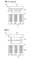
- Figures 2 and 3 show in a cross sectional view a comparison between (a) a known electromechanical transducer 240 comprising a rotor assembly 250 being equipped with Nd-Fe-B magnet pieces 254 having a certain content of Dy and (b) an electromechanical transducer 340 in accordance with an embodiment of the invention wherein Nd-Fe-B magnet pieces 354 are used which have a composition being free from the (very expensive) element Dy.
- stator assembly 245 has a stator support structure 247 comprising a stack of a plurality of lamination sheets and a plurality of stator windings 249 being accommodated within the stator support structure 247.
- the windings 249 are interconnected in a known manner by means of non depicted electrical connections.
- the rotor assembly 250 of the known electromechanical transducer 240 which is separated from the stator assembly 245 by an air gap ag, comprises a rotor support structure 252 providing the mechanical base for mounting the Nd-Fe-B PM pieces 254.
- the support structure 252 comprises a magnetic material in order to optimize the magnetic field generated by the Nd-Fe-B PM piece 254 and other Nd-Fe-B PM pieces not shown in Figure 2 .
- the magnetic field is optimized in such a manner that the magnetic field linkage between the stator assembly 245 and the rotor assembly 250 is maximized.
- a rotor assembly 350 of the electromechanical transducer 340 comprises a rotor support structure 352 providing the mechanical base for mounting the Nd-Fe-B PM pieces 354.
- the support structure 352 comprises a magnetic material in order to optimize the magnetic field linkage between the stator assembly 245 and the rotor assembly 350.
- the air gap ag between the rotor assembly 350 and the stator assembly 245 can be used for guiding a cooling fluid through the electromechanical transducer 340 in order to remove waste heat which during operation is generated in particular by the stator coils 249 of the stator assembly 245.
- a plurality of PM pieces can be mounted to the support structure 352.
- the PM pieces are preferably arranged in a matrix like structure around a curved surface area of the support structure 352 having a basically cylindrical geometry.
- Figure 3 for the sake of clarity only one PM piece 254 is depicted.
- the height h of the Nd-Fe-B PM piece 354 with 0% Dy is approximately larger by a factor of two compared to the height of the Nd-Fe-B PM piece 254 with x% Dy.
- the height which in Figures 2 and 3 extends along the vertical direction is oriented parallel to the magnetization direction of the Nd-Fe-B PM pieces 254, 354.
- the magnetic behavior can be kept at least approximately the same.
- the magnet height parallel to its magnetization direction has to be increased to end up with at least approximately the same magnet piece properties.
Landscapes
- Engineering & Computer Science (AREA)
- Power Engineering (AREA)
- Chemical & Material Sciences (AREA)
- Sustainable Development (AREA)
- Combustion & Propulsion (AREA)
- Crystallography & Structural Chemistry (AREA)
- Inorganic Chemistry (AREA)
- Life Sciences & Earth Sciences (AREA)
- General Engineering & Computer Science (AREA)
- Sustainable Energy (AREA)
- Mechanical Engineering (AREA)
- Electromagnetism (AREA)
- Physics & Mathematics (AREA)
- Dispersion Chemistry (AREA)
- Permanent Field Magnets Of Synchronous Machinery (AREA)
- Wind Motors (AREA)
- Hard Magnetic Materials (AREA)
- Connection Of Motors, Electrical Generators, Mechanical Devices, And The Like (AREA)
Priority Applications (7)
| Application Number | Priority Date | Filing Date | Title |
|---|---|---|---|
| EP12189269.9A EP2722855A1 (fr) | 2012-10-19 | 2012-10-19 | Aimant permanent de type Nd-Fe-B sans dysprosium, ensemble rotor, convertisseur électromécanique, éolienne |
| CA2830247A CA2830247A1 (fr) | 2012-10-19 | 2013-10-17 | Aimant permanent de type nd-fe-b avec dysporium, ensemble rotor, transducteur electromecanique et eolienne |
| US14/057,248 US20140110948A1 (en) | 2012-10-19 | 2013-10-18 | Nd-fe-b permanent magnet without dysprosium, rotor assembly, electromechanical transducer, wind turbine |
| BRBR102013026968-9A BR102013026968A2 (pt) | 2012-10-19 | 2013-10-18 | Imã permanente nd-fe-b sem disprósio, montagem de rotor, transdutor eletromecânico, turbina eólica |
| CN201310494040.1A CN103779036A (zh) | 2012-10-19 | 2013-10-21 | 不含镝的钕铁硼永磁体,转子组件,机电换能器,风力涡轮机 |
| KR1020130125471A KR20140050568A (ko) | 2012-10-19 | 2013-10-21 | 디스프로슘이 없는 Nd-Fe-B 영구 자석, 로터 조립체, 전자 기계식 트랜스듀서 및 풍력 터빈 |
| JP2013218050A JP2014086731A (ja) | 2012-10-19 | 2013-10-21 | Dyを含まないNd−Fe−B系永久磁石、ロータアセンブリ、電気機械式トランスデューサ、風車 |
Applications Claiming Priority (1)
| Application Number | Priority Date | Filing Date | Title |
|---|---|---|---|
| EP12189269.9A EP2722855A1 (fr) | 2012-10-19 | 2012-10-19 | Aimant permanent de type Nd-Fe-B sans dysprosium, ensemble rotor, convertisseur électromécanique, éolienne |
Publications (1)
| Publication Number | Publication Date |
|---|---|
| EP2722855A1 true EP2722855A1 (fr) | 2014-04-23 |
Family
ID=47137562
Family Applications (1)
| Application Number | Title | Priority Date | Filing Date |
|---|---|---|---|
| EP12189269.9A Withdrawn EP2722855A1 (fr) | 2012-10-19 | 2012-10-19 | Aimant permanent de type Nd-Fe-B sans dysprosium, ensemble rotor, convertisseur électromécanique, éolienne |
Country Status (7)
| Country | Link |
|---|---|
| US (1) | US20140110948A1 (fr) |
| EP (1) | EP2722855A1 (fr) |
| JP (1) | JP2014086731A (fr) |
| KR (1) | KR20140050568A (fr) |
| CN (1) | CN103779036A (fr) |
| BR (1) | BR102013026968A2 (fr) |
| CA (1) | CA2830247A1 (fr) |
Cited By (2)
| Publication number | Priority date | Publication date | Assignee | Title |
|---|---|---|---|---|
| WO2019207173A3 (fr) * | 2019-05-10 | 2020-04-02 | Siemens Gamesa Renewable Energy A/S | Fabrication d'aimant à flux focalisé faisant appel à une magnétisation changeante |
| EP4712112A1 (fr) * | 2024-09-11 | 2026-03-18 | Siemens Gamesa Renewable Energy A/S | Aimant permanent nd-fe-b avec cérium, ensemble rotor, transducteur électromécanique, éolienne |
Families Citing this family (8)
| Publication number | Priority date | Publication date | Assignee | Title |
|---|---|---|---|---|
| DE102015203841A1 (de) * | 2015-03-04 | 2016-09-08 | Wobben Properties Gmbh | Verfahren zum Betreiben einer Windenergieanlage |
| FR3051992A1 (fr) * | 2016-05-25 | 2017-12-01 | Valeo Equip Electr Moteur | Machine electrique tournante munie d'aimants en terre rare a faible taux de dysprosium |
| FR3051991B1 (fr) * | 2016-05-25 | 2018-07-06 | Valeo Equipements Electriques Moteur | Rotor de machine electrique tournante muni d'aimants en terre rare a faible taux de dysprosium |
| JP2018007313A (ja) * | 2016-06-27 | 2018-01-11 | 株式会社日立産機システム | 永久磁石モータおよびエレベータ駆動巻上機 |
| CN113508512A (zh) * | 2019-03-11 | 2021-10-15 | 西门子歌美飒可再生能源公司 | 包括具有不同磁畴对准模式的三个磁体装置的永磁体组件 |
| CN111834116B (zh) * | 2019-04-23 | 2025-03-28 | 西门子歌美飒可再生能源公司 | 制造具有减小的变形的烧结永磁体 |
| CN111834117B (zh) * | 2019-04-23 | 2025-04-04 | 西门子歌美飒可再生能源公司 | 利用具有不对称形成的磁装置的设备制造烧结磁通聚焦永磁体 |
| CN115662772B (zh) * | 2022-10-13 | 2026-04-21 | 安徽省瀚海新材料股份有限公司 | 一种改善高矫顽力坯料材料脆性的方法 |
Citations (3)
| Publication number | Priority date | Publication date | Assignee | Title |
|---|---|---|---|---|
| JP2002153036A (ja) * | 2000-11-08 | 2002-05-24 | Sumitomo Special Metals Co Ltd | 回転機およびそれを用いた風力発電機 |
| EP1830451A1 (fr) * | 2004-12-17 | 2007-09-05 | Hitachi Metals, Ltd. | Rotor pour moteur et son procede de fabrication |
| EP2131478A1 (fr) * | 2007-03-23 | 2009-12-09 | Shin-Etsu Chemical Co., Ltd. | Générateur à aimant permanent et générateur d'éolienne l'utilisant |
Family Cites Families (13)
| Publication number | Priority date | Publication date | Assignee | Title |
|---|---|---|---|---|
| JPH07169618A (ja) * | 1993-12-15 | 1995-07-04 | Daido Steel Co Ltd | 大型ラジアル異方性リング形状永久磁石およびその製造方法 |
| US6136100A (en) * | 1999-09-29 | 2000-10-24 | Magnequench International, Inc. | Rare-earth alloy powders for magnets and process for making magnets from rare-earth alloy powders |
| JP4391897B2 (ja) * | 2004-07-01 | 2009-12-24 | インターメタリックス株式会社 | 磁気異方性希土類焼結磁石の製造方法及び製造装置 |
| JP4376863B2 (ja) * | 2005-12-22 | 2009-12-02 | シナノケンシ株式会社 | 永久磁石型回転機 |
| JP4924615B2 (ja) * | 2006-11-30 | 2012-04-25 | 日立金属株式会社 | R−Fe−B系微細結晶高密度磁石およびその製造方法 |
| CN101641856A (zh) * | 2007-03-23 | 2010-02-03 | 信越化学工业株式会社 | 永磁式发电机及使用它的风力发电机 |
| CN101409121B (zh) * | 2008-08-05 | 2011-01-05 | 中钢集团安徽天源科技股份有限公司 | 电机用钕铁硼永磁体及其制造方法 |
| US8405236B2 (en) * | 2009-04-21 | 2013-03-26 | Juan V. David | Brushless DC turbo-hydro electric generator |
| US20110074530A1 (en) * | 2009-09-30 | 2011-03-31 | General Electric Company | Mixed rare-earth permanent magnet and method of fabrication |
| CN102456458B (zh) * | 2010-10-15 | 2017-02-08 | 中国科学院宁波材料技术与工程研究所 | 高耐蚀性烧结钕铁硼磁体及其制备方法 |
| US9468972B2 (en) * | 2011-09-30 | 2016-10-18 | Gm Global Technology Operations, Llc | Method of making Nd—Fe—B sintered magnets with reduced dysprosium or terbium |
| CN102436893B (zh) * | 2011-12-15 | 2016-04-27 | 钢铁研究总院 | 一种无Tb少Dy的高矫顽力磁体及制备方法 |
| US20130266473A1 (en) * | 2012-04-05 | 2013-10-10 | GM Global Technology Operations LLC | Method of Producing Sintered Magnets with Controlled Structures and Composition Distribution |
-
2012
- 2012-10-19 EP EP12189269.9A patent/EP2722855A1/fr not_active Withdrawn
-
2013
- 2013-10-17 CA CA2830247A patent/CA2830247A1/fr not_active Abandoned
- 2013-10-18 BR BRBR102013026968-9A patent/BR102013026968A2/pt not_active IP Right Cessation
- 2013-10-18 US US14/057,248 patent/US20140110948A1/en not_active Abandoned
- 2013-10-21 CN CN201310494040.1A patent/CN103779036A/zh active Pending
- 2013-10-21 JP JP2013218050A patent/JP2014086731A/ja active Pending
- 2013-10-21 KR KR1020130125471A patent/KR20140050568A/ko not_active Withdrawn
Patent Citations (3)
| Publication number | Priority date | Publication date | Assignee | Title |
|---|---|---|---|---|
| JP2002153036A (ja) * | 2000-11-08 | 2002-05-24 | Sumitomo Special Metals Co Ltd | 回転機およびそれを用いた風力発電機 |
| EP1830451A1 (fr) * | 2004-12-17 | 2007-09-05 | Hitachi Metals, Ltd. | Rotor pour moteur et son procede de fabrication |
| EP2131478A1 (fr) * | 2007-03-23 | 2009-12-09 | Shin-Etsu Chemical Co., Ltd. | Générateur à aimant permanent et générateur d'éolienne l'utilisant |
Non-Patent Citations (1)
| Title |
|---|
| STANDARD: "NdFeB Magnets / Neodymium Iron Boron Magnets Datasheet", 1 January 2012 (2012-01-01), XP055434951, Retrieved from the Internet <URL:https://www.eclipsemagnetics.com/media/wysiwyg/datasheets/magnet_materials_and_assemblies/ndfeb_neodymium_iron_boron-standard_ndfeb_range_datasheet_rev1.pdf> [retrieved on 20171213] * |
Cited By (2)
| Publication number | Priority date | Publication date | Assignee | Title |
|---|---|---|---|---|
| WO2019207173A3 (fr) * | 2019-05-10 | 2020-04-02 | Siemens Gamesa Renewable Energy A/S | Fabrication d'aimant à flux focalisé faisant appel à une magnétisation changeante |
| EP4712112A1 (fr) * | 2024-09-11 | 2026-03-18 | Siemens Gamesa Renewable Energy A/S | Aimant permanent nd-fe-b avec cérium, ensemble rotor, transducteur électromécanique, éolienne |
Also Published As
| Publication number | Publication date |
|---|---|
| BR102013026968A2 (pt) | 2014-08-19 |
| KR20140050568A (ko) | 2014-04-29 |
| US20140110948A1 (en) | 2014-04-24 |
| JP2014086731A (ja) | 2014-05-12 |
| CN103779036A (zh) | 2014-05-07 |
| CA2830247A1 (fr) | 2014-04-19 |
Similar Documents
| Publication | Publication Date | Title |
|---|---|---|
| EP2722855A1 (fr) | Aimant permanent de type Nd-Fe-B sans dysprosium, ensemble rotor, convertisseur électromécanique, éolienne | |
| US9379583B2 (en) | Magnet assembly | |
| JP5060546B2 (ja) | 永久磁石式発電機とそれを用いた風力発電機 | |
| CN101401284B (zh) | 电机,特别是发电机 | |
| EP2490319A1 (fr) | Moteur à coupure axiale | |
| EP2806538A1 (fr) | Procédé de fabrication de rotor de moteur à aimant permanent | |
| CN101641856A (zh) | 永磁式发电机及使用它的风力发电机 | |
| CN101702558A (zh) | 盘式永磁风力发电机 | |
| JP2013519044A (ja) | 垂直軸盤式発電機用磁気浮上支持構造とそれを用いた垂直軸盤式発電機 | |
| CN103795202A (zh) | 轴向磁通的多定子/转子结构新型风力发电机 | |
| US10505405B2 (en) | Electric machine having a rotor with first and second permanent magnets in different regions with different temperature ranges | |
| JP5594660B2 (ja) | リラクタンス発電機 | |
| Ocak et al. | Performance aspects and verifications of in-runner and out-runner permanent magnet synchronous generator designs of the same magnet structure for low speed wind systems | |
| JP4357856B2 (ja) | 風力発電機 | |
| EP2879281A1 (fr) | Machine électrique rotative à aimant permanent et système de génération d'énergie éolienne | |
| EP4712112A1 (fr) | Aimant permanent nd-fe-b avec cérium, ensemble rotor, transducteur électromécanique, éolienne | |
| CN201541188U (zh) | 盘式永磁风力发电机 | |
| US20180019629A1 (en) | Radial Flux Alternator | |
| CN101005230B (zh) | 一种多极内转子式永磁发电机 | |
| Msc | Direct-drive wind turbines | |
| JP4500182B2 (ja) | 電動機の分割型固定子 | |
| EP2605371B1 (fr) | Pièce de composant magnétique comportant différents matériaux magnétiques |
Legal Events
| Date | Code | Title | Description |
|---|---|---|---|
| PUAI | Public reference made under article 153(3) epc to a published international application that has entered the european phase |
Free format text: ORIGINAL CODE: 0009012 |
|
| AK | Designated contracting states |
Kind code of ref document: A1 Designated state(s): AL AT BE BG CH CY CZ DE DK EE ES FI FR GB GR HR HU IE IS IT LI LT LU LV MC MK MT NL NO PL PT RO RS SE SI SK SM TR |
|
| AX | Request for extension of the european patent |
Extension state: BA ME |
|
| 17P | Request for examination filed |
Effective date: 20140417 |
|
| RBV | Designated contracting states (corrected) |
Designated state(s): AL AT BE BG CH CY CZ DE DK EE ES FI FR GB GR HR HU IE IS IT LI LT LU LV MC MK MT NL NO PL PT RO RS SE SI SK SM TR |
|
| RAP1 | Party data changed (applicant data changed or rights of an application transferred) |
Owner name: SIEMENS AKTIENGESELLSCHAFT |
|
| 17Q | First examination report despatched |
Effective date: 20171220 |
|
| STAA | Information on the status of an ep patent application or granted ep patent |
Free format text: STATUS: THE APPLICATION IS DEEMED TO BE WITHDRAWN |
|
| 18D | Application deemed to be withdrawn |
Effective date: 20180501 |