EP2722937B1 - Ensemble connecteur - Google Patents
Ensemble connecteur Download PDFInfo
- Publication number
- EP2722937B1 EP2722937B1 EP12799825.0A EP12799825A EP2722937B1 EP 2722937 B1 EP2722937 B1 EP 2722937B1 EP 12799825 A EP12799825 A EP 12799825A EP 2722937 B1 EP2722937 B1 EP 2722937B1
- Authority
- EP
- European Patent Office
- Prior art keywords
- plug
- socket
- terminal
- holder
- terminals
- Prior art date
- Legal status (The legal status is an assumption and is not a legal conclusion. Google has not performed a legal analysis and makes no representation as to the accuracy of the status listed.)
- Active
Links
Images






Classifications
-
- H—ELECTRICITY
- H01—ELECTRIC ELEMENTS
- H01R—ELECTRICALLY-CONDUCTIVE CONNECTIONS; STRUCTURAL ASSOCIATIONS OF A PLURALITY OF MUTUALLY-INSULATED ELECTRICAL CONNECTING ELEMENTS; COUPLING DEVICES; CURRENT COLLECTORS
- H01R13/00—Details of coupling devices of the kinds covered by groups H01R12/70 or H01R24/00 - H01R33/00
- H01R13/40—Securing contact members in or to a base or case; Insulating of contact members
- H01R13/42—Securing in a demountable manner
-
- H—ELECTRICITY
- H01—ELECTRIC ELEMENTS
- H01R—ELECTRICALLY-CONDUCTIVE CONNECTIONS; STRUCTURAL ASSOCIATIONS OF A PLURALITY OF MUTUALLY-INSULATED ELECTRICAL CONNECTING ELEMENTS; COUPLING DEVICES; CURRENT COLLECTORS
- H01R13/00—Details of coupling devices of the kinds covered by groups H01R12/70 or H01R24/00 - H01R33/00
- H01R13/40—Securing contact members in or to a base or case; Insulating of contact members
- H01R13/42—Securing in a demountable manner
- H01R13/436—Securing a plurality of contact members by one locking piece or operation
- H01R13/4364—Insertion of locking piece from the front
-
- H—ELECTRICITY
- H01—ELECTRIC ELEMENTS
- H01R—ELECTRICALLY-CONDUCTIVE CONNECTIONS; STRUCTURAL ASSOCIATIONS OF A PLURALITY OF MUTUALLY-INSULATED ELECTRICAL CONNECTING ELEMENTS; COUPLING DEVICES; CURRENT COLLECTORS
- H01R13/00—Details of coupling devices of the kinds covered by groups H01R12/70 or H01R24/00 - H01R33/00
- H01R13/46—Bases; Cases
- H01R13/502—Bases; Cases composed of different pieces
-
- H—ELECTRICITY
- H01—ELECTRIC ELEMENTS
- H01R—ELECTRICALLY-CONDUCTIVE CONNECTIONS; STRUCTURAL ASSOCIATIONS OF A PLURALITY OF MUTUALLY-INSULATED ELECTRICAL CONNECTING ELEMENTS; COUPLING DEVICES; CURRENT COLLECTORS
- H01R24/00—Two-part coupling devices, or either of their cooperating parts, characterised by their overall structure
- H01R24/86—Parallel contacts arranged about a common axis
Definitions
- the present invention relates to a connector assembly, particularly to a high frequency connector including a shield function of being able to prevent an external noise and an internal noise of a high frequency signal in a high frequency band.
- a plug connector for a conductor which connects a multi-core individual conductor in which one end is firmly coupled to a pin contact or a socket contact.
- the connector consists of a pin contact or socket contact including an individual conductor inserted in a contact chamber , which is oriented along a retention body and opened halfway, the retention body is inserted in a connector sleeve surrounding the retention body , the connector sleeve is constructed by a first connector portion and a second connector portion , both the connector portions are disposed on a retention sleeve opened on both sides, and the pin contact or socket contact oriented in the contact chamber of the retention body (30) is fixed using a longitudinal rib (24) properly disposed in the retention sleeve.
- an electrical connector includes an outer shell having a cavity formed therein and a front dielectric member having a base portion and an insulating sleeve extending from the base portion.
- the base portion has contact passages formed therein that extend between front and rear ends of the base portion, wherein the contact passages are configured to receive contacts.
- the electrical connector also includes a rear dielectric member having open sided contact passages extending between front and rear ends of the rear dielectric member. The contact passages are configured to receive the contacts such that at least a portion of the contacts are exposed laterally through open sides of the contact passages. The front end of the rear dielectric member is inserted at least partially into the insulating sleeve.
- US 2003/199205 A1 teaches contacts that are terminated to the front ends of wires are rapidly mounted in a connector shell while assuring reliable separation of the contacts. After each contact is terminated to the front end of a wire, the contact is laid in a slot of an insulative retainer. The retainer is then inserted forwardly between top and bottom arms of the rear portion of an insulative body, while the contacts project into passages in the front portion of the body.
- the assembly of retainer and body is inserted into the shell that has a cylindrical inner surface that radially positions the retainer between the arms of the body.;
- a crimp barrel is moved forwardly into the shell to about the rear of the retainer, a braiding of a cable that contains the wires is folded back around the crimp barrel, and the rear portion of the shell is crimped around the braiding and crimp barrel.
- the contact holder for electrical plug-in connections known form DE 20 2005 017981 U1 has an insulating body. It has an insulating body ring connected to an insulating body housing with openings for contact pins in its flat end. There is a contact carrier, with an inner carrier with U-section holders fitting inside an outer carrier with more U-section holders.
- the pin contact is connected to a lead wire of a cable and is supported by the retention body while assembled one by one from an outer circumferential surface side. Therefore, unfortunately, the positions of the pin contacts are easily deviated from each other in an axial center direction, a desired high frequency property is hardly obtained, and it takes a lot of time to adjust the positions of the pin contacts.
- a problem of the present invention is to provide a connector assembly, in which the positioning of the terminal is accurately and easily performed and the desired high frequency property is obtained.
- the inventor obtained knowledge that the desired high frequency property is obtained when the position deviation between the terminals is eliminated in the axial center direction, and completed the present invention based on the knowledge.
- the connector assembly has a configuration in accordance with claim 1. Further improvements are subject to the dependent claims.
- the position of the terminal can be controlled in the axial center direction through the terminal holder, and the position deviation in the axial center direction can be eliminated, thereby obtaining the connector having the desired high frequency property.
- the positions of the plurality of terminals can simultaneously be controlled through the terminal holder, and the positioning in the axial center direction is accurately and easily performed, thereby obtaining the connector having the good assembly workability.
- the position of the terminal can be controlled in the axial center direction through the socket terminal holder, and the position deviation in the axial center direction can be eliminated, thereby obtaining the connector having the desired high frequency property.
- the positions of the plurality of socket terminals can simultaneously be controlled through the socket terminal holder, and the positioning in the axial center direction is accurately and easily performed, thereby obtaining the connector having the good assembly workability.
- a position of one end portion of the plug terminal is controlled by sandwiching the one end portion of the plug terminal between the plug body and the plug terminal holder.
- the position of the terminal can be controlled in the axial center direction through the plug terminal holder, and the position deviation in the axial center direction can be eliminated, thereby obtaining the connector having the desired high frequency property.
- the positions of the plurality of terminals can simultaneously be controlled through the plug terminal holder, and the positioning in the axial center direction is accurately and easily performed, thereby obtaining the connector having the good assembly workability.
- a plurality of plug terminals protrude from the plug body and include an equal protrusion length
- a plurality of socket terminals protrude from the socket body and include an equal protrusion length.
- the protrusion dimensions of the plurality of plug terminals or the plurality of socket terminals are equalized in the axial center direction, thereby obtaining the connector having the good high frequency property.
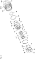
- a connector assembly according to an embodiment of the present invention will be described with reference to Figs. 1(A) to 11(B) .
- a connector includes a bayonet plug 10 and a bayonet socket 60.
- the bayonet plug 10 includes a plug body 11, a total of eight plug terminals 20 including four sets of two plug terminals 20, a plug terminal holder 25, a shield member 30, a cylindrical housing 40, a fastening tool 47, a ring cover 50, a coil spring 51, a stopper tool 52, and a plug holder 55.
- the plug body 11 is a step columnar resin molding including a large diameter portion 12, and a set of two terminal holes 14 is made in each of four areas that are partitioned by a cross slit 13 provided along an axial center.
- At least one of PBT (polybutylene terephthalate), LCP (liquid crystal polymer), and PPS (polyphenylene sulfide) can be used as a material for the plug body 11.
- a fitting recess 15 in which the plug terminal holder 25 to be described later can be fitted is provided in an end face of the large diameter portion 12 (see Fig. 4 ).
- a pin terminal portion 21 that is of a transmission line portion inserted in the terminal hole 14 of the plug body 11 is provided on one end side of the plug terminal 20 while a connection portion 23 is provided on the other end side with a circular step portion 22 interposed there between.
- a lead wire 101 of an electric signal cable 100 to be described later can be electrically connected to the connection portion 23.
- the eight lead wires 101 are coated with an insulating resin in units of a set of two lead wires 101, and also coated with an aluminum foil (not illustrated) and a mesh shield line (not illustrated).
- the lead wire 101 is electrically connected to the connection portion 23 of the plug terminal 20 by pressure bonding and/or soldering (see Figs. 9(A) to 10 ).
- the plug terminal holder 25 has an outer circumferential shape that can be fitted in the fitting recess 15 of the plug body 11, and a set of two terminal notch holes 27 is made in each of four areas that are partitioned by a cross slit 26 provided along the axial center.
- the terminal notch hole 27 has a sectional shape that is fitted in an end portion of the connection portion 23 of the plug terminal 20 to be able to control a position in the axial center direction (see Figs. 9(A) and 10 ).
- the shield member 30 is a molding made of a step cylindrical conductive member including a large diameter portion 31, and partitioned into four spatial areas by a cross partition wall 32 provided along the axial center.
- a guiding ridge 33 is provided in a center portion of the cross partition wall 32.
- a circular groove portion 34 with which a conductive C-ring 36 can be engaged is provided in the outer circumferential surface of the shield member 30, and a circular groove portion 35 with which an elastic a-ring 37 can be engaged is provided in the outer circumferential surface of the large diameter portion 31.
- the conductive C-ring 36 has a sectional shape that not only is engaged with the circular groove portion 34 to electrically connect the plug holder 55 (to be described later) and the shield member 30, but also can stop the plug holder 55.
- the cylindrical housing 40 is a molding.
- the molding has a sectional shape in which the shield member 30, having the plug body 11 disposed therein, can be accommodated.
- the molding comprises a cylindrical conductive member including a small diameter portion 41.
- An external thread portion 40a is provided in an outer circumferential surface edge portion on one end side of the cylindrical housing 40, and an external thread portion 41 a is formed in the outer circumferential surface of the small diameter portion 41.
- a positioning first circular step portion 42, a positioning second circular step portion 43, and a positioning third circular step portion 44 are provided in an inner circumferential surface of the cylindrical housing 40.
- the shield member 30 can be stopped by screwing the ring cover 50 on the external thread portion 40a.
- a water-proof bush 45 and a cable clamp 46 are elastically deformed by screwing the fastening tool 47 on the external thread portion 41 a, which allows the electric signal cable 100 to be stopped.
- the coil spring 51 has an inner diameter such that the shield member 30 can be fitted, and the coil spring 51 can be brought into contact with the stopper tool 52 to be described later with a pressure to bias the stopper tool 52 outward.
- the stopper tool 52 has a ring shape having such an inner diameter that the outer circumferential surface of the shield member 30 can be fitted, and three engagement claws 53 are protruded in parallel to the axial center with equal intervals therebetween.
- An engagement protrusion 54 is provided in each of leading end portions of the outer circumferential surfaces of the engagement claws 53.
- the plug holder 55 has such a cylindrical shape as to rotatably fit to the shield member 30.
- an external thread portion 56 is formed in a half of the outer circumferential surface on one end side, and a turning operation circular rib 57 extends from the edge portion of the outer circumferential surface on one end side.
- a positioning mark 55a is provided in the edge portion on the other end side of the turning operation circular rib 57.
- Three guide grooves 58 which are communicated along the outer circumferential surface of the plug holder 55 and the inner circumferential surface of the turning operation circular rib 57 are formed in parallel to the axial center with equal intervals therebetween.
- the engagement claw 53 of the stopper tool 52 can be inserted in each of the guide grooves 58.
- An external thread portion 59 is provided on the other end side of each of the guide grooves 58 in order to ensure an effective length of a screw.
- the lead wires 101 of the electric signal cable 100 are electrically connected to the respective connection portions 23 of the plug terminals 20.
- the connection portions 23 of the plug terminals 20 are assembled in the terminal notch holes 27 of the plug terminal holder 25 by the fitting, the pin terminal portions 21 of the plug terminals 20 are inserted in the respective terminal holes 14 of the plug body 11, and the plug terminal holder 25 is fitted in the fitting recess 15 of the plug body 11. Therefore, the leading ends of the pin terminal portions 21 protrude from the plug body 11.
- the plug body 11 is assembled in the shield member 30 in which the elastic O-ring 37 is mounted on the circular groove portion 35 of the large diameter portion 31.
- the ring cover 50, the coil spring 51, the stopper tool 52, and the plug holder 55 are sequentially assembled in the shield member 30.
- the conductive C-ring 36 is engaged with the circular groove portion 34 while the plug holder 55 is pressed inwardly to compress the coil spring 51, thereby obtaining a semifinished-product plug 10.
- the semifinished-product plug 10 is assembled in the cylindrical housing 40, and the cylindrical housing 40 is sealed by screwing the ring cover 50 on the external thread portion 40a of the cylindrical housing 40.
- the fastening tool 47 is screwed on the external thread portion 41 a of the cylindrical housing 40, and the water-proof bush 45 and the clamp 46 in which the electric signal cable 100 is inserted are elastically deformed to fix the electric signal cable 100, thereby completing the assembly of the plug 10.
- a continuous cylindrical air gap is formed between the outer circumferential surface of the pin terminal portion 21 of the plug terminal 20 and the inner circumferential surface of the terminal hole 14 of the plug body 11.
- the ring cover 50 is screwed on the cylindrical housing 40 to fasten the plug body 11, the plug terminal holder 25, and the shield member 30 in the axial center direction. Therefore, even if the assembly positions in the axial center direction vary in the plug terminals 20, the plug terminal holder 25 presses the connection portions 23 of the plug terminals 20 onto the side of the plug body 11 to eliminate the variation of the assembly position. As a result, advantageously the plurality of plug terminals 20 protruding from the plug body 11 in the axial center direction can be equalized to each other in protrusion dimension.
- the aluminum foil (not illustrated) and the mesh shield line (not illustrated) of the electric signal cable 100 are in contact with the cylindrical housing 40. Therefore, a shield structure is formed through the cylindrical housing 40, the ring cover 50, the shield member 30, the conductive C-ring 36, and the plug holder 55.
- the bayonet socket 60 is used while attached to an attaching plate (not illustrated), and the bayonet socket 60 includes a socket body 61, socket terminals 70, a shield member 80, and a socket holder 90.
- the socket body 61 is a step columnar resin molding including a large diameter portion 62, and a set of two terminal holes 64 is made in each of four areas that are partitioned by a cross slit 63 provided along the axial center.
- a guiding groove portion 65 is provided in the center portion of the cross slit 63.
- At least one of PBT (polybutylene terephthalate), LCP (liquid crystal polymer), and PPS (polyphenylene sulfide) can be used as a material for the socket body 61.
- a circular groove portion 66 is provided in the outer circumferential surface of the large diameter portion 62, and a notch groove 67 is provided in the edge portion of the outer circumferential surface of the large diameter portion 62.
- a large-diameter elastic O-ring 68 is mounted on the circular groove portion 66 of the large diameter portion 62, and a small-diameter elastic O-ring 69 is mounted on a base portion of the large diameter portion 62
- the socket terminal 70 has a shape that can be inserted in the terminal hole 64 of the socket body 61, and circular step portions 72 and 72 are provided at both ends of a transmission line portion 71.
- a socket portion 73 in which the pin terminal portion 21 of the plug terminal 20 can be inserted is provided on one end side of one of the circular step portions 72 and 72, and a connection portion 74 electrically connected to a circuit board (not illustrated) is provided on the other end side of the other circular step portion 72.
- the shield member 80 is formed by a partition wall 81 having a cross shape in section and a cap portion 82.
- the partition wall 81 can be inserted in the cross slit 63 of the socket body 61, and the cap portion 82 is integrally molded on one end side of the partition wall 81.
- a positioning protrusion 84 protrudes from an outward-looking surface of the cap portion 82.
- a substantially square conductive C-ring 85 can be latched in a circular engagement groove 83 provided in the outer circumferential surface of the cap portion 82.
- the socket holder 90 of Fig. 5 is made of metal, and has a cylindrical shape in which the socket body 61 can be accommodated.
- An external thread portion 92 is formed on one side of a hexagonal fixing rib 91 provided in the substantial center of the outer circumferential surface of the socket holder 90, and a positioning mark 90a is provided in the edge portion on the other side of the fixing rib 91.
- a nut 95 is screwed on the external thread portion 92 in order to fix the attaching plate (not illustrated) with an elastic O-ring 94 (see Figs. 9(A) to 9(C) ) interposed therebetween.
- a fixing internal thread portion 96 is formed, and the fixing internal thread portion 96 is notched to form a substantial L-shape engagement groove 97.
- the socket holder is not necessarily fixed to the attaching plate, but the electric signal cable 100 may directly be connected.
- the socket terminals 70 are press-fitted in the respective terminal holes 64 of socket body 61.
- the conductive C-ring 85 is latched in the engagement groove 83 of the shield member 80 while the large-diameter and small-diameter elastic a-rings 68 and 69 are mounted on the socket body 61.
- the cross partition wall 81 of the shield member 80 is fitted in the cross slit 63 of the socket body 61.
- the socket body 61 is fitted in the socket holder 90, and the large-diameter elastic a-ring 68 is press-fitted while elastically deformed, and the cap portion 82 of the shield member 80 is press-fitted in the inner circumferential surface of the socket holder 90, thereby completing the assembly of the socket holder 90. Therefore, the large-diameter elastic O-ring 68 is elastically deformed to establish the sealing, and electric conduction is established between the shield member 80 and the socket holder 90 through the conductive C-ring 85 to form a shield structure.
- the continuous cylindrical air gap is formed between the outer circumferential surface of the transmission line portion 71 of the socket terminal 70 and the inner circumferential surface of the terminal hole 64 of the socket 60.
- FIG. 1(A) to 2(B) A method for connecting the bayonet plug 10 and the bayonet socket 60 will be described below.
- the guiding ridge 33 of the cross partition wall 32 provided in the shield member 30 of the plug 10 is positioned and pressed in the guiding groove portion 65 of the cross slit 63 of the socket body 61. Therefore, the pin terminal portions 21 of the plug terminals 20 are inserted in and electrically connected to the socket portions 73 of the socket terminals 70.
- the engagement claw 53 of the stopper tool 52 biased outward by the spring force of the coil spring 51 is inserted in the substantial L-shape engagement groove 97 provided in the inner circumferential surface of the socket holder 90.
- the engagement protrusion 54 of the engagement claw 53 is slid along and engaged with the substantial L-shape engagement groove 97, the positioning marks 55a and 90a are matched with each other to form a locked state.
- the outer circumferential edge portion of the leading end surface of the shield member 30 compresses and elastically deforms the elastic O-ring 69, which allows a high waterproof property to be ensured.
- socket body 61 is mounted on the socket holder 90, preferably, a slight play is provided in the axial center direction with respect to the socket body 61.
- the invention can be applied to the bayonet plug 10 and the bayonet socket 60.
- the present invention may be applied to a conventional screw type socket and a conventional screw type plug.
- the bayonet socket 60 is connected to the bayonet plug 10.
- the conventional screw type plug may be connected to the bayonet socket 60 of the embodiment, or the bayonet socket 10 of the embodiment may be connected to the conventional screw type plug.
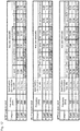
- the plug body and the socket body were made of PBT (polybutylene terephthalate), LCP (liquid crystal polymer), and PPS (polyphenylene sulfide), respectively, and an insertion loss was analyzed in the case that the dimension of the continuous cylindrical air gap formed between the outer circumferential surface of the terminal and the inner circumferential surface of the terminal hole varied. Whether the insertion loss was smaller than a specification value in category 7 (a frequency band of 1 to 600 MHz) was analyzed based on a test standard of IEG 60512-25-2.
- Fig. 12 illustrates tables of analysis results
- Figs. 13 to 15 illustrate graphs of the detailed analysis results.
- the insertion loss is less than or equal to the specification value of 0.49 dB to thus satisfy the requirement of category 7 when the dimension of the cylindrical air gap is greater than or equal to 0.075 mm even at a transmission frequency of 600 MHz. Accordingly, it is clear that a desired high frequency property is obtained only by providing the cylindrical air gap having a thickness of 0.075 mm or more in the outer circumferential surface of the terminal transmission line.
- the high frequency property was analyzed in the case that the plug terminals adjacent to each other were deviated by 1 mm in the axial center direction.
- Fig. 16(A) for example, it was assumed that equilibrium occurred where deviation did not exist in the axial center direction between a differential pair 1/2 and an adjacent differential pair 3/4, and it was assumed that non-equilibrium occurred where the deviation of 1 mm existed in the axial center direction between the differential pair 1/2 and the adjacent differential pair 3/4.
- a near-end crosstalk was analyzed at the transmission frequency of 600 MHz.
- a relationship between the differential pair 1/2 and a differential pair 5/6 and a relationship between the differential pair 1/2 and a differential pair 7/8 were analyzed.
- Fig. 16(B) illustrates analysis results
- Figs. 17 to 19 illustrate graphs of the detailed analysis results.
- the socket and the plug are directly electrically connected to each other on the identical axial center.
- the present invention can also be applied to the case that the electric cable is connected to the socket which is previously fixed to the attaching plate with the plug interposed there between.
Landscapes
- Details Of Connecting Devices For Male And Female Coupling (AREA)
- Coupling Device And Connection With Printed Circuit (AREA)
- Connector Housings Or Holding Contact Members (AREA)
Claims (5)
- Ensemble connecteur comprenant une prise (10) et une douille (60),
la prise (10) comprenant une pluralité de bornes de prise (20), un corps de prise (11), un support de prise (55), un élément de blindage (30), un boîtier cylindrique (40) et un couvercle annulaire (50) ;
chaque borne de prise (20) de la prise (10) pouvant être connectée à une première ligne de signal électrique respective et une partie d'extrémité (21) de chaque borne de prise (20) pouvant être insérée dans un trou de borne (14) du corps de prise (11) ;
l'élément de blindage (30) présentant le corps de prise (11) assemblé à l'intérieur ;
le boîtier cylindrique (40) recevant l'élément de blindage (30) ;
le couvercle annulaire (50) configuré pour se visser sur le boîtier cylindrique (40) ;
le support de prise (55) configuré pour s'ajuster sur l'élément de blindage (30) ;
la douille (60) comprenant une pluralité de bornes de douille (70), un corps de douille (61) et un support de douille (90)
chaque borne de douille (70) de la douille (60) pouvant être connectée à une seconde ligne de signal électrique respective et pouvant être insérée dans un trou de borne (64) du corps de douille (61) ;
dans lequel le support de prise (55) et le support de douille (90) sont configurés pour être connectés l'un à l'autre ;
dans lequel chaque borne de prise (20) est configurée pour être ajustée par pression dans et peut être connectée électriquement à l'une de la pluralité de bornes de douille (70) ;
dans lequel la prise (10) comprend un support de borne de prise (25), le support de borne de prise (25) présentant une forme circonférentielle extérieure configurée pour s'ajuster dans un évidement d'ajustement (15) du corps de prise (11) ;
dans lequel le support de borne de prise est fait d'un matériau isolant,
dans lequel une partie de connexion (23) de chaque borne de prise (20) est ajustée et maintenue axialement dans un trou d'encoche de borne (27) du support de borne de prise (25), et la partie de connexion (23) de chaque borne de prise (20) est configurée pour être connectée électriquement à la première ligne de signal électrique respective,
dans lequel une position de chacune de la pluralité des bornes de prise (20) dans une direction de centre axial est commandée en ajustant la partie de connexion (23) de chacune de la pluralité de bornes de prise (20) dans le support de borne de prise (25), et le couvercle annulaire (50) est configuré pour se visser sur le boîtier cylindrique (40) pour fixer le corps de prise (11), le support de borne de prise (25), et l'élément de blindage (30) dans la direction de centre axial de sorte que le support de borne de prise (25) presse la partie de connexion (23) de chacune de la pluralité des bornes de prise (20) sur un côté du corps de prise (11), en éliminant ainsi un écart de position entre les bornes de prise (20) dans la direction de centre axial. - Ensemble connecteur selon la revendication 1, dans lequel la pluralité de bornes de prise (20) contient des parties qui font saillie depuis le corps de prise (11) et inclut une longueur de saillie égale.
- Ensemble connecteur selon la revendication 1 ou 2, dans lequel la pluralité de bornes de douille (70) fait saillie depuis le corps de douille (61) et inclut une longueur de saillie égale.
- Ensemble connecteur selon l'une quelconque des revendications 1 à 3, dans lequel l'un parmi le corps de prise (11) et le corps de douille (61) est fait d'au moins l'un parmi un polybutylène téréphtalate, un polymère à cristaux liquides, et un sulfure de polyphénylène.
- Ensemble connecteur selon l'une des revendications 1 à 4,
dans lequel l'ensemble de trous d'encoche de borne (27) sont divisés par une fente transversale (26) le long d'un centre axial,
dans lequel un écart de position entre les bornes de prise (20) adjacentes les unes aux autres est configuré pour être inférieur à 1 mm dans la direction de centre axial.
Applications Claiming Priority (2)
| Application Number | Priority Date | Filing Date | Title |
|---|---|---|---|
| JP2011133531A JP5024473B1 (ja) | 2011-06-15 | 2011-06-15 | コネクタ |
| PCT/JP2012/056570 WO2012172845A1 (fr) | 2011-06-15 | 2012-03-14 | Connecteur |
Publications (3)
| Publication Number | Publication Date |
|---|---|
| EP2722937A1 EP2722937A1 (fr) | 2014-04-23 |
| EP2722937A4 EP2722937A4 (fr) | 2014-10-22 |
| EP2722937B1 true EP2722937B1 (fr) | 2020-09-02 |
Family
ID=46980549
Family Applications (1)
| Application Number | Title | Priority Date | Filing Date |
|---|---|---|---|
| EP12799825.0A Active EP2722937B1 (fr) | 2011-06-15 | 2012-03-14 | Ensemble connecteur |
Country Status (5)
| Country | Link |
|---|---|
| US (1) | US9806451B2 (fr) |
| EP (1) | EP2722937B1 (fr) |
| JP (1) | JP5024473B1 (fr) |
| CN (1) | CN103797652B (fr) |
| WO (1) | WO2012172845A1 (fr) |
Cited By (1)
| Publication number | Priority date | Publication date | Assignee | Title |
|---|---|---|---|---|
| US20220200205A1 (en) * | 2020-12-18 | 2022-06-23 | Webasto Charging Systems, Inc. | Electrical connector assembly |
Families Citing this family (47)
| Publication number | Priority date | Publication date | Assignee | Title |
|---|---|---|---|---|
| DE202012008970U1 (de) | 2012-09-18 | 2012-10-17 | Rosenberger Hochfrequenztechnik Gmbh & Co. Kg | Steckverbinder |
| US9236688B2 (en) * | 2013-02-15 | 2016-01-12 | Tyco Electronics Services Gmbh | Electrical connectors having differential pairs |
| CN104116604A (zh) * | 2013-04-25 | 2014-10-29 | 苏州大学附属第一医院 | 一种多头端子机构 |
| US9102088B2 (en) * | 2013-08-20 | 2015-08-11 | Sabritec | Molded insulator |
| JP6335075B2 (ja) * | 2014-09-05 | 2018-05-30 | タイコエレクトロニクスジャパン合同会社 | コネクタ |
| CN105896201A (zh) * | 2014-11-10 | 2016-08-24 | 镇江市丹徒区亨通电子元件厂 | 一种双射频同轴连接器 |
| CN104483518B (zh) * | 2014-12-31 | 2017-05-17 | 国家电网公司 | 一种用于电力设备检测的高压连接线 |
| TWM507600U (zh) * | 2015-01-12 | 2015-08-21 | Chant Sincere Co Ltd | 電連接器 |
| CN105990759A (zh) * | 2015-02-06 | 2016-10-05 | 祥峰实业股份有限公司 | 高速信号连接器 |
| CN105990758A (zh) * | 2015-02-06 | 2016-10-05 | 祥峰实业股份有限公司 | 插座连接器 |
| US9257796B1 (en) * | 2015-02-09 | 2016-02-09 | Glenair, Inc. | Electrical connector for high-speed transmission using twisted-pair cable |
| DE102015109311B4 (de) * | 2015-06-11 | 2017-02-16 | Provertha Connectors, Cables & Solutions Gmbh | Rundsteckverbinder zur Datenübertragung hoher Datenraten |
| US10199766B2 (en) * | 2016-04-22 | 2019-02-05 | Westinghouse Air Brake Technologies Corporation | Breakaway railcar power connector |
| USD833978S1 (en) | 2016-04-22 | 2018-11-20 | Westinghouse Air Brake Technologies Corporation | Rail car power connector |
| US9680268B1 (en) * | 2016-05-18 | 2017-06-13 | Itt Manufacturing Enterprises Llc | Genderless electrical connectors |
| EP3293834A1 (fr) * | 2016-09-07 | 2018-03-14 | Siemens Aktiengesellschaft | Connecteur à vis pour utilisation dans des environnement exigeants en termes d'hygiène |
| IT201600113670A1 (it) * | 2016-11-10 | 2018-05-10 | A A G Stucchi S R L | Gruppo di connessione lineare per conduttori elettrici a elevata affidabilita' di serraggio |
| CN109983631B (zh) * | 2016-11-17 | 2021-05-28 | 伊顿智能动力有限公司 | 封装罩和包括封装罩的直插式电连接器组件 |
| CN106785655B (zh) * | 2017-01-19 | 2019-03-08 | 丁青松 | 一种防水连接器 |
| DE102017000632A1 (de) | 2017-01-24 | 2018-07-26 | Yamaichi Electronics Deutschland Gmbh | Steckverbinder und Verfahren zur Herstellung eines Steckverbinders |
| US11183739B2 (en) | 2017-11-13 | 2021-11-23 | Pure Watercraft, Inc. | Batteries for electric marine propulsion systems, and associated systems and methods |
| CN111344908B (zh) * | 2017-11-13 | 2022-07-05 | 纯船舶公司 | 用于海洋推进的电缆连接组件以及相关的系统和方法 |
| DE102017128089B4 (de) | 2017-11-28 | 2019-08-14 | Phoenix Contact Gmbh & Co. Kg | Geschirmter Rundsteckverbinder |
| US10181687B1 (en) * | 2017-12-06 | 2019-01-15 | F Time Technology Industrial Co., Ltd. | Connector module |
| CN108233124A (zh) * | 2017-12-31 | 2018-06-29 | 中国电子科技集团公司第四十研究所 | 单芯三同轴高压电插头连接器 |
| USD859320S1 (en) * | 2018-02-24 | 2019-09-10 | Dsm&T Company, Inc. | Mating section of male electrical connector |
| IT201800003886A1 (it) * | 2018-03-23 | 2018-06-23 | Valentini S R L | Dispositivo di connessione elettrica multipolare |
| TWM568526U (zh) * | 2018-05-31 | 2018-10-11 | 正崴精密工業股份有限公司 | 電動車充電連接器總成 |
| US10522938B1 (en) * | 2018-09-07 | 2019-12-31 | Te Connectivity Corporation | Electrical connector with non-uniformly arranged contacts |
| US11114796B2 (en) | 2018-12-04 | 2021-09-07 | Carlisle Interconnect Technologies, Inc. | Electrical connector with modular housing for accommodating various contact layouts |
| USD915292S1 (en) | 2019-01-22 | 2021-04-06 | Dsm&T Company, Inc. | Electrical connector insert |
| TWI686021B (zh) * | 2019-02-20 | 2020-02-21 | 正淩精密工業股份有限公司 | 連接裝置 |
| CN113692679A (zh) * | 2019-04-01 | 2021-11-23 | 富利驰股份有限公司 | 插头螺纹连接系统 |
| CN110994286A (zh) * | 2019-11-14 | 2020-04-10 | 联想(北京)有限公司 | 一种射频连接装置及电子设备 |
| US11095076B2 (en) * | 2019-12-13 | 2021-08-17 | TE Connectivity Services Gmbh | Cable connector |
| USD924158S1 (en) | 2020-02-24 | 2021-07-06 | Dsm&T Company, Inc. | Connector with locking tabs |
| USD929342S1 (en) | 2020-02-24 | 2021-08-31 | Dsm&T Company, Inc. | Connector with locking arms |
| US11381033B2 (en) * | 2020-08-06 | 2022-07-05 | Onanon, Inc. | Self-locking connector |
| JP7512866B2 (ja) * | 2020-11-26 | 2024-07-09 | オムロン株式会社 | コネクタ |
| USD998570S1 (en) | 2021-01-19 | 2023-09-12 | Dsm&T Company, Inc. | Triangular electrical connector with flange |
| USD964287S1 (en) | 2021-01-19 | 2022-09-20 | Dsm&T Company, Inc. | Electrical connector with flange |
| US11611168B2 (en) * | 2021-07-26 | 2023-03-21 | Te Connectivity Solutions Gmbh | Cable connector with contact holder latching to the outer shell |
| CN115939888A (zh) * | 2021-08-10 | 2023-04-07 | 泰科电子(上海)有限公司 | 连接器、线缆连接组件和连接器组件 |
| CN113967021B (zh) * | 2021-11-01 | 2022-10-04 | 惠州善雅医疗器械有限公司 | 一次性无创脑电传感器 |
| CN115332824A (zh) * | 2022-08-03 | 2022-11-11 | 上海科迎法电气科技有限公司 | 一种用于m12系列连接器的5孔式对插屏蔽安装板 |
| EP4387011A1 (fr) * | 2022-12-16 | 2024-06-19 | Mettler-Toledo GmbH | Élément de connecteur pour un système de connecteur |
| US12394964B2 (en) | 2023-01-30 | 2025-08-19 | Banner Engineering Corp. | Self-fitting pressure equalizing waterproof electronics enclosure |
Family Cites Families (16)
| Publication number | Priority date | Publication date | Assignee | Title |
|---|---|---|---|---|
| US2419018A (en) * | 1942-01-03 | 1947-04-15 | Pauline E Wood | Connector |
| JPS4882491U (fr) * | 1972-01-08 | 1973-10-08 | ||
| JPS5426087U (fr) * | 1977-07-25 | 1979-02-20 | ||
| DE3940230A1 (de) * | 1989-12-05 | 1991-06-06 | Siemens Nixdorf Inf Syst | Steckeranordnung fuer ein mehradriges kabel |
| JP2002270313A (ja) * | 2001-03-09 | 2002-09-20 | Yazaki Corp | 補機モジュール用中継部品および補機モジュール |
| US6764350B2 (en) | 2002-04-23 | 2004-07-20 | Itt Manufacturing Enterprises, Inc. | Connector contact retention |
| US7137839B2 (en) * | 2003-12-22 | 2006-11-21 | Caterpillar Inc. | Electrical connector |
| JP2005310640A (ja) | 2004-04-23 | 2005-11-04 | Omron Corp | コネクタ |
| DE102004032572B4 (de) | 2004-07-05 | 2010-03-04 | Tyco Electronics Amp Gmbh | Verbindungsanordnung mit Kontaktstift |
| US7044789B2 (en) | 2004-08-13 | 2006-05-16 | Tyco Electronics Corporation | Electrical connector |
| US7195518B2 (en) * | 2005-05-02 | 2007-03-27 | Tyco Electronics Corporation | Electrical connector with enhanced jack interface |
| DE202005017981U1 (de) * | 2005-11-15 | 2006-02-02 | Coninvers Elektrotechnische Bauelemente Gmbh | Kontakthalterung für elektrische Steckverbinder |
| EP1989762A4 (fr) * | 2006-02-27 | 2011-05-18 | Light Sources Inc | Lampe ultraviolette a utiliser dans un epurateur d'eau |
| DE102006055534B3 (de) | 2006-11-24 | 2008-01-17 | Harting Electric Gmbh & Co. Kg | Steckverbinder für konfektionierte elektrische Leiter |
| DE202009000542U1 (de) | 2009-01-14 | 2010-06-02 | Coninvers Gmbh | Elektrischer Steckverbinder mit rastbarem werkzeuglos lösbarem Isolierkörper |
| CN102474056B (zh) * | 2009-07-31 | 2014-10-15 | 株式会社藤仓 | 同轴连接器 |
-
2011
- 2011-06-15 JP JP2011133531A patent/JP5024473B1/ja active Active
-
2012
- 2012-03-14 US US14/123,285 patent/US9806451B2/en active Active
- 2012-03-14 EP EP12799825.0A patent/EP2722937B1/fr active Active
- 2012-03-14 WO PCT/JP2012/056570 patent/WO2012172845A1/fr not_active Ceased
- 2012-03-14 CN CN201280026511.XA patent/CN103797652B/zh active Active
Non-Patent Citations (1)
| Title |
|---|
| None * |
Cited By (2)
| Publication number | Priority date | Publication date | Assignee | Title |
|---|---|---|---|---|
| US20220200205A1 (en) * | 2020-12-18 | 2022-06-23 | Webasto Charging Systems, Inc. | Electrical connector assembly |
| US12062869B2 (en) * | 2020-12-18 | 2024-08-13 | Webasto Charging Systems, Inc. | Electrical connector assembly |
Also Published As
| Publication number | Publication date |
|---|---|
| US20140302724A1 (en) | 2014-10-09 |
| CN103797652B (zh) | 2016-06-29 |
| JP5024473B1 (ja) | 2012-09-12 |
| EP2722937A1 (fr) | 2014-04-23 |
| CN103797652A (zh) | 2014-05-14 |
| US9806451B2 (en) | 2017-10-31 |
| EP2722937A4 (fr) | 2014-10-22 |
| JP2013004282A (ja) | 2013-01-07 |
| WO2012172845A1 (fr) | 2012-12-20 |
Similar Documents
| Publication | Publication Date | Title |
|---|---|---|
| EP2722937B1 (fr) | Ensemble connecteur | |
| US7467978B2 (en) | Connector for pre-fabricated electric cables, having semi-enclosed contact chambers | |
| US7018220B2 (en) | Multiple pole connector | |
| US7413478B2 (en) | Electric contact for contacting a protecting conductor with conductive housing | |
| US10910778B2 (en) | Conductive coaxial connector | |
| US20090186503A1 (en) | Xlr cable connector | |
| US5180317A (en) | Angled electrical connector | |
| US11239610B2 (en) | Electrical plug with specific earthing of outer parts | |
| EP2056412B1 (fr) | Connecteur électrique | |
| CN108281834B (zh) | 连接器插座以及连接器 | |
| EP0794596B1 (fr) | Module de connexion, kit de module de connexion et assemblage de module de connexion et panneau | |
| JP2013004281A (ja) | コネクタ | |
| CN105470719A (zh) | 插头连接器 | |
| US4494816A (en) | Coaxial cable connector | |
| US10181687B1 (en) | Connector module | |
| CN105684227A (zh) | 具有密封基座的高速连接器 | |
| US7070440B1 (en) | Coaxial cable insulation displacement connector | |
| US7534151B1 (en) | Electrical connection terminal | |
| CN112421288B (zh) | 一种高压大电流连接器 | |
| US6254402B1 (en) | Push pin ground | |
| JP5357563B2 (ja) | 高電圧対応多極プラグコネクター | |
| US5683265A (en) | Barrel plug having insulation displacement terminals | |
| EP4687229A1 (fr) | Accessoire d'isolation pour connecteurs électriques | |
| CN223487401U (zh) | 一种耐压接插装置 | |
| CN117175256B (zh) | 一种可实现高耐压值的绝缘体及连接器 |
Legal Events
| Date | Code | Title | Description |
|---|---|---|---|
| PUAI | Public reference made under article 153(3) epc to a published international application that has entered the european phase |
Free format text: ORIGINAL CODE: 0009012 |
|
| 17P | Request for examination filed |
Effective date: 20131129 |
|
| AK | Designated contracting states |
Kind code of ref document: A1 Designated state(s): AL AT BE BG CH CY CZ DE DK EE ES FI FR GB GR HR HU IE IS IT LI LT LU LV MC MK MT NL NO PL PT RO RS SE SI SK SM TR |
|
| DAX | Request for extension of the european patent (deleted) | ||
| A4 | Supplementary search report drawn up and despatched |
Effective date: 20140924 |
|
| RIC1 | Information provided on ipc code assigned before grant |
Ipc: H01R 13/646 20110101AFI20140918BHEP Ipc: H01R 24/86 20110101ALI20140918BHEP Ipc: H01R 24/40 20110101ALI20140918BHEP Ipc: H01R 13/6588 20110101ALI20140918BHEP Ipc: H01R 13/658 20110101ALI20140918BHEP Ipc: H01R 13/436 20060101ALI20140918BHEP Ipc: H01R 13/502 20060101ALI20140918BHEP |
|
| 17Q | First examination report despatched |
Effective date: 20160225 |
|
| STAA | Information on the status of an ep patent application or granted ep patent |
Free format text: STATUS: EXAMINATION IS IN PROGRESS |
|
| GRAP | Despatch of communication of intention to grant a patent |
Free format text: ORIGINAL CODE: EPIDOSNIGR1 |
|
| STAA | Information on the status of an ep patent application or granted ep patent |
Free format text: STATUS: GRANT OF PATENT IS INTENDED |
|
| INTG | Intention to grant announced |
Effective date: 20200528 |
|
| GRAS | Grant fee paid |
Free format text: ORIGINAL CODE: EPIDOSNIGR3 |
|
| GRAA | (expected) grant |
Free format text: ORIGINAL CODE: 0009210 |
|
| STAA | Information on the status of an ep patent application or granted ep patent |
Free format text: STATUS: THE PATENT HAS BEEN GRANTED |
|
| AK | Designated contracting states |
Kind code of ref document: B1 Designated state(s): AL AT BE BG CH CY CZ DE DK EE ES FI FR GB GR HR HU IE IS IT LI LT LU LV MC MK MT NL NO PL PT RO RS SE SI SK SM TR |
|
| REG | Reference to a national code |
Ref country code: GB Ref legal event code: FG4D |
|
| REG | Reference to a national code |
Ref country code: AT Ref legal event code: REF Ref document number: 1309895 Country of ref document: AT Kind code of ref document: T Effective date: 20200915 Ref country code: CH Ref legal event code: EP |
|
| REG | Reference to a national code |
Ref country code: DE Ref legal event code: R096 Ref document number: 602012072129 Country of ref document: DE |
|
| REG | Reference to a national code |
Ref country code: IE Ref legal event code: FG4D |
|
| REG | Reference to a national code |
Ref country code: LT Ref legal event code: MG4D |
|
| PG25 | Lapsed in a contracting state [announced via postgrant information from national office to epo] |
Ref country code: FI Free format text: LAPSE BECAUSE OF FAILURE TO SUBMIT A TRANSLATION OF THE DESCRIPTION OR TO PAY THE FEE WITHIN THE PRESCRIBED TIME-LIMIT Effective date: 20200902 Ref country code: GR Free format text: LAPSE BECAUSE OF FAILURE TO SUBMIT A TRANSLATION OF THE DESCRIPTION OR TO PAY THE FEE WITHIN THE PRESCRIBED TIME-LIMIT Effective date: 20201203 Ref country code: NO Free format text: LAPSE BECAUSE OF FAILURE TO SUBMIT A TRANSLATION OF THE DESCRIPTION OR TO PAY THE FEE WITHIN THE PRESCRIBED TIME-LIMIT Effective date: 20201202 Ref country code: SE Free format text: LAPSE BECAUSE OF FAILURE TO SUBMIT A TRANSLATION OF THE DESCRIPTION OR TO PAY THE FEE WITHIN THE PRESCRIBED TIME-LIMIT Effective date: 20200902 Ref country code: BG Free format text: LAPSE BECAUSE OF FAILURE TO SUBMIT A TRANSLATION OF THE DESCRIPTION OR TO PAY THE FEE WITHIN THE PRESCRIBED TIME-LIMIT Effective date: 20201202 Ref country code: LT Free format text: LAPSE BECAUSE OF FAILURE TO SUBMIT A TRANSLATION OF THE DESCRIPTION OR TO PAY THE FEE WITHIN THE PRESCRIBED TIME-LIMIT Effective date: 20200902 Ref country code: HR Free format text: LAPSE BECAUSE OF FAILURE TO SUBMIT A TRANSLATION OF THE DESCRIPTION OR TO PAY THE FEE WITHIN THE PRESCRIBED TIME-LIMIT Effective date: 20200902 |
|
| REG | Reference to a national code |
Ref country code: NL Ref legal event code: MP Effective date: 20200902 |
|
| REG | Reference to a national code |
Ref country code: AT Ref legal event code: MK05 Ref document number: 1309895 Country of ref document: AT Kind code of ref document: T Effective date: 20200902 |
|
| PG25 | Lapsed in a contracting state [announced via postgrant information from national office to epo] |
Ref country code: RS Free format text: LAPSE BECAUSE OF FAILURE TO SUBMIT A TRANSLATION OF THE DESCRIPTION OR TO PAY THE FEE WITHIN THE PRESCRIBED TIME-LIMIT Effective date: 20200902 Ref country code: PL Free format text: LAPSE BECAUSE OF FAILURE TO SUBMIT A TRANSLATION OF THE DESCRIPTION OR TO PAY THE FEE WITHIN THE PRESCRIBED TIME-LIMIT Effective date: 20200902 Ref country code: LV Free format text: LAPSE BECAUSE OF FAILURE TO SUBMIT A TRANSLATION OF THE DESCRIPTION OR TO PAY THE FEE WITHIN THE PRESCRIBED TIME-LIMIT Effective date: 20200902 |
|
| PG25 | Lapsed in a contracting state [announced via postgrant information from national office to epo] |
Ref country code: EE Free format text: LAPSE BECAUSE OF FAILURE TO SUBMIT A TRANSLATION OF THE DESCRIPTION OR TO PAY THE FEE WITHIN THE PRESCRIBED TIME-LIMIT Effective date: 20200902 Ref country code: CZ Free format text: LAPSE BECAUSE OF FAILURE TO SUBMIT A TRANSLATION OF THE DESCRIPTION OR TO PAY THE FEE WITHIN THE PRESCRIBED TIME-LIMIT Effective date: 20200902 Ref country code: SM Free format text: LAPSE BECAUSE OF FAILURE TO SUBMIT A TRANSLATION OF THE DESCRIPTION OR TO PAY THE FEE WITHIN THE PRESCRIBED TIME-LIMIT Effective date: 20200902 Ref country code: RO Free format text: LAPSE BECAUSE OF FAILURE TO SUBMIT A TRANSLATION OF THE DESCRIPTION OR TO PAY THE FEE WITHIN THE PRESCRIBED TIME-LIMIT Effective date: 20200902 Ref country code: NL Free format text: LAPSE BECAUSE OF FAILURE TO SUBMIT A TRANSLATION OF THE DESCRIPTION OR TO PAY THE FEE WITHIN THE PRESCRIBED TIME-LIMIT Effective date: 20200902 Ref country code: PT Free format text: LAPSE BECAUSE OF FAILURE TO SUBMIT A TRANSLATION OF THE DESCRIPTION OR TO PAY THE FEE WITHIN THE PRESCRIBED TIME-LIMIT Effective date: 20210104 |
|
| PG25 | Lapsed in a contracting state [announced via postgrant information from national office to epo] |
Ref country code: AL Free format text: LAPSE BECAUSE OF FAILURE TO SUBMIT A TRANSLATION OF THE DESCRIPTION OR TO PAY THE FEE WITHIN THE PRESCRIBED TIME-LIMIT Effective date: 20200902 Ref country code: AT Free format text: LAPSE BECAUSE OF FAILURE TO SUBMIT A TRANSLATION OF THE DESCRIPTION OR TO PAY THE FEE WITHIN THE PRESCRIBED TIME-LIMIT Effective date: 20200902 Ref country code: ES Free format text: LAPSE BECAUSE OF FAILURE TO SUBMIT A TRANSLATION OF THE DESCRIPTION OR TO PAY THE FEE WITHIN THE PRESCRIBED TIME-LIMIT Effective date: 20200902 Ref country code: IS Free format text: LAPSE BECAUSE OF FAILURE TO SUBMIT A TRANSLATION OF THE DESCRIPTION OR TO PAY THE FEE WITHIN THE PRESCRIBED TIME-LIMIT Effective date: 20210102 |
|
| REG | Reference to a national code |
Ref country code: DE Ref legal event code: R097 Ref document number: 602012072129 Country of ref document: DE |
|
| PG25 | Lapsed in a contracting state [announced via postgrant information from national office to epo] |
Ref country code: SK Free format text: LAPSE BECAUSE OF FAILURE TO SUBMIT A TRANSLATION OF THE DESCRIPTION OR TO PAY THE FEE WITHIN THE PRESCRIBED TIME-LIMIT Effective date: 20200902 |
|
| PLBE | No opposition filed within time limit |
Free format text: ORIGINAL CODE: 0009261 |
|
| STAA | Information on the status of an ep patent application or granted ep patent |
Free format text: STATUS: NO OPPOSITION FILED WITHIN TIME LIMIT |
|
| 26N | No opposition filed |
Effective date: 20210603 |
|
| PG25 | Lapsed in a contracting state [announced via postgrant information from national office to epo] |
Ref country code: DK Free format text: LAPSE BECAUSE OF FAILURE TO SUBMIT A TRANSLATION OF THE DESCRIPTION OR TO PAY THE FEE WITHIN THE PRESCRIBED TIME-LIMIT Effective date: 20200902 Ref country code: SI Free format text: LAPSE BECAUSE OF FAILURE TO SUBMIT A TRANSLATION OF THE DESCRIPTION OR TO PAY THE FEE WITHIN THE PRESCRIBED TIME-LIMIT Effective date: 20200902 |
|
| PG25 | Lapsed in a contracting state [announced via postgrant information from national office to epo] |
Ref country code: MC Free format text: LAPSE BECAUSE OF FAILURE TO SUBMIT A TRANSLATION OF THE DESCRIPTION OR TO PAY THE FEE WITHIN THE PRESCRIBED TIME-LIMIT Effective date: 20200902 Ref country code: IT Free format text: LAPSE BECAUSE OF FAILURE TO SUBMIT A TRANSLATION OF THE DESCRIPTION OR TO PAY THE FEE WITHIN THE PRESCRIBED TIME-LIMIT Effective date: 20200902 |
|
| REG | Reference to a national code |
Ref country code: CH Ref legal event code: PL |
|
| GBPC | Gb: european patent ceased through non-payment of renewal fee |
Effective date: 20210314 |
|
| REG | Reference to a national code |
Ref country code: BE Ref legal event code: MM Effective date: 20210331 |
|
| PG25 | Lapsed in a contracting state [announced via postgrant information from national office to epo] |
Ref country code: IE Free format text: LAPSE BECAUSE OF NON-PAYMENT OF DUE FEES Effective date: 20210314 Ref country code: GB Free format text: LAPSE BECAUSE OF NON-PAYMENT OF DUE FEES Effective date: 20210314 Ref country code: FR Free format text: LAPSE BECAUSE OF NON-PAYMENT OF DUE FEES Effective date: 20210331 Ref country code: LI Free format text: LAPSE BECAUSE OF NON-PAYMENT OF DUE FEES Effective date: 20210331 Ref country code: LU Free format text: LAPSE BECAUSE OF NON-PAYMENT OF DUE FEES Effective date: 20210314 Ref country code: CH Free format text: LAPSE BECAUSE OF NON-PAYMENT OF DUE FEES Effective date: 20210331 |
|
| PG25 | Lapsed in a contracting state [announced via postgrant information from national office to epo] |
Ref country code: BE Free format text: LAPSE BECAUSE OF NON-PAYMENT OF DUE FEES Effective date: 20210331 |
|
| PG25 | Lapsed in a contracting state [announced via postgrant information from national office to epo] |
Ref country code: HU Free format text: LAPSE BECAUSE OF FAILURE TO SUBMIT A TRANSLATION OF THE DESCRIPTION OR TO PAY THE FEE WITHIN THE PRESCRIBED TIME-LIMIT; INVALID AB INITIO Effective date: 20120314 Ref country code: CY Free format text: LAPSE BECAUSE OF FAILURE TO SUBMIT A TRANSLATION OF THE DESCRIPTION OR TO PAY THE FEE WITHIN THE PRESCRIBED TIME-LIMIT Effective date: 20200902 |
|
| PG25 | Lapsed in a contracting state [announced via postgrant information from national office to epo] |
Ref country code: MK Free format text: LAPSE BECAUSE OF FAILURE TO SUBMIT A TRANSLATION OF THE DESCRIPTION OR TO PAY THE FEE WITHIN THE PRESCRIBED TIME-LIMIT Effective date: 20200902 |
|
| PG25 | Lapsed in a contracting state [announced via postgrant information from national office to epo] |
Ref country code: MT Free format text: LAPSE BECAUSE OF FAILURE TO SUBMIT A TRANSLATION OF THE DESCRIPTION OR TO PAY THE FEE WITHIN THE PRESCRIBED TIME-LIMIT Effective date: 20200902 |
|
| PGFP | Annual fee paid to national office [announced via postgrant information from national office to epo] |
Ref country code: DE Payment date: 20250319 Year of fee payment: 14 |
|
| PG25 | Lapsed in a contracting state [announced via postgrant information from national office to epo] |
Ref country code: TR Free format text: LAPSE BECAUSE OF FAILURE TO SUBMIT A TRANSLATION OF THE DESCRIPTION OR TO PAY THE FEE WITHIN THE PRESCRIBED TIME-LIMIT Effective date: 20200902 |