EP2722948A1 - Appareil de support pour composants interconnectés - Google Patents
Appareil de support pour composants interconnectés Download PDFInfo
- Publication number
- EP2722948A1 EP2722948A1 EP12189353.1A EP12189353A EP2722948A1 EP 2722948 A1 EP2722948 A1 EP 2722948A1 EP 12189353 A EP12189353 A EP 12189353A EP 2722948 A1 EP2722948 A1 EP 2722948A1
- Authority
- EP
- European Patent Office
- Prior art keywords
- support apparatus
- component
- support
- engaging means
- components
- Prior art date
- Legal status (The legal status is an assumption and is not a legal conclusion. Google has not performed a legal analysis and makes no representation as to the accuracy of the status listed.)
- Ceased
Links
Images




Classifications
-
- H—ELECTRICITY
- H02—GENERATION; CONVERSION OR DISTRIBUTION OF ELECTRIC POWER
- H02G—INSTALLATION OF ELECTRIC CABLES OR LINES, OR OF COMBINED OPTICAL AND ELECTRIC CABLES OR LINES
- H02G1/00—Methods or apparatus specially adapted for installing, maintaining, repairing or dismantling electric cables or lines
- H02G1/06—Methods or apparatus specially adapted for installing, maintaining, repairing or dismantling electric cables or lines for laying cables, e.g. laying apparatus on vehicle
- H02G1/10—Methods or apparatus specially adapted for installing, maintaining, repairing or dismantling electric cables or lines for laying cables, e.g. laying apparatus on vehicle in or under water
-
- G—PHYSICS
- G02—OPTICS
- G02B—OPTICAL ELEMENTS, SYSTEMS OR APPARATUS
- G02B6/00—Light guides; Structural details of arrangements comprising light guides and other optical elements, e.g. couplings
- G02B6/24—Coupling light guides
- G02B6/36—Mechanical coupling means
- G02B6/38—Mechanical coupling means having fibre to fibre mating means
- G02B6/3807—Dismountable connectors, i.e. comprising plugs
- G02B6/381—Dismountable connectors, i.e. comprising plugs of the ferrule type, e.g. fibre ends embedded in ferrules, connecting a pair of fibres
- G02B6/3816—Dismountable connectors, i.e. comprising plugs of the ferrule type, e.g. fibre ends embedded in ferrules, connecting a pair of fibres for use under water, high pressure connectors
-
- G—PHYSICS
- G02—OPTICS
- G02B—OPTICAL ELEMENTS, SYSTEMS OR APPARATUS
- G02B6/00—Light guides; Structural details of arrangements comprising light guides and other optical elements, e.g. couplings
- G02B6/24—Coupling light guides
- G02B6/36—Mechanical coupling means
- G02B6/38—Mechanical coupling means having fibre to fibre mating means
- G02B6/3807—Dismountable connectors, i.e. comprising plugs
- G02B6/3873—Connectors using guide surfaces for aligning ferrule ends, e.g. tubes, sleeves, V-grooves, rods, pins, balls
- G02B6/3882—Connectors using guide surfaces for aligning ferrule ends, e.g. tubes, sleeves, V-grooves, rods, pins, balls using rods, pins or balls to align a pair of ferrule ends
-
- G—PHYSICS
- G02—OPTICS
- G02B—OPTICAL ELEMENTS, SYSTEMS OR APPARATUS
- G02B6/00—Light guides; Structural details of arrangements comprising light guides and other optical elements, e.g. couplings
- G02B6/44—Mechanical structures for providing tensile strength and external protection for fibres, e.g. optical transmission cables
- G02B6/4401—Optical cables
- G02B6/4415—Cables for special applications
- G02B6/4427—Pressure resistant cables, e.g. undersea cables
-
- H—ELECTRICITY
- H01—ELECTRIC ELEMENTS
- H01R—ELECTRICALLY-CONDUCTIVE CONNECTIONS; STRUCTURAL ASSOCIATIONS OF A PLURALITY OF MUTUALLY-INSULATED ELECTRICAL CONNECTING ELEMENTS; COUPLING DEVICES; CURRENT COLLECTORS
- H01R13/00—Details of coupling devices of the kinds covered by groups H01R12/70 or H01R24/00 - H01R33/00
- H01R13/46—Bases; Cases
- H01R13/52—Dustproof, splashproof, drip-proof, waterproof, or flameproof cases
- H01R13/523—Dustproof, splashproof, drip-proof, waterproof, or flameproof cases for use under water
-
- H—ELECTRICITY
- H01—ELECTRIC ELEMENTS
- H01R—ELECTRICALLY-CONDUCTIVE CONNECTIONS; STRUCTURAL ASSOCIATIONS OF A PLURALITY OF MUTUALLY-INSULATED ELECTRICAL CONNECTING ELEMENTS; COUPLING DEVICES; CURRENT COLLECTORS
- H01R43/00—Apparatus or processes specially adapted for manufacturing, assembling, maintaining, or repairing of line connectors or current collectors or for joining electric conductors
- H01R43/26—Apparatus or processes specially adapted for manufacturing, assembling, maintaining, or repairing of line connectors or current collectors or for joining electric conductors for engaging or disengaging the two parts of a coupling device
Definitions
- the present invention relates to a support apparatus for bringing first and second components into operative connection with each other, and relates particularly, but not exclusively, to a support apparatus for supporting power cables for connection to tidal turbines.
- a wet mate connector 2 comprises wet mate plugs 4 attached to a mount 6 attached to a turbine (not shown), and wet mate receptacles 8 supporting a power cable 10 and attached to a sliding frame mount 12 on a cable termination head.
- Alignment between the plugs 4 and receptacles 8 is achieved by means of guide rails 14 and subsequently by alignment pins 16 which engage each other prior to mutual engagement of the plugs 4 and receptacles 8.
- the plugs 4 and receptacles 8 are locked in engagement with each other by means of a hydraulic cylinder 18 operated by means of a diver and diver operated mechanical locks 20 provide a backup to the hydraulically operated lock.
- ROVs remotely operated vehicles
- FIG 3 An example of a known cable installation process of a wet mate connection of Figures 1 and 2 using a ROV is shown in Figure 3 .
- Power cable 10 having receptacles 8 is mounted to a cable termination head 22, and wet mate plugs 4 to which the cable 10 is to be connected are mounted to receiver frame 24 mounted to the turbine.
- ROV 26 is launched to inspect the system prior to connection, and the ROV 26 is then used to connect lift cables 28 from a winch or crane (not shown) to the cable termination head 22 and a lifting beam 30.
- a cable protection member 29 prevents excessive bending of cable 10 and lifting beam 30 provides additional pitch control of the cable termination head.
- the cable termination head 22 and cable 10 are lifted and the cable termination head 22 is then lowered into the receiver frame 24.
- the ROV 26 is then kept on station to monitor this activity and provide instructions to the crane operator.
- the cable termination head 22 is located within the receiver frame 24, the cable 10 is lowered to the seabed taking care not to damage the cable 10, and an acoustic release mechanism or the ROV 26 is then used to release the lift lines 28.
- the ROV 26 is then moved to the cable termination head 22 and activates the locking mechanism to secure the cable termination head 22 in the receiver frame 24. Hydraulic cylinder 18 is then activated to mate the plugs 4 and receptacles 8 to each other.
- FIG. 4 The operation of a known cable termination head 32 which seeks to minimise the use of ROVs is shown in Figures 4 to 6 .
- the ROV inspects and cleans wet mate connectors 34 on receiver frame 36, and the cable termination head 32 is lowered by means of a crane and guided by the ROV into the receiver frame 36.
- the receiver frame 36 then coarsely aligns the wet mate stab plate assembly comprising wet mate connectors 34 on the receiver frame 36 and wet mate connectors 38 on the cable termination head 32.
- bend limiter 40 the cable 10 being mounted to the cable termination head 32 from via cable termination 42 and junction box 44.
- the ROV then connects via a hot stab 48 in the receiver frame 36 to operate and close a locking latch 50 and the ROV then connects to a hot stab 46 in the cable termination head 32 to operate and close a stab plate to bring the wet mate connectors together.
- Preferred embodiments of the present invention seek to overcome one or more of the above disadvantages of the prior art.
- a first support apparatus for engaging a second support apparatus to bring first and second components into operative connection with each other, the first support apparatus comprising:-
- first engaging means adapted to engage second engaging means of a second support apparatus supporting a second component, to bring the first and second components into a predetermined position relative to each other and to bring the first and second components into operative connection with each other by means of the weight of the first support apparatus
- the first engaging means may comprise at least one first surface inclined in use relative to the direction of relative movement of said first and second engaging means into engagement with each other.
- the apparatus may further comprise third engaging means for engaging said second support apparatus to bring the first and second support apparatus into a predetermined position relative to each other prior to engagement of said first and second engaging means with each other.
- This provides the advantage of enabling coarse alignment to be carried out prior to fine alignment, thereby reducing the forces on the components carrying out fine alignment.
- the apparatus may further comprise damping means for resisting motion of said first component into engagement with said second component.
- the damping means may include at least one piston.
- Part of the weight of the first support apparatus may be adapted to be added prior to bringing the first and second components into operative connection with each other and/or removed subsequently to bringing the first and second components into operative connection with each other.
- a support assembly comprising:-
- the second engaging means may comprise at least one second surface inclined in use relative to the direction of relative movement of said first and second engaging means into engagement with each other.
- the assembly may further comprise latching means for retaining said first support apparatus in engagement with said second support apparatus.
- the latching means may be adapted to be activated by means of the weight of said first support apparatus.
- a component interconnection assembly comprising:-
- At least one said first and second component may be adapted to transmit electrical power.
- At least one said first and second component may be adapted to transmit optical signals.
- At least one said first and second component may be adapted to transmit hydraulic pressure
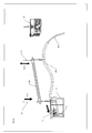
- a connector assembly 52 of a first embodiment of the present invention for use in connecting a power cable 10 to the tidal turbine of Figure 3 has a receiver frame 54 attached to the turbine and having a first component 56 of a wet mate connector attached thereto, and a cable termination head 58 supporting a second component 60 of the wet mate connector and adapted to be located in position in the receiver frame 54 by means of a lift cable 62 attached to a crane (not shown).
- a bend limiter 64 prevents excessive bending of the cable 10 which is connected via cable termination 66 and junction box 68 to the second component 60 of the connector.
- Dampers in the form of retractable pistons 70 are mounted to guides extending from a lower surface 72 of the cable termination head 58, and the lower parts of the pistons 70 are provided with first inclined surfaces 74 for engaging second inclined surfaces 76 on locating members 78 provided on the receiver frame 54.
- coarse alignment is achieved by locating the cable termination head 58 in the receiver frame 54.
- the first inclined surfaces 74 of pistons 70 engage the second inclined surfaces 76 on the receiver frame 54 to bring the first 56 and second 60 components into closer alignment with each other, as shown in Figure 8 .
- an arrangement of a second embodiment of the present invention operates in a similar manner to the first embodiment, but dampers are not provided.
- coarse alignment is achieved by locating the cable termination head in the receiver frame, as in the first embodiment, and finer alignment is then achieved by means of a heavy duty docking probe.
- the automatic latch is pushed aside and finer alignment is then achieved by means of a lateral float in the wet mate connectors and the mounting plate.
Landscapes
- Physics & Mathematics (AREA)
- General Physics & Mathematics (AREA)
- Optics & Photonics (AREA)
- Other Liquid Machine Or Engine Such As Wave Power Use (AREA)
Priority Applications (1)
| Application Number | Priority Date | Filing Date | Title |
|---|---|---|---|
| EP12189353.1A EP2722948A1 (fr) | 2012-10-19 | 2012-10-19 | Appareil de support pour composants interconnectés |
Applications Claiming Priority (1)
| Application Number | Priority Date | Filing Date | Title |
|---|---|---|---|
| EP12189353.1A EP2722948A1 (fr) | 2012-10-19 | 2012-10-19 | Appareil de support pour composants interconnectés |
Publications (1)
| Publication Number | Publication Date |
|---|---|
| EP2722948A1 true EP2722948A1 (fr) | 2014-04-23 |
Family
ID=47263061
Family Applications (1)
| Application Number | Title | Priority Date | Filing Date |
|---|---|---|---|
| EP12189353.1A Ceased EP2722948A1 (fr) | 2012-10-19 | 2012-10-19 | Appareil de support pour composants interconnectés |
Country Status (1)
| Country | Link |
|---|---|
| EP (1) | EP2722948A1 (fr) |
Cited By (2)
| Publication number | Priority date | Publication date | Assignee | Title |
|---|---|---|---|---|
| GB2520523A (en) * | 2013-11-22 | 2015-05-27 | Tidal Generation Ltd | Subsea cable engagement system |
| EP3000716A1 (fr) * | 2014-09-23 | 2016-03-30 | Soil Machine Dynamics Limited | Appareil de positionnement d'un objet sous-marin |
Citations (2)
| Publication number | Priority date | Publication date | Assignee | Title |
|---|---|---|---|---|
| US4171922A (en) * | 1977-03-18 | 1979-10-23 | Seal Participants (Holdings) Limited | Process for positioning and joining ducts of a block |
| GB1594125A (en) * | 1978-05-23 | 1981-07-30 | Ferranti Ltd | Electric connectors |
-
2012
- 2012-10-19 EP EP12189353.1A patent/EP2722948A1/fr not_active Ceased
Patent Citations (2)
| Publication number | Priority date | Publication date | Assignee | Title |
|---|---|---|---|---|
| US4171922A (en) * | 1977-03-18 | 1979-10-23 | Seal Participants (Holdings) Limited | Process for positioning and joining ducts of a block |
| GB1594125A (en) * | 1978-05-23 | 1981-07-30 | Ferranti Ltd | Electric connectors |
Cited By (4)
| Publication number | Priority date | Publication date | Assignee | Title |
|---|---|---|---|---|
| GB2520523A (en) * | 2013-11-22 | 2015-05-27 | Tidal Generation Ltd | Subsea cable engagement system |
| GB2520523B (en) * | 2013-11-22 | 2016-09-21 | Tidal Generation Ltd | Subsea cable engagement system |
| US9929563B2 (en) | 2013-11-22 | 2018-03-27 | Tidal Generation Limited | Subsea cable engagement system |
| EP3000716A1 (fr) * | 2014-09-23 | 2016-03-30 | Soil Machine Dynamics Limited | Appareil de positionnement d'un objet sous-marin |
Similar Documents
| Publication | Publication Date | Title |
|---|---|---|
| US8991501B2 (en) | Separation device | |
| CN104995807B (zh) | 电缆和/或光缆用湿式耦合连接组装件 | |
| US9395021B2 (en) | System and method for interconnecting umbilicals for conveying energy, fluids and/or data in a marine environment | |
| EP2957006B1 (fr) | Procédé pour installer un ensemble de connexion pouvant être accouplé à l'état mouillé pour câbles électriques et/ou optiques | |
| GB2501249A (en) | Power export infrastructure system for a water-based power generation installation | |
| EP2722948A1 (fr) | Appareil de support pour composants interconnectés | |
| US12230910B2 (en) | Single phase coupler | |
| CN105164879B (zh) | 用于可湿式配合连接组件的自动上紧器 | |
| EP3000716A1 (fr) | Appareil de positionnement d'un objet sous-marin | |
| EP3008328B1 (fr) | Équipement de génération d'énergie | |
| CN106165229B (zh) | 水下线缆接合系统 | |
| EP2565367A1 (fr) | Station d'accueil sous-marine | |
| GB2519943A (en) | Apparatus and method | |
| EP4331062B1 (fr) | Dispositif d'accouplement de connecteur | |
| US8960300B2 (en) | Remote subsea connection equipment | |
| CA2949735C (fr) | Ameliorations des connexions sous-marines | |
| WO2015110364A1 (fr) | Châssis de levage de turbine submersible | |
| US12614874B2 (en) | ROV mateable subsea coupler | |
| GB2534227A (en) | Lifting system | |
| US20220219790A1 (en) | Mooring latch for marine structures | |
| GB2463239A (en) | Subsea parking device | |
| AU2013204041A1 (en) | Underwater Power Generator | |
| KR20210045623A (ko) | 수상 도킹방식 무장탑재 시스템 | |
| EP3000715A1 (fr) | Dispositif de verrouillage pour objet sous-marin | |
| GB2444873A (en) | Underwater connector with guide means |
Legal Events
| Date | Code | Title | Description |
|---|---|---|---|
| PUAI | Public reference made under article 153(3) epc to a published international application that has entered the european phase |
Free format text: ORIGINAL CODE: 0009012 |
|
| AK | Designated contracting states |
Kind code of ref document: A1 Designated state(s): AL AT BE BG CH CY CZ DE DK EE ES FI FR GB GR HR HU IE IS IT LI LT LU LV MC MK MT NL NO PL PT RO RS SE SI SK SM TR |
|
| AX | Request for extension of the european patent |
Extension state: BA ME |
|
| STAA | Information on the status of an ep patent application or granted ep patent |
Free format text: STATUS: THE APPLICATION HAS BEEN REFUSED |
|
| 18R | Application refused |
Effective date: 20140512 |