EP2722960B1 - Système de gestion de microréseaux - Google Patents
Système de gestion de microréseaux Download PDFInfo
- Publication number
- EP2722960B1 EP2722960B1 EP11867900.0A EP11867900A EP2722960B1 EP 2722960 B1 EP2722960 B1 EP 2722960B1 EP 11867900 A EP11867900 A EP 11867900A EP 2722960 B1 EP2722960 B1 EP 2722960B1
- Authority
- EP
- European Patent Office
- Prior art keywords
- power supply
- load
- facilities
- output
- supply facilities
- Prior art date
- Legal status (The legal status is an assumption and is not a legal conclusion. Google has not performed a legal analysis and makes no representation as to the accuracy of the status listed.)
- Not-in-force
Links
Images




Classifications
-
- H—ELECTRICITY
- H02—GENERATION; CONVERSION OR DISTRIBUTION OF ELECTRIC POWER
- H02J—ELECTRIC POWER NETWORKS; CIRCUIT ARRANGEMENTS OR SYSTEMS FOR SUPPLYING OR DISTRIBUTING ELECTRIC POWER; SYSTEMS FOR STORING ELECTRIC ENERGY
- H02J3/00—Circuit arrangements for AC mains or AC distribution networks
- H02J3/003—Load forecast, e.g. methods or systems for forecasting future load demand
-
- H—ELECTRICITY
- H02—GENERATION; CONVERSION OR DISTRIBUTION OF ELECTRIC POWER
- H02J—ELECTRIC POWER NETWORKS; CIRCUIT ARRANGEMENTS OR SYSTEMS FOR SUPPLYING OR DISTRIBUTING ELECTRIC POWER; SYSTEMS FOR STORING ELECTRIC ENERGY
- H02J3/00—Circuit arrangements for AC mains or AC distribution networks
-
- H—ELECTRICITY
- H02—GENERATION; CONVERSION OR DISTRIBUTION OF ELECTRIC POWER
- H02J—ELECTRIC POWER NETWORKS; CIRCUIT ARRANGEMENTS OR SYSTEMS FOR SUPPLYING OR DISTRIBUTING ELECTRIC POWER; SYSTEMS FOR STORING ELECTRIC ENERGY
- H02J3/00—Circuit arrangements for AC mains or AC distribution networks
- H02J3/38—Arrangements for feeding a single network from two or more generators or sources in parallel; Arrangements for feeding already energised networks from additional generators or sources in parallel
- H02J3/381—Dispersed generators
-
- H—ELECTRICITY
- H02—GENERATION; CONVERSION OR DISTRIBUTION OF ELECTRIC POWER
- H02J—ELECTRIC POWER NETWORKS; CIRCUIT ARRANGEMENTS OR SYSTEMS FOR SUPPLYING OR DISTRIBUTING ELECTRIC POWER; SYSTEMS FOR STORING ELECTRIC ENERGY
- H02J3/00—Circuit arrangements for AC mains or AC distribution networks
- H02J3/38—Arrangements for feeding a single network from two or more generators or sources in parallel; Arrangements for feeding already energised networks from additional generators or sources in parallel
- H02J3/46—Controlling the sharing of generated power between the generators, sources or networks
-
- H—ELECTRICITY
- H02—GENERATION; CONVERSION OR DISTRIBUTION OF ELECTRIC POWER
- H02J—ELECTRIC POWER NETWORKS; CIRCUIT ARRANGEMENTS OR SYSTEMS FOR SUPPLYING OR DISTRIBUTING ELECTRIC POWER; SYSTEMS FOR STORING ELECTRIC ENERGY
- H02J7/00—Circuit arrangements for charging or discharging batteries or for supplying loads from batteries
- H02J7/34—Parallel operation in networks using both storage and other DC sources, e.g. providing buffering
- H02J7/35—Parallel operation in networks using both storage and other DC sources, e.g. providing buffering with light sensitive cells
-
- H—ELECTRICITY
- H02—GENERATION; CONVERSION OR DISTRIBUTION OF ELECTRIC POWER
- H02J—ELECTRIC POWER NETWORKS; CIRCUIT ARRANGEMENTS OR SYSTEMS FOR SUPPLYING OR DISTRIBUTING ELECTRIC POWER; SYSTEMS FOR STORING ELECTRIC ENERGY
- H02J2101/00—Supply or distribution of decentralised, dispersed or local electric power generation
- H02J2101/10—Dispersed power generation using fossil fuels, e.g. diesel generators
-
- H—ELECTRICITY
- H02—GENERATION; CONVERSION OR DISTRIBUTION OF ELECTRIC POWER
- H02J—ELECTRIC POWER NETWORKS; CIRCUIT ARRANGEMENTS OR SYSTEMS FOR SUPPLYING OR DISTRIBUTING ELECTRIC POWER; SYSTEMS FOR STORING ELECTRIC ENERGY
- H02J2101/00—Supply or distribution of decentralised, dispersed or local electric power generation
- H02J2101/20—Dispersed power generation using renewable energy sources
- H02J2101/22—Solar energy
- H02J2101/24—Photovoltaics
-
- H—ELECTRICITY
- H02—GENERATION; CONVERSION OR DISTRIBUTION OF ELECTRIC POWER
- H02J—ELECTRIC POWER NETWORKS; CIRCUIT ARRANGEMENTS OR SYSTEMS FOR SUPPLYING OR DISTRIBUTING ELECTRIC POWER; SYSTEMS FOR STORING ELECTRIC ENERGY
- H02J2105/00—Networks for supplying or distributing electric power characterised by their spatial reach or by the load
- H02J2105/10—Local stationary networks having a local or delimited stationary reach
-
- Y—GENERAL TAGGING OF NEW TECHNOLOGICAL DEVELOPMENTS; GENERAL TAGGING OF CROSS-SECTIONAL TECHNOLOGIES SPANNING OVER SEVERAL SECTIONS OF THE IPC; TECHNICAL SUBJECTS COVERED BY FORMER USPC CROSS-REFERENCE ART COLLECTIONS [XRACs] AND DIGESTS
- Y02—TECHNOLOGIES OR APPLICATIONS FOR MITIGATION OR ADAPTATION AGAINST CLIMATE CHANGE
- Y02B—CLIMATE CHANGE MITIGATION TECHNOLOGIES RELATED TO BUILDINGS, e.g. HOUSING, HOUSE APPLIANCES OR RELATED END-USER APPLICATIONS
- Y02B70/00—Technologies for an efficient end-user side electric power management and consumption
- Y02B70/30—Systems integrating technologies related to power network operation and communication or information technologies for improving the carbon footprint of the management of residential or tertiary loads, i.e. smart grids as climate change mitigation technology in the buildings sector, including also the last stages of power distribution and the control, monitoring or operating management systems at local level
- Y02B70/3225—Demand response systems, e.g. load shedding, peak shaving
-
- Y—GENERAL TAGGING OF NEW TECHNOLOGICAL DEVELOPMENTS; GENERAL TAGGING OF CROSS-SECTIONAL TECHNOLOGIES SPANNING OVER SEVERAL SECTIONS OF THE IPC; TECHNICAL SUBJECTS COVERED BY FORMER USPC CROSS-REFERENCE ART COLLECTIONS [XRACs] AND DIGESTS
- Y02—TECHNOLOGIES OR APPLICATIONS FOR MITIGATION OR ADAPTATION AGAINST CLIMATE CHANGE
- Y02E—REDUCTION OF GREENHOUSE GAS [GHG] EMISSIONS, RELATED TO ENERGY GENERATION, TRANSMISSION OR DISTRIBUTION
- Y02E10/00—Energy generation through renewable energy sources
- Y02E10/50—Photovoltaic [PV] energy
- Y02E10/56—Power conversion systems, e.g. maximum power point trackers
-
- Y—GENERAL TAGGING OF NEW TECHNOLOGICAL DEVELOPMENTS; GENERAL TAGGING OF CROSS-SECTIONAL TECHNOLOGIES SPANNING OVER SEVERAL SECTIONS OF THE IPC; TECHNICAL SUBJECTS COVERED BY FORMER USPC CROSS-REFERENCE ART COLLECTIONS [XRACs] AND DIGESTS
- Y02—TECHNOLOGIES OR APPLICATIONS FOR MITIGATION OR ADAPTATION AGAINST CLIMATE CHANGE
- Y02E—REDUCTION OF GREENHOUSE GAS [GHG] EMISSIONS, RELATED TO ENERGY GENERATION, TRANSMISSION OR DISTRIBUTION
- Y02E40/00—Technologies for an efficient electrical power generation, transmission or distribution
- Y02E40/70—Smart grids as climate change mitigation technology in the energy generation sector
-
- Y—GENERAL TAGGING OF NEW TECHNOLOGICAL DEVELOPMENTS; GENERAL TAGGING OF CROSS-SECTIONAL TECHNOLOGIES SPANNING OVER SEVERAL SECTIONS OF THE IPC; TECHNICAL SUBJECTS COVERED BY FORMER USPC CROSS-REFERENCE ART COLLECTIONS [XRACs] AND DIGESTS
- Y04—INFORMATION OR COMMUNICATION TECHNOLOGIES HAVING AN IMPACT ON OTHER TECHNOLOGY AREAS
- Y04S—SYSTEMS INTEGRATING TECHNOLOGIES RELATED TO POWER NETWORK OPERATION, COMMUNICATION OR INFORMATION TECHNOLOGIES FOR IMPROVING THE ELECTRICAL POWER GENERATION, TRANSMISSION, DISTRIBUTION, MANAGEMENT OR USAGE, i.e. SMART GRIDS
- Y04S10/00—Systems supporting electrical power generation, transmission or distribution
- Y04S10/12—Monitoring or controlling equipment for energy generation units, e.g. distributed energy generation [DER] or load-side generation
- Y04S10/123—Monitoring or controlling equipment for energy generation units, e.g. distributed energy generation [DER] or load-side generation the energy generation units being or involving renewable energy sources
-
- Y—GENERAL TAGGING OF NEW TECHNOLOGICAL DEVELOPMENTS; GENERAL TAGGING OF CROSS-SECTIONAL TECHNOLOGIES SPANNING OVER SEVERAL SECTIONS OF THE IPC; TECHNICAL SUBJECTS COVERED BY FORMER USPC CROSS-REFERENCE ART COLLECTIONS [XRACs] AND DIGESTS
- Y04—INFORMATION OR COMMUNICATION TECHNOLOGIES HAVING AN IMPACT ON OTHER TECHNOLOGY AREAS
- Y04S—SYSTEMS INTEGRATING TECHNOLOGIES RELATED TO POWER NETWORK OPERATION, COMMUNICATION OR INFORMATION TECHNOLOGIES FOR IMPROVING THE ELECTRICAL POWER GENERATION, TRANSMISSION, DISTRIBUTION, MANAGEMENT OR USAGE, i.e. SMART GRIDS
- Y04S20/00—Management or operation of end-user stationary applications or the last stages of power distribution; Controlling, monitoring or operating thereof
- Y04S20/20—End-user application control systems
- Y04S20/222—Demand response systems, e.g. load shedding, peak shaving
Definitions
- the present invention relates to a control system for microgrid equipment and, more particularly, to a microgrid control system for controlling equipment according to plural equipment characteristics and achieving control that realizes economy, environment-friendliness, and continued operability.
- control is provided such that the total electric output generated is brought into coincidence with the total electric power demand by shortening the periods of outputs of natural energies and the periods of forecasting of load so as to perform accurate forecasts while stopping unnecessary power generators.
- Electric power equipment referred to herein includes solar power generators, wind power generators, diesel generators, gas turbine power generators, brackish water desalination power generators, other power generators, production facilities equipped with power generators employing electric power as motive power (such as refrigerators and push benches), electric vehicles, charging facilities for electric vehicles, and storage batteries for performing charging and discharging with electric power.
- power supply facilities indicate the above-described power generators and secondary batteries such as storage batteries.
- Load facilities indicate the above-described production facilities and charging facilities.
- Patent Literature 1 JP-A-2002-44870
- Söder, L. describes in "Reserve Margin Planning in a Wind-Hydro-Thermal Power System", IEEE transactions on power systems, IEEE Service Center, Piscatawa, NJ, US, vol. 8, no. 2, 1 May 1993 (1993-05-01), pages 564-571 , XP000384307, that large scale introduction of wind power influences the power system operation planning including keeping of spinning reserves, because additional uncertainties are introduced.
- Söder describes a methodology to analyze the operation planning with an emphasis on keeping of reserves. The result from the calculations include instantaneous, fast and slow reserve margins at each hour of the planning period.
- JP 2006 050834 A describes a risk management support system for a power supply enterprise that is supplied to the power supply plant of a power enterprise.
- electricity is generated at in-house facilities for facilities of a contract company, the electric power is procured by purchasing the power procured from the outside source, and it is supplied to a customer.
- JP 2006 304402 A describes a control device for a dispersed energy system.
- An estimating section computes an estimation deviating pattern, wherein the estimated value of the power generation amount of a fuel battery deviates by a fixed value or more and its generation probability.
- a simulating section performs simulation having an operation plan collected from a time when the estimating deviation pattern is judged to occur.
- An evaluation value computing section executes an evaluation value computation by computing the evaluation value in the simulation.
- An optimum operation plan creating section decides an operation plan to provide the best evaluation value.
- patent literature 1 provides control relying on forecasting of output of natural energies and loads.
- a so-called law of great numbers permitting forecasts to hold does not hold and it is impossible to forecast the total amount of load at each instant of time and the amount of natural energy generated. Therefore, when the actual amount of load is greater than forecast, there is the problem that the supply capacity of power generation is insufficient. Furthermore, when the actual amount of load is smaller than forecast, the number of operating power generators is excessive, presenting the problem that the economy is impaired.
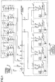
- FIG. 1 is a diagram showing the hardware configuration of a microgrid control system associated with the present embodiment. This configuration is a system built by electrical connection of in-plant systems, power supply facilities, load facilities, and shared power supply facilities within plural plants and by information communication connections. Plants 1-5 receive supply of electric power from a microgrid system 6.
- the microgrid system 6 is interconnected to an external electric power system 7 (e.g., electric power transmission lines of an electric power company; reference voltage is 30 kV).
- the shared power supply facilities 11-17 supply electric power.
- Breakers 41-65 are installed in power feeder lines (electric power lines constituting the microgrid system and in-plant electric power lines). Connection and disconnection between an external system and the microgrid system can be controlled by opening and closing especially 61-64 by means of information communications. Furthermore, when the external system and the microgrid system are disconnected, it is possible to control whether the shared power supply facilities 11-17 are connected with the external system or with the microgrid system.
- Each of the plants 1-5 is equipped with power supply facilities 21-30, load facilities 81-85, and 91-95.
- PCSes Power conditioners
- 111-117 convert the DC power into AC power of a reference voltage of 400 V and output it.
- the power conditioners perform electrical processing for suppression of output in an emergency and for synchronization of frequency (phase control).
- the voltage is transformed from the reference voltage of 400 V to another reference voltage of 30 kV by transformers 131-137. Connection is made to the microgrid system via breakers 121-127 (normally open).
- the system controller 9 receives information from the power supply facilities (the load facilities and power supply facilities) via the information communication network 8, performs computational processing regarding operation of the electric power facilities, and sends control information to the electric power facilities.
- Various types of information (such as control information) are sent and received among the power supply facilities, load facilities, and system controller by employing remote controllers 71-75.
- the remote controller is a wireless LAN.
- Functions can be allotted to the remote controllers and the system controller 9.
- Governors (not shown) are incorporated in the power supply facilities to control mechanical operation based on the control information.
- FIG 2 is a diagram showing the hardware configuration of the system controller 9.
- the system controller 9 is composed of a CPU 201, a main memory 202, an input-output interface 203, a network interface 204, and a storage device 205. These are connected by a bus or the like.
- the network interface 204 is connected with the information communication network 8, and has a function of sending and receiving information to and from the remote controllers 71-75.
- the storage device 205 is composed of a HDD or the like and loaded with programs for realizing the functions of a power supply activating and stopping plan 206, an economical load distribution 207, a facility characteristics identification 208, an operation simulation 209, and remote control information sending and reception 210.
- the CPU 10 realizes the various functions by performing processing for reading the aforementioned programs from the storage device 205 into the main memory 202 and running the programs.
- the aforementioned functions may be implemented in hardware.
- the programs for realizing the functions may be shifted from a storage medium such as a CD-ROM or downloaded from other device via a network.
- FIG. 3 is a diagram showing the hardware configurations of the remote controllers 71-75. These are identical in configuration, and 71 is shown as a representative.
- the remote controller 71 is composed of a CPU 301, a main memory 302, an input-output interface 303, a network interface 304, and a storage device 305. These are connected by a bus or the like.
- the input-output interface 303 has functions of sending and receiving control information to and from the power supply facilities and of sending and receiving information to and from the load facilities.
- the network interface 304 is connected with the information communication network 8, and has a function of sending and receiving information to and from the system controller 9.
- the storage device 305 is made of a HDD or the like and loaded with programs for realizing the functions of system control information sending and reception 306, power supply facility control information sending and reception 307, and load facility information sending and reception 308.
- the CPU 10 realizes the various functions by performing processing for reading the aforementioned programs from the storage device 305 into the main memory 302 and running the programs.
- the foregoing functions may be implemented in hardware.
- the programs for realizing the functions may be shifted from a storage medium such as a CD-ROM or downloaded from other device via a network.
- FIG. 5 is a flowchart illustrating a summary of the processing of the microgrid control system and ancillary processing.
- the power supply activating and stopping plan 206 for drafting a plan of selecting DEG machines to select a number of DEGs of high power generation efficiencies which are necessary to supply electric power to the load is first performed (S501). Then, processing of the economical load distribution 207 for determining economical output distribution from the fuel consumption characteristics of the DEGs determined by the power supply activating and stopping plan 206 is performed (S502). Processing of the facility characteristics identification for sequentially updating the contents of the data from the operation data about the microgrid is performed (S503). Subsequently, simulation processing for effecting various operation simulations and displaying the results on input-output means is performed (S504).
- the system is composed of the blocks of the power supply activating and stopping plan 206, economical load distribution 207, facility characteristics identification 208, and operation simulation 209.
- the blocks have the following functional configurations.
- the blocks correspond to the various programs stored in the storage device 205 described in connection with FIG 2 .
- the block of the power supply activating and stopping plan 206 consists of a demand and solar photovoltaic output forecasting portion 401, a demand and solar photovoltaic output predictive error forecasting portion 402 for forecasting generation of errors of forecasting of the demand made by the load facilities and errors of forecasting of the output from the solar power generators, a probabilistic optimum power supply activation amount determining portion 403 for determining the amount of activation of the DEGs for causing the microgrid to perform an interconnected operation (parallel operation) and the amount of the operation of the solar power generation facilities interconnected to the microgrid (this amount of activation of DEGs is a target value of the total of the rated outputs of the DEGs to be activated) from the forecast values of the demand and solar photovoltaic output and the forecast values of their forecast errors, a DEG machine selecting portion 404, and a solar photovoltaic generation interconnection distributing portion 405.
- DEG machines are selected after determining the total amount of activated DEG power supplies from the reference values about the demand and solar power output and from fringe values calculated from them. Details thereof are hereinafter described.
- the demand and solar photovoltaic output forecasting portion 401 forecasts reference values of the demand and solar photovoltaic output (daily, long-term varying components) from a daily reference value of assumed load (forecasted from the rated electric powers of the load facilities and from data about past results of operations of the load facilities in separate days of the week such as average load factors) and from a daily reference value of solar photovoltaic output (forecasted from theoretical data about the amount of solar incidence, from data about forecasted weathers, and from data about power generation efficiencies).
- time-sequential data that is a reference value of the demand of electric power during a planned period within the microgrid is first forecasted as forecasted demand of electric power from information about actual results of the operation of the load facilities 81-85 and 91-95.
- a time series ⁇ D (t) ⁇ of a reference value (e.g., average value) of the total amount of demand is forecasted by obtaining information about a schedule from a plan of operation of the load facilities (corresponding to a so-called production plan execution system function) and adding up the average values of electric powers actually used in the past of the operated load facilities which are scheduled to be operated.
- the reference value of the electric power generated by each of the solar photovoltaic panels 101-106 during a planned period is forecasted.
- the forecasts are made from the capability value PV ⁇ (i) of the solar panels for converting sunlight into electrical energy (where i the serial number given to each of the solar photovoltaic panels 101-106; information about each PV ⁇ (i) is determined by making an amendment to the reference value of the recording in a facility profile management portion 408 considering variations in characteristics such as air temperature) and from forecasts of the amount of solar radiation.
- the maximum value of the amount of solar radiation on the solar photovoltaic panels is mathematical formula (1).
- the output from the solar photovoltaic panels is forecasted by multiplying the above-described amount of solar radiation (sin (h (t)) by a transmission solar radiation factor C that is a conversion factor for the amount of solar radiation actually reaching the solar photovoltaic panels through clouds or the like. That is, a time series ⁇ PV (t) ⁇ of the solar photovoltaic output is calculated from mathematical formulas 2 and 3.
- the transmission solar radiation factor C is held as a statistical value in calendar days of the year in the facility profile management portion 408. Furthermore, the transmission solar radiation factor C may be corrected by using a value obtained by multiplying either an image derived from an external camera looking at airy clouds or data about the thicknesses of clouds derived using a radar by a given coefficient.
- a time series of (D (t) - PV (t) ⁇ that is a reference value of the amount of electric power that the DEGs must supply is calculated from the ⁇ D (t) ⁇ and ⁇ PV (t) ⁇ computed in this way.
- the planned period is assumed to be 24 hours from the present instant of time.
- the amount of demanded electric power and the amount of electric power produced by solar photovoltaic generation can be forecasted as time series of increments of 30 minutes.
- the present invention is not restricted to this example.
- the planned period may be set in conformity with time constraints on connection and disconnection of a system of power supply facilities such as solar photovoltaic generators (e.g., when a manipulation for connection or disconnection is allowed only once in 48 hours, the planned period is set to 48 hours).
- the demand and solar photovoltaic output predictive error forecasting portion 402 makes forecasts regarding generation of errors concerning the demand, i.e., daily assumed load reference value, the daily reference value of the output produced by solar photovoltaic generation, and errors (mainly, short-term varying components (fringe components) deviating from the demanded amount of electric power that is a forecasted reference value and from long-term varying components of the amount of output produced by solar photovoltaic generation) of each instantaneously demanded amount of electric power and the amount of output produced by solar photovoltaic generation relative to their respective reference values or the total value of both reference values.
- errors mainly, short-term varying components (fringe components) deviating from the demanded amount of electric power that is a forecasted reference value and from long-term varying components of the amount of output produced by solar photovoltaic generation
- statistically generated tendency data which are likely to generate fringe occurrence frequencies and reproducibility of its magnitude are calculated as data associated with forecasting of generation of errors of forecasts.
- the planned period is divided into given periods of consideration (in the aforementioned example, the planned period is taken to be 24 hours from the present instant of time; time zones each of 30 minutes are taken as the periods of consideration).
- period of consideration t one period of consideration starting at time t.
- period of consideration t the period of consideration from time t to time (t + 30 minutes) is denoted as period of consideration t, for the sake of simplicity.
- the system controller has means for directly measuring events of activation or deactivation of the loading facilities
- the system controller records activating and deactivating events, thus realizing this processing.
- the processing may be carried out by regarding a rapid increase in the load curve of the total demanded amount of electric power as an event for activating load facilities and regarding a rapid decrease of the load curve as an event for deactivating load facilities.
- a maximum magnitude ⁇ PVdown (t) ⁇ of decreases of short-term drops (instantaneous drops) of the solar photovoltaic output of variations of photovoltaic outputs from the solar photovoltaic panels 101-106 and the average E_PVdown_count of the number of the generated drops and dispersion ⁇ _PVdown_count are calculated.
- the system controller records and holds data obtained by measuring the solar photovoltaic output. Based on the past data, the above-described values are calculated.
- the difference between the value of mathematical formulas 2 and 3 in which the transmission solar radiation factor C is set to a theoretical maximum value of 1.0 or the like and the forecasted reference value ⁇ PV (t) ⁇ of the aforementioned solar photovoltaic output may be set to ⁇ PVup (t) ⁇ . In this case, execution from the beginning of introduction of the system at which past data are not stored is possible.
- the demand and solar photovoltaic output predictive error forecasting portion 402 may calculate the number of airy clouds, the widths of the clouds, the thicknesses of the clouds, and the speeds at which the clouds are moving, estimate variations of the transmission solar radiation coefficient C, and calculate ⁇ PVdown (t) ⁇ , E_PVdown_count, dispersion ⁇ _PVdown_count, ⁇ PVup (t) ⁇ , E_PVup_count, and dispersion ⁇ _PVup_count from current data obtained from an external camera observing airy clouds or a radar or from past data about these.
- fringes may be forecasted nonstatistically from a schedule of control of the operation of electric power facilities or by direct observation of daily climatic phenomena.
- the remote controllers 71-75 may accept reservations for activation of load facilities. Consequently, the system controller 9 can more accurately forecast short-term variations ⁇ Dup (t) ⁇ of the amount of electric power demanded.
- the probabilistic optimum power supply activation amount determining portion 403 performs the following processing to determine a target value of the total of the rated outputs of activated DEGs and the amount of interconnection of solar photovoltaic panels interconnected with the microgrid.
- the amount of electrical output Pdeg (t) [kW] that each DEG should bear in each period of consideration t is calculated as given by mathematical formula 4, based on ⁇ D (t) ⁇ and ⁇ PV (t) ⁇ which is information about the electric power demanded in each period of consideration t and the solar photovoltaic power which has been found in the block 401, on a maximum magnitude ⁇ Dup (t) ⁇ of the incremental amount of electric power for short-term demand, and on a maximum magnitude ⁇ PDdown (t) ⁇ of the short-term decremental amount of the solar photovoltaic output.
- P deg t D t ⁇ PV t + ⁇ PVdown t + ⁇ Dup t ⁇ Mup_E_ ⁇
- a spare amount of output (instantaneous reserve capability) of the DEG is secured.
- the spare amount of output is secured by multiplying [ ⁇ PVdown (t) + ⁇ Dup (t)] by a safety factor (Mup_E_ ⁇ ).
- this safety factor is set to a value of 1.0 or higher.
- Mup_E_ ⁇ is set to a large value.
- a comparison table between ⁇ _PVdown_count and Mup_E_ ⁇ may be created. Furthermore, where ⁇ _Dup_count is large, Mup_E_ ⁇ may be set to a large value, and a comparison table for them may be built. Where processing in which a comparison table is previously created in this way and Pdeg (t) is calculated is performed, information about Mup_E_ ⁇ may be extracted from this comparison table and computational processing may be performed. According to this method, when the comparison table is created, the lower limit of Mup_E_ ⁇ for securing a reserve amount of output necessary to avoid voltage drops of the microgrid system and frequency decreases due to a lack of the DEG output can be previously optimized by a test environment or a computer simulation.
- ⁇ _ ⁇ (t) the dispersion value of the set ⁇ Dup_i ⁇ of Dup_i of the sizes of fringes due to either activation of load facilities during period t or a decrease in the solar photovoltaic output is denoted as ⁇ _ ⁇ (t)) of sizes of fringes produced in periods
- Mup_E_ ⁇ may be increased.
- the amount by which the solar photovoltaic panels are interconnected to the microgrid is determined (determination of the set J of the panel numbers interconnected with the microgrid) as follows.
- Mdown_E_ ⁇ is set to a larger value (e.g., 1.2).
- a comparison table among ⁇ _ ⁇ down (t), the count, and Mdown_E_ ⁇ may be created.
- information about Mdown_E_ ⁇ may be extracted from the comparison table and computational processing may be carried out.
- the comparison table is created, the value of Mdown_E_ ⁇ for securing an amount of output which can be reduced and which is necessary to avoid faults disturbing the system voltage can be previously optimized by a test environment or a computer simulation.
- the set J of panel numbers of the solar photovoltaic panels interconnected to the microgrid is reduced until mathematical formula 5 is satisfied (obviously, if the solar photovoltaic panels are installed under the same conditions, the number of the solar photovoltaic panels is in proportion to ⁇ PVup (t)).
- the DEG machine selecting portion 404 selects DEGs which satisfy the DEG activation amount determined as described above with a priority on DEGs having good fuel efficiency.
- selection of DEG machines continues in preparation for a fault of one DEG (N - 1 accident) until an output equivalent to Pdeg (t) appears if that of selected DEGs which has the greatest rated output is stopped by an accident.
- DEG fuel efficiency refers to the fuel consumption in a central load region. That is, R of mathematical formula 6 is found as a rough number of a load factor steadily applied to DEGs.
- Calculations are performed based on the fuel consumptions (liters/hour) of the DEGs which are run at a load factor of this R (output at a ratio of R of the rated output, kW, intrinsic to each DEG) and on the fuel consumption characteristic formulas intrinsic to the DEGs set forth in the facility profiles 408.
- DEG machines are selected in turn first from the DEG machines having smaller calculated values (preferable DEG machines having small fuel consumptions). That is, DEG machines are selected in turn until the total of the rated outputs of the selected DEG machines exceeds the above-described Pdeg (t).
- DEG machines may be selected in turn first from the DEG having the best fuel consumption at the rated output of DEG This is an effective method in a case where fuel consumption characteristics at partially loaded output of DEGs are not known.
- processing from the block 401 may be again performed in such a way that the number of solar photovoltaic panels interconnected to the microgrid is reduced (J is reduced) so as to increase the value of R.
- a given threshold value e.g., 0.3 or less
- processing from the block 401 may be again performed in such a way that the number of solar photovoltaic panels interconnected to the microgrid is reduced (J is reduced) so as to increase the value of R.
- a given threshold value may be set for R at each magnitude of Pdeg (t).
- Pdeg (t) is less than 1000 kW
- the threshold value is set to 0.3.
- Pdeg (t) is equal to or higher than 1000 kW
- the threshold value is set to 0.4.
- a correction may be made such that a DEG once activated is continually activated with a priority even in the next period of consideration.
- the number of stops of activation of DEGs is reduced. This produces the effect that fuel needed for warm-up of the DEGs is reduced.
- the solar photovoltaic generation interconnection distributing portion 405 determines intervals in which the interconnected breakers for solar photovoltaic generation are opened according to the set J of the numbers of the solar photovoltaic panels interconnected to the microgrid such that the required amount of interconnections is achieved. Thus, even if DEG outputs are made zero, increases of AC frequency of the microgrid or abnormal voltage increase which would be caused by the fact that supply of electric power exceeds can be suppressed.
- the block of the economical load distribution 207 consists of DEG economical load distributing portions 406 which are operated parallel in an interconnected relation to the microgrid system and which determine economical output burden shares from the respective fuel consumption characteristics of the DEGs determined by the power supply activating and stopping plan 206.
- economical output burden shares of DEGs are determined as economical load burden shares by an equal increment fuel consumption method (equal ⁇ method).
- the lambda value is given by mathematical formula 7.
- ⁇ _i dFc i / dW i , where i is a number given to the DEG machine, Fc (i) is the fuel consumption characteristic ((liters/hour)/kW) of the i-th DEG machine, and W (i) is the output from the i-th DEG machine.
- a set I of DEG machine numbers in operation satisfies mathematical formula 8.
- ⁇ _i ⁇ _j with respect to arbitrary i , j ⁇ I
- the supply and demand balance of the system in the planned period can be maintained by making the total of the outputs from the DEGs satisfy mathematical formula 9.
- P deg t ⁇ i ⁇ I W i
- DEGs satisfying the above-described mathematical formulas 8 and 9 are run.
- Set values of frequency droop for the DEGs, respectively, are calculated.
- the calculated values are transmitted to the governors of the DEGs via the remote controllers 71-75.
- the governors of the DEGs update the set values of frequency droop to the received values.
- the block of the facility characteristics identification 208 offers facility profile information necessary for the blocks of power supply activating and stopping plan 206, economical load distribution 207, and operation simulation 209.
- the facility profiles are information about the output characteristics of the power supply facilities, output variability, responsiveness, fuel consumption characteristics, fuel increment characteristics, fringe characteristics (frequency at which operation of the load facilities is stopped, rated input, frequency at which incident solar radiation associated with solar photovoltaic generation varies, magnitude), time range characteristics of environment-friendly operation, load characteristics of environment-friendly operation, and so on.
- the block of the facility characteristics identification 208 consists of the facility profile management portion 408 for holding and outputting facility profile data and a facility profile learning portion 409 for learning profile information about facilities on an on-line basis from on-line formation including information about operation of the electric power facilities interconnected to the microgrid, the frequency of the microgrid, and information about the voltage and electric power of the electric power facilities.
- the data contents are serially updated from data about the operation of the microgrid by a learning technique such as system identification approach, error back propagation method, or delta rule.
- the block of the operation simulation 209 consists of a stability simulation portion 410 for making prior assessments of the transient stability and steady-state stability of the configurations of power supplies that are parallel to the microgrid determined by the block of the power supply activating and stopping planning portion 206, an environment assessment simulation portion 412 for making a prior assessment of the state of exhaust gas from the DEGs, and an operation check and indicating portion 411 for displaying the results of the stability simulations and the results of the environment assessment simulation on input-output means and obtaining a confirmatory input from a human operator.
- the probabilistic optimum power supply activation amount planning portion 403 again modifies the determination such that the amount by which DEGs are activated is increased or the amount of interconnection of solar photovoltaic generation is reduced.
- the probabilistic optimum power supply activation amount planning portion 403 again modifies either the amount by which the DEGs are activated or the determined amount of interconnection of the solar photovoltaic generation.
- the probabilistic optimum power supply activation amount planning portion 403 makes a modification such that the amount of interconnection of the amount of solar photovoltaic generation is reduced. This increases the load factor of the DEGs and raises the fuel combustion temperature, thus reducing exhaust gas black smoke. Furthermore, as an example, if an instruction is given to mitigate rapid variations of the DEG output, the probabilistic optimum power supply activation amount planning portion 403 again determines such that the amount of interconnection of solar photovoltaic generation causing variations is modified. In addition, for example, if an instruction is given to mitigate the danger of instantaneously overloaded operation of DEGs, the probabilistic optimum power supply activation amount planning portion 403 again determines such that the number of interconnected DEGs is increased.
- FIG. 6 shows facility profiles while taking the DEG 21 as an example.
- X coordinate > 187635. GmlPosition. Y coordinate 772863), rated output (1000 kVA) of the equipment that indicates electrical and mechanical characteristics, maximum output (1100 kVA), minimum output 100 kVA, a fuel function (Fuel consumption function, F (x) 0.0001 x*x+0.01x + 10) indicating a fuel amount [liters/hour] consumed when the output is x [kW], a fuel increment ⁇ (0.0001*x + 0.01) indicating a fuel amount [liters/hour] necessary for an output increment of x [kW], characteristics of constraints on environment-friendly operation associated with equipment operation (such as the characteristics of the output at the lower limit of long-term lightly loaded operation (400 kVA) and the characteristics of limit time (time for which long-term lightly loaded operation is possible; 120 min) in which the exhaust gas components start to deteriorate as a result of the long-term lightly loaded operation), especially dynamic electrical characteristics (such as information associated with responsiveness when the output varies (e.g.,
- the above-described dynamic electrical characteristics can be represented in terms of a transfer function.
- they may be set forth using a polynomial model such as ARMA or using data obtained by plotting response characteristics.
- FIG 7 is a diagram showing the hardware configuration of a power supply facility 21.
- the power supply facility is a diesel generator (DEG).
- the power supply equipment 21 comprises a diesel engine 701, a governor 702 that is an engine control portion, a power generator 703, and an automatic voltage regulator AVR (automatic voltage regulator) 704, and are connected with the remote controller 71. Under instructions from the remote controller 71, the governor 702 adjusts the amount of fuel ejected into the engine 701 to vary the output torque of the engine, thus controlling the rotational speed of the engine (frequency of the power generator).
- DEG diesel generator
- AVR automatic voltage regulator
- the remote controller 71 gives instructions on set values of frequency droop for the governors of the power generation facilities.
- the governor 702 provides droop control using the frequency droop.
- FIG 8 is a diagram illustrating that DEG output allocations are adjusted by varying the settings of the DEG frequency droop.
- the frequency droop is set such that a rated output is provided at a rated frequency.
- the load is gradually reduced.
- the difference between a frequency occurring when no load is applied and the rated frequency is expressed in terms of percentage.
- 801 A is a frequency/output characteristic line at a 5% frequency droop of the DEG 21 having a rated output of 1000 kW.
- 802A is a frequency/output characteristic line at a 5% frequency droop of the DEG 22 having a rated output of 500 kW.
- the microgrid control system can arbitrarily control each DEG output.
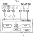
- FIG 9 is a diagram illustrating the relation between the software configuration and facility I/Os of the microgrid control system.
- the power supply activating and stopping plan 206, economical load distribution 207, and facility characteristics identification 208 which are functional processings of the microgrid control select DEG machines (selected DEGs are run in parallel and synchronously) according to the information about the facility profiles indicative of the DEG characteristics and the facility information indicative of the characteristics of the load facilities and send and receive the values of frequency droop giving conditions under which the selected DEGs operate using communication software between the system controller and the remote controller.
- the solar power generators With respect to interconnection of the solar power generators with the microgrid, it is possible to control how many solar power generators are interconnected by an instruction given to breakers via an I/O.
- FIG 10 is a diagram illustrating the advantageous effects of the present embodiment.
- excessive DEG activation can be suppressed by appropriately forecasting predictive errors in variations in solar photovoltaic output and load variations. Consequently, the fuel amount per unit time required by each DEG can be reduced.
- the present embodiment makes it possible to prevent deterioration of DEG exhaust gas components due to long-term, lightly loaded operation and generation of blackout due to shortage of the DEG output.
- FIG 11 is a diagram showing variations in the DEG output allotments when the present embodiment is implemented.
- first and second DEG machines are in operation and the output is distributed between the two DEG machines.
- the first machine has a rated output of 1000 kW.
- the second machine has a rated output of 750 kW. (Here, when the first machine is higher in load factor than the second machine, a better fuel consumption is obtained).
- the outputs of the first and second machines are allotted according to ⁇ shown in mathematical formula 7. Under high load conditions (total output of 1750 kW), both machines are operated in their rated output. In lightly loaded regions, the first machine provides a higher output than the second machine.
Landscapes
- Engineering & Computer Science (AREA)
- Power Engineering (AREA)
- Supply And Distribution Of Alternating Current (AREA)
Claims (9)
- - Système de commande de micro-réseau pour commander des opérations d'une pluralité d'équipements d'énergie électrique, comprenant :une partie de planification d'activation et d'arrêt de machine d'alimentation électrique (206) ; etune partie de distribution de charge économique (207) pour déterminer des valeurs d'instruction associées à des allocations d'une charge aux équipements d'énergie électrique ;dans lequel ladite partie de planification d'activation et d'arrêt de machine d'alimentation électrique (206) possède :une fonction de prévision de charge de sortie pour prévoir des quantités de sortie des équipements d'énergie électrique et des quantités de charge sur les équipements de charge,une fonction de prévision d'erreurs de prédiction de charge de sortie pour prévoir des.erreurs des sorties prévues et des quantités de charge prévues,une fonction de détermination de quantité d'activation d'alimentation électrique (403) pour déterminer une quantité totale de sortie d'équipements d'énergie électrique à activer, sur la base de résultats des prédictions réalisées par la fonction de prévision de charge de sortie et la fonction de prévision d'erreurs de prédiction de charge de sortie, etune fonction de sélection d'équipements d'énergie électrique pour sélectionner des équipements d'énergie électrique à activer, sur la base de la quantité totale déterminée de sortie et d'informations de caractéristique concernant les équipements d'énergie électrique,caractérisé par le fait que :des panneaux solaires (101-106) et des groupes électrogènes diesel (21) sont prévus en tant qu'équipements d'énergie électrique,dans lequel ladite fonction de sélection d'alimentation électrique calcule des facteurs de charge qui sont des rapports de charge des groupes électrogènes diesel (21) et limite la sortie en provenance des panneaux solaires (101-106) des équipements d'énergie électrique par réduction du nombre des panneaux solaires (101-106) qui se lient au micro-réseau si les facteurs de charge sont en dessous d'une valeur de seuil donnée.
- - Système de commande de micro-réseau selon la revendication 1, dans lequel lesdites informations de caractéristique concernant les équipements d'énergie électrique sont des informations concernant des caractéristiques de consommation de carburant des équipements d'énergie électrique, et dans lequel ladite fonction de sélection d'équipements d'énergie électrique sélectionne les équipements d'énergie électrique à activer de telle sorte qu'ils sont sélectionnés tour à tour en partant de l'équipement d'énergie électrique ayant des caractéristiques de consommation de carburant faible sur la base desdites informations de caractéristique de consommation de carburant.
- - Système de commande de micro-réseau selon la revendication 2, dans lequel lesdites informations de caractéristique de consommation de carburant sont une caractéristique de consommation de carburant dans une région de charge autour de laquelle lesdits équipements d'énergie électrique fonctionnent.
- - Système de commande de micro-réseau selon la revendication 1, dans lequel ladite fonction de sélection d'équipements d'énergie électrique sélectionne des équipements d'énergie électrique avec une priorité sur des équipements d'énergie électrique actuellement en fonctionnement.
- - Système de commande de micro-réseau selon l'une quelconque des revendications 1 à 4, comprenant en outre une partie d'identification de caractéristique d'équipements (208) pour un apprentissage d'un type quelconque de caractéristique de variabilité, réactivité, consommation de carburant, quantité croissante de consommation de carburant, caractéristiques de charge environnementale, et caractéristiques de. plage temporelle de fonctionnement écologique concernant les sorties des équipements d'énergie électrique ou des charges sur les équipements de charge.
- - Procédé de commande de micro-réseau pour commander des opérations d'une pluralité d'équipements d'énergie électrique, comprenant les étapes consistant à :prévoir des quantités de sortie des équipements d'énergie électrique et des quantités de charges sur des équipements de charge ;prévoir des erreurs des quantités prévues de sorties et des quantités prévues de charges ;déterminer une quantité totale de sortie d'équipements d'énergie électrique à activer, sur la base des résultats des deux prévisions ;sélectionner des équipements d'énergie électrique à activer, sur la base de la quantité totale déterminée de sortie et d'informations de caractéristique concernant les équipements d'énergie électrique ; etdéterminer des valeurs d'instruction associées à des allocation d'une charge aux équipements d'énergie électrique,caractérisé par le fait que :des panneaux solaires (101-106) et des groupes électrogènes diesel (21) sont prévus en tant qu'équipements d'énergie électrique,dans lequel ladite étape de sélection d'équipements d'énergie électrique à activer calcule des facteurs de charge qui sont des rapports de charge des groupes électrogènes diesel (21) et limite la sortie en provenance des panneaux solaires (101-106) des équipements d'énergie électrique par réduction du nombre des panneaux solaires (101-106) qui se lient au micro-réseau si les facteurs de charge sont en dessous d'une valeur de seuil donnée.
- - Procédé de commande de micro-réseau selon la revendication 6, dans lequel lesdites informations de caractéristique concernant les équipements d'énergie électrique sont des informations concernant une caractéristique de consommation de carburant des équipements d'énergie électrique, et dans lequel l'étape de sélection d'équipements d'énergie électrique à activer sélectionne des équipements d'énergie électrique de telle sorte qu'ils sont sélectionnés tour à tour en partant de l'équipement d'énergie électrique ayant des caractéristiques de consommation de carburant faible sur la base desdites informations de caractéristique de consommation de carburant.
- - Procédé de commande de micro-réseau selon la revendication 7, dans lequel lesdites informations caractéristique de consommation de carburant sont une caractéristique de consommation de carburant dans une région de charge autour de laquelle lesdits équipements d'énergie électrique fonctionnent.
- - Procédé de commande de micro-réseau selon la revendication 6, dans lequel l'étape de sélection desdits équipements d'énergie électrique à activer sélectionne des équipements d'énergie électrique avec une priorité sur des équipements d'énergie électrique actuellement en fonctionnement.
Applications Claiming Priority (1)
| Application Number | Priority Date | Filing Date | Title |
|---|---|---|---|
| PCT/JP2011/003461 WO2012172616A1 (fr) | 2011-06-17 | 2011-06-17 | Système de gestion de microréseaux |
Publications (3)
| Publication Number | Publication Date |
|---|---|
| EP2722960A1 EP2722960A1 (fr) | 2014-04-23 |
| EP2722960A4 EP2722960A4 (fr) | 2015-03-11 |
| EP2722960B1 true EP2722960B1 (fr) | 2016-08-17 |
Family
ID=47356644
Family Applications (1)
| Application Number | Title | Priority Date | Filing Date |
|---|---|---|---|
| EP11867900.0A Not-in-force EP2722960B1 (fr) | 2011-06-17 | 2011-06-17 | Système de gestion de microréseaux |
Country Status (4)
| Country | Link |
|---|---|
| US (1) | US9742189B2 (fr) |
| EP (1) | EP2722960B1 (fr) |
| JP (1) | JP5789662B2 (fr) |
| WO (1) | WO2012172616A1 (fr) |
Families Citing this family (42)
| Publication number | Priority date | Publication date | Assignee | Title |
|---|---|---|---|---|
| KR101259728B1 (ko) * | 2011-12-14 | 2013-05-07 | 제주대학교 산학협력단 | 마이크로그리드 운전 제어 시스템 및 방법 |
| US20150073737A1 (en) * | 2012-04-20 | 2015-03-12 | Tatsuki Inuzuka | Power monitoring apparatus and power monitoring method |
| DE102013103894B4 (de) * | 2013-04-17 | 2017-07-13 | Sma Solar Technology Ag | Verfahren und Vorrichtung zum Betrieb eines neben Brennkraftgeneratoren an ein begrenztes Stromnetz angeschlossenen Photovoltaikkraftwerks |
| CN103412526B (zh) * | 2013-07-12 | 2016-03-16 | 国家电网公司 | 一种供热机组在线负荷的调度方法与系统 |
| US8963353B1 (en) * | 2013-09-19 | 2015-02-24 | General Electric Company | System and method to minimize grid spinning reserve losses by pre-emptively sequencing power generation equipment to offset wind generation capacity based on geospatial regional wind conditions |
| US20150333491A1 (en) * | 2014-05-13 | 2015-11-19 | Paul Cruz | Alternative energy bus bar by pass breaker |
| US9728972B2 (en) | 2014-08-20 | 2017-08-08 | Qfe 002 Llc | Alternative energy bus bar by pass breaker, methods of use and installation |
| US20170214273A1 (en) * | 2014-08-04 | 2017-07-27 | Nec Corporation | Distributed power supply system, station control device, control method, and storage medium in which program is stored |
| US11070058B2 (en) * | 2014-10-26 | 2021-07-20 | Green Power Labs Inc. | Forecasting net load in a distributed utility grid |
| JP6623514B2 (ja) * | 2014-11-10 | 2019-12-25 | 東京電力ホールディングス株式会社 | 需給制御装置、需給制御方法及び電力供給システム |
| SG10201502972VA (en) * | 2015-04-15 | 2016-11-29 | Sun Electric Pte Ltd | Method and system for operating a plurality of photovoltaic (pv) generating facilities connected to an electrical power grid network |
| JP6150012B2 (ja) * | 2015-05-27 | 2017-06-21 | 日本電気株式会社 | 発電制御装置、制御装置、制御方法及びプログラム |
| US9683503B2 (en) * | 2015-08-17 | 2017-06-20 | Caterpillar Inc. | Managing load sharing among multiple engines |
| WO2017029756A1 (fr) * | 2015-08-20 | 2017-02-23 | シャープ株式会社 | Système d'alimentation électrique, dispositif de commande de sortie, procédé de commande de sortie, et support d'enregistrement |
| WO2017037889A1 (fr) * | 2015-09-02 | 2017-03-09 | シャープ株式会社 | Système d'alimentation électrique, dispositif de commande de sortie, procédé de commande de sortie, et support d'enregistrement |
| KR101724893B1 (ko) * | 2015-09-08 | 2017-04-07 | 한국전력공사 | 독립형 마이크로그리드 자율제어 시스템 및 방법 |
| JP6600516B2 (ja) * | 2015-09-14 | 2019-10-30 | 株式会社東芝 | アグリゲーション管理装置及び方法 |
| WO2017089402A1 (fr) * | 2015-11-26 | 2017-06-01 | Abb Schweiz Ag | Système d'énergie hybride comprenant des groupes électrogènes et des ressources d'énergie renouvelables, et procédé de commande |
| US10061283B2 (en) | 2015-12-07 | 2018-08-28 | Opus One Solutions Energy Corp. | Systems and methods for integrated microgrid management system in electric power systems |
| ES2773478T3 (es) * | 2016-03-01 | 2020-07-13 | Siemens Ag | Procedimiento y sistema para operar una red de suministro de energía autónoma |
| WO2017203610A1 (fr) * | 2016-05-24 | 2017-11-30 | 三菱電機株式会社 | Dispositif d'estimation de quantité d'énergie électrique produite, système de distribution d'énergie électrique, et procédé d'estimation de quantité d'énergie électrique produite |
| US20170371306A1 (en) * | 2016-06-27 | 2017-12-28 | Ecole Polytechnique Federale De Lausanne (Epfl) | System and Method for Dispatching an Operation of a Distribution Feeder with Heterogeneous Prosumers |
| US10651656B2 (en) | 2016-09-14 | 2020-05-12 | Texas Tech University System | UDE-based robust droop control for parallel inverter operation |
| JP6351796B1 (ja) * | 2017-06-12 | 2018-07-04 | ジャパンマリンユナイテッド株式会社 | 電力供給システム及び電力供給方法 |
| EP3487027B1 (fr) * | 2017-11-21 | 2022-04-27 | Schneider Electric Industries SAS | Procédé de commande d'un micro-réseau |
| DE102018001763A1 (de) * | 2018-03-06 | 2019-09-12 | Senvion Gmbh | Verfahren und System zum Warten einer Windenergieanlage aus einer Gruppe von Windenergieanlagen |
| US10878450B1 (en) * | 2018-04-01 | 2020-12-29 | Facebook, Inc. | Pacing content campaigns by adjusting probability of bidding |
| FR3095067A1 (fr) * | 2019-04-11 | 2020-10-16 | Total Solar | Procédé d'évaluation de la production d’énergie photovoltaïque et unité d’évaluation et de gestion mettant en œuvre le procédé |
| CN109995091B (zh) * | 2019-04-26 | 2022-11-29 | 太原理工大学 | 一种考虑预测误差的交直流混合微电网经济调度方法 |
| CA3079882C (fr) * | 2019-05-01 | 2026-03-17 | Battelle Memorial Institute | Surveillance et commande de l`etat d`appareils electriques a gestion de frequences a partir d'un historique de frequences |
| EP4005050B1 (fr) | 2019-07-29 | 2024-11-13 | Enphase Energy, Inc. | Procédé et appareil d'entrelacement automatique de charges cyclées dans un micro-réseau |
| CN111339689B (zh) * | 2020-03-30 | 2023-02-07 | 广东工业大学 | 建筑综合能源调度方法、系统、存储介质及计算机设备 |
| CN111884258B (zh) * | 2020-07-31 | 2023-08-01 | 三峡大学 | 考虑负荷重要等级的多微网被动并离网平滑切换方法 |
| CN112531699B (zh) * | 2020-12-04 | 2023-08-18 | 广东电网有限责任公司电力调度控制中心 | 一种微电网自治能管系统能量调度方法和系统 |
| US11962156B2 (en) | 2021-08-19 | 2024-04-16 | Caterpillar Inc. | Systems and methods for constrained optimization of a hybrid power system that accounts for asset maintenance and degradation |
| US11936184B2 (en) * | 2021-08-19 | 2024-03-19 | Caterpillar Inc. | Systems and methods for operating hybrid power system by combining prospective and real-time optimizations |
| JP7767990B2 (ja) * | 2022-03-07 | 2025-11-12 | 中国電力株式会社 | 太陽光発電量予測装置、太陽光発電量予測装置の制御方法及びプログラム |
| JP7767989B2 (ja) * | 2022-03-07 | 2025-11-12 | 中国電力株式会社 | 太陽光発電量予測装置、太陽光発電量予測装置の制御方法及びプログラム |
| US12512697B2 (en) * | 2022-03-11 | 2025-12-30 | Universidade Federal De Minas Gerais | Control process for low voltage microgrids with distributed communication |
| RO137478A3 (ro) * | 2022-12-08 | 2024-06-28 | Tokyo Market S.R.L. | Sistem inteligent pentru monitorizarea şi capitalizarea energiei verzi produse de panourile fotovoltaice |
| KR102842080B1 (ko) * | 2023-05-17 | 2025-08-08 | (주)누리플렉스 | 공장에너지에 기반한 마이크로그리드 에너지 수급 밸런싱 시스템 및 그 방법 |
| JP2025147568A (ja) * | 2024-03-25 | 2025-10-07 | 株式会社日立製作所 | 制御設計支援方法、および、制御設計支援装置 |
Family Cites Families (23)
| Publication number | Priority date | Publication date | Assignee | Title |
|---|---|---|---|---|
| JP3782924B2 (ja) | 2000-07-27 | 2006-06-07 | 日本電信電話株式会社 | 分散型エネルギーコミュニティーシステムとその制御方法 |
| JP3780838B2 (ja) * | 2000-09-26 | 2006-05-31 | 株式会社日立製作所 | グリーン電力供給システム及びグリーン電力供給方法 |
| GB0207396D0 (en) * | 2002-03-28 | 2002-05-08 | Bg Intellectual Pty Ltd | A power distribution/generation system |
| US7454270B2 (en) * | 2003-05-13 | 2008-11-18 | Siemens Power Transmission & Distribution, Inc. | Dynamic economic dispatch for the management of a power distribution system |
| WO2005015366A2 (fr) * | 2003-08-08 | 2005-02-17 | Electric Power Group, Llc | Systeme de gestion et de surveillance de resultats en temps reel |
| JP4154373B2 (ja) | 2004-08-06 | 2008-09-24 | 株式会社日立製作所 | 電力供給事業リスク管理支援システム |
| US9771834B2 (en) * | 2004-10-20 | 2017-09-26 | Emerson Process Management Power & Water Solutions, Inc. | Method and apparatus for providing load dispatch and pollution control optimization |
| JP4245583B2 (ja) | 2005-04-15 | 2009-03-25 | 日本電信電話株式会社 | 分散型エネルギーシステムの制御装置、制御方法、プログラム、および記録媒体 |
| JP4527092B2 (ja) * | 2006-08-23 | 2010-08-18 | 三菱電機株式会社 | 系統安定化装置 |
| CN101154815B (zh) * | 2006-09-29 | 2012-08-29 | 霍尼韦尔(中国)高科技有限公司 | 动态经济负荷分配 |
| JP4864803B2 (ja) * | 2007-04-23 | 2012-02-01 | 株式会社東芝 | 電力需給制御装置およびその方法 |
| US7952306B2 (en) * | 2007-06-01 | 2011-05-31 | Progress Rail Services Corp | Power system with multiple generator units |
| US7991512B2 (en) * | 2007-08-28 | 2011-08-02 | General Electric Company | Hybrid robust predictive optimization method of power system dispatch |
| JP4412413B1 (ja) * | 2008-07-31 | 2010-02-10 | パナソニック電工株式会社 | 配電システム |
| US8706650B2 (en) * | 2009-01-14 | 2014-04-22 | Integral Analytics, Inc. | Optimization of microgrid energy use and distribution |
| JP5350942B2 (ja) | 2009-08-25 | 2013-11-27 | 株式会社東芝 | 電力系統の需給制御装置、需給制御プログラム及びその記録媒体 |
| JP5402566B2 (ja) * | 2009-11-25 | 2014-01-29 | 富士電機株式会社 | マイクログリッドの需給制御装置およびマイクログリッドの需給制御方法 |
| US9093840B2 (en) * | 2010-07-02 | 2015-07-28 | Alstom Technology Ltd. | System tools for integrating individual load forecasts into a composite load forecast to present a comprehensive synchronized and harmonized load forecast |
| US8972070B2 (en) * | 2010-07-02 | 2015-03-03 | Alstom Grid Inc. | Multi-interval dispatch system tools for enabling dispatchers in power grid control centers to manage changes |
| US8566266B2 (en) * | 2010-08-27 | 2013-10-22 | Mitsubishi Electric Research Laboratories, Inc. | Method for scheduling the operation of power generators using factored Markov decision process |
| JP5101675B2 (ja) * | 2010-09-09 | 2012-12-19 | 株式会社東芝 | 需給バランス制御装置 |
| US8831788B2 (en) * | 2011-04-20 | 2014-09-09 | General Electric Company | Systems, methods, and apparatus for maintaining stable conditions within a power grid |
| US8996185B2 (en) * | 2011-06-03 | 2015-03-31 | Mitsubishi Electric Research Laboratories, Inc. | Method for scheduling power generators based on optimal configurations and approximate dynamic programming |
-
2011
- 2011-06-17 EP EP11867900.0A patent/EP2722960B1/fr not_active Not-in-force
- 2011-06-17 US US14/126,730 patent/US9742189B2/en not_active Expired - Fee Related
- 2011-06-17 JP JP2013520329A patent/JP5789662B2/ja not_active Expired - Fee Related
- 2011-06-17 WO PCT/JP2011/003461 patent/WO2012172616A1/fr not_active Ceased
Also Published As
| Publication number | Publication date |
|---|---|
| EP2722960A1 (fr) | 2014-04-23 |
| EP2722960A4 (fr) | 2015-03-11 |
| WO2012172616A1 (fr) | 2012-12-20 |
| US9742189B2 (en) | 2017-08-22 |
| JPWO2012172616A1 (ja) | 2015-02-23 |
| US20140252855A1 (en) | 2014-09-11 |
| JP5789662B2 (ja) | 2015-10-07 |
Similar Documents
| Publication | Publication Date | Title |
|---|---|---|
| EP2722960B1 (fr) | Système de gestion de microréseaux | |
| US11710965B2 (en) | Method for implementing power delivery transaction for potential electrical output of integrated renewable energy source and energy storage system facility | |
| Aboshady et al. | Reactive power control of PV inverters in active distribution grids with high PV penetration | |
| US11916383B2 (en) | Implementing power delivery transaction for potential electrical output of integrated renewable energy source and energy storage system facility | |
| EP3931934B1 (fr) | Systèmes et procédés utilisant une ressource de génération électrique renouvelable surchargée à courant alternatif et dispositif de stockage de charge | |
| AU2021218240B2 (en) | Method for determining and managing potential electrical output of integrated renewable energy source and energy storage system facility | |
| Wang et al. | Value stacking of a customer-sited BESS for distribution grid support: A utility case | |
| AU2021107535A4 (en) | Method for implementing power delivery transaction for potential electrical output of integrated renewable energy source and energy storage system facility | |
| US20250125630A1 (en) | Systems and methods for microgrid asset dispatch | |
| Holttinen | Overview of integration studies–Methodologies and results | |
| Srpak et al. | The impact of wind-power generation on the planning of regulating reserve | |
| Hall et al. | Microgrid enabled distributed energy solutions (medes) fort bliss military reservation | |
| AU2024363597A1 (en) | Systems and methods for microgrid asset dispatch |
Legal Events
| Date | Code | Title | Description |
|---|---|---|---|
| PUAI | Public reference made under article 153(3) epc to a published international application that has entered the european phase |
Free format text: ORIGINAL CODE: 0009012 |
|
| 17P | Request for examination filed |
Effective date: 20140117 |
|
| AK | Designated contracting states |
Kind code of ref document: A1 Designated state(s): AL AT BE BG CH CY CZ DE DK EE ES FI FR GB GR HR HU IE IS IT LI LT LU LV MC MK MT NL NO PL PT RO RS SE SI SK SM TR |
|
| DAX | Request for extension of the european patent (deleted) | ||
| A4 | Supplementary search report drawn up and despatched |
Effective date: 20150211 |
|
| RIC1 | Information provided on ipc code assigned before grant |
Ipc: H02J 3/00 20060101ALI20150205BHEP Ipc: H02J 3/46 20060101AFI20150205BHEP |
|
| REG | Reference to a national code |
Ref country code: DE Ref legal event code: R079 Ref document number: 602011029490 Country of ref document: DE Free format text: PREVIOUS MAIN CLASS: H02J0003460000 Ipc: H02J0013000000 |
|
| GRAP | Despatch of communication of intention to grant a patent |
Free format text: ORIGINAL CODE: EPIDOSNIGR1 |
|
| RIC1 | Information provided on ipc code assigned before grant |
Ipc: H02J 3/38 20060101ALI20160204BHEP Ipc: H02J 3/46 20060101ALI20160204BHEP Ipc: H02J 3/00 20060101ALI20160204BHEP Ipc: H02J 13/00 20060101AFI20160204BHEP Ipc: H02J 7/35 20060101ALI20160204BHEP |
|
| INTG | Intention to grant announced |
Effective date: 20160225 |
|
| GRAS | Grant fee paid |
Free format text: ORIGINAL CODE: EPIDOSNIGR3 |
|
| GRAA | (expected) grant |
Free format text: ORIGINAL CODE: 0009210 |
|
| AK | Designated contracting states |
Kind code of ref document: B1 Designated state(s): AL AT BE BG CH CY CZ DE DK EE ES FI FR GB GR HR HU IE IS IT LI LT LU LV MC MK MT NL NO PL PT RO RS SE SI SK SM TR |
|
| REG | Reference to a national code |
Ref country code: GB Ref legal event code: FG4D |
|
| REG | Reference to a national code |
Ref country code: CH Ref legal event code: EP |
|
| REG | Reference to a national code |
Ref country code: IE Ref legal event code: FG4D |
|
| REG | Reference to a national code |
Ref country code: AT Ref legal event code: REF Ref document number: 821889 Country of ref document: AT Kind code of ref document: T Effective date: 20160915 |
|
| REG | Reference to a national code |
Ref country code: DE Ref legal event code: R096 Ref document number: 602011029490 Country of ref document: DE |
|
| REG | Reference to a national code |
Ref country code: NL Ref legal event code: MP Effective date: 20160817 |
|
| REG | Reference to a national code |
Ref country code: LT Ref legal event code: MG4D |
|
| REG | Reference to a national code |
Ref country code: AT Ref legal event code: MK05 Ref document number: 821889 Country of ref document: AT Kind code of ref document: T Effective date: 20160817 |
|
| PG25 | Lapsed in a contracting state [announced via postgrant information from national office to epo] |
Ref country code: RS Free format text: LAPSE BECAUSE OF FAILURE TO SUBMIT A TRANSLATION OF THE DESCRIPTION OR TO PAY THE FEE WITHIN THE PRESCRIBED TIME-LIMIT Effective date: 20160817 Ref country code: NL Free format text: LAPSE BECAUSE OF FAILURE TO SUBMIT A TRANSLATION OF THE DESCRIPTION OR TO PAY THE FEE WITHIN THE PRESCRIBED TIME-LIMIT Effective date: 20160817 Ref country code: IT Free format text: LAPSE BECAUSE OF FAILURE TO SUBMIT A TRANSLATION OF THE DESCRIPTION OR TO PAY THE FEE WITHIN THE PRESCRIBED TIME-LIMIT Effective date: 20160817 Ref country code: HR Free format text: LAPSE BECAUSE OF FAILURE TO SUBMIT A TRANSLATION OF THE DESCRIPTION OR TO PAY THE FEE WITHIN THE PRESCRIBED TIME-LIMIT Effective date: 20160817 Ref country code: FI Free format text: LAPSE BECAUSE OF FAILURE TO SUBMIT A TRANSLATION OF THE DESCRIPTION OR TO PAY THE FEE WITHIN THE PRESCRIBED TIME-LIMIT Effective date: 20160817 Ref country code: LT Free format text: LAPSE BECAUSE OF FAILURE TO SUBMIT A TRANSLATION OF THE DESCRIPTION OR TO PAY THE FEE WITHIN THE PRESCRIBED TIME-LIMIT Effective date: 20160817 Ref country code: NO Free format text: LAPSE BECAUSE OF FAILURE TO SUBMIT A TRANSLATION OF THE DESCRIPTION OR TO PAY THE FEE WITHIN THE PRESCRIBED TIME-LIMIT Effective date: 20161117 |
|
| PG25 | Lapsed in a contracting state [announced via postgrant information from national office to epo] |
Ref country code: LV Free format text: LAPSE BECAUSE OF FAILURE TO SUBMIT A TRANSLATION OF THE DESCRIPTION OR TO PAY THE FEE WITHIN THE PRESCRIBED TIME-LIMIT Effective date: 20160817 Ref country code: AT Free format text: LAPSE BECAUSE OF FAILURE TO SUBMIT A TRANSLATION OF THE DESCRIPTION OR TO PAY THE FEE WITHIN THE PRESCRIBED TIME-LIMIT Effective date: 20160817 Ref country code: ES Free format text: LAPSE BECAUSE OF FAILURE TO SUBMIT A TRANSLATION OF THE DESCRIPTION OR TO PAY THE FEE WITHIN THE PRESCRIBED TIME-LIMIT Effective date: 20160817 Ref country code: PL Free format text: LAPSE BECAUSE OF FAILURE TO SUBMIT A TRANSLATION OF THE DESCRIPTION OR TO PAY THE FEE WITHIN THE PRESCRIBED TIME-LIMIT Effective date: 20160817 Ref country code: SE Free format text: LAPSE BECAUSE OF FAILURE TO SUBMIT A TRANSLATION OF THE DESCRIPTION OR TO PAY THE FEE WITHIN THE PRESCRIBED TIME-LIMIT Effective date: 20160817 Ref country code: PT Free format text: LAPSE BECAUSE OF FAILURE TO SUBMIT A TRANSLATION OF THE DESCRIPTION OR TO PAY THE FEE WITHIN THE PRESCRIBED TIME-LIMIT Effective date: 20161219 Ref country code: GR Free format text: LAPSE BECAUSE OF FAILURE TO SUBMIT A TRANSLATION OF THE DESCRIPTION OR TO PAY THE FEE WITHIN THE PRESCRIBED TIME-LIMIT Effective date: 20161118 |
|
| PG25 | Lapsed in a contracting state [announced via postgrant information from national office to epo] |
Ref country code: EE Free format text: LAPSE BECAUSE OF FAILURE TO SUBMIT A TRANSLATION OF THE DESCRIPTION OR TO PAY THE FEE WITHIN THE PRESCRIBED TIME-LIMIT Effective date: 20160817 Ref country code: RO Free format text: LAPSE BECAUSE OF FAILURE TO SUBMIT A TRANSLATION OF THE DESCRIPTION OR TO PAY THE FEE WITHIN THE PRESCRIBED TIME-LIMIT Effective date: 20160817 |
|
| REG | Reference to a national code |
Ref country code: DE Ref legal event code: R097 Ref document number: 602011029490 Country of ref document: DE |
|
| PG25 | Lapsed in a contracting state [announced via postgrant information from national office to epo] |
Ref country code: SM Free format text: LAPSE BECAUSE OF FAILURE TO SUBMIT A TRANSLATION OF THE DESCRIPTION OR TO PAY THE FEE WITHIN THE PRESCRIBED TIME-LIMIT Effective date: 20160817 Ref country code: CZ Free format text: LAPSE BECAUSE OF FAILURE TO SUBMIT A TRANSLATION OF THE DESCRIPTION OR TO PAY THE FEE WITHIN THE PRESCRIBED TIME-LIMIT Effective date: 20160817 Ref country code: DK Free format text: LAPSE BECAUSE OF FAILURE TO SUBMIT A TRANSLATION OF THE DESCRIPTION OR TO PAY THE FEE WITHIN THE PRESCRIBED TIME-LIMIT Effective date: 20160817 Ref country code: SK Free format text: LAPSE BECAUSE OF FAILURE TO SUBMIT A TRANSLATION OF THE DESCRIPTION OR TO PAY THE FEE WITHIN THE PRESCRIBED TIME-LIMIT Effective date: 20160817 Ref country code: BG Free format text: LAPSE BECAUSE OF FAILURE TO SUBMIT A TRANSLATION OF THE DESCRIPTION OR TO PAY THE FEE WITHIN THE PRESCRIBED TIME-LIMIT Effective date: 20161117 Ref country code: BE Free format text: LAPSE BECAUSE OF FAILURE TO SUBMIT A TRANSLATION OF THE DESCRIPTION OR TO PAY THE FEE WITHIN THE PRESCRIBED TIME-LIMIT Effective date: 20160817 |
|
| PLBE | No opposition filed within time limit |
Free format text: ORIGINAL CODE: 0009261 |
|
| STAA | Information on the status of an ep patent application or granted ep patent |
Free format text: STATUS: NO OPPOSITION FILED WITHIN TIME LIMIT |
|
| 26N | No opposition filed |
Effective date: 20170518 |
|
| PG25 | Lapsed in a contracting state [announced via postgrant information from national office to epo] |
Ref country code: SI Free format text: LAPSE BECAUSE OF FAILURE TO SUBMIT A TRANSLATION OF THE DESCRIPTION OR TO PAY THE FEE WITHIN THE PRESCRIBED TIME-LIMIT Effective date: 20160817 |
|
| PG25 | Lapsed in a contracting state [announced via postgrant information from national office to epo] |
Ref country code: MC Free format text: LAPSE BECAUSE OF FAILURE TO SUBMIT A TRANSLATION OF THE DESCRIPTION OR TO PAY THE FEE WITHIN THE PRESCRIBED TIME-LIMIT Effective date: 20160817 |
|
| REG | Reference to a national code |
Ref country code: CH Ref legal event code: PL |
|
| REG | Reference to a national code |
Ref country code: IE Ref legal event code: MM4A |
|
| REG | Reference to a national code |
Ref country code: FR Ref legal event code: ST Effective date: 20180228 |
|
| PG25 | Lapsed in a contracting state [announced via postgrant information from national office to epo] |
Ref country code: LI Free format text: LAPSE BECAUSE OF NON-PAYMENT OF DUE FEES Effective date: 20170630 Ref country code: LU Free format text: LAPSE BECAUSE OF NON-PAYMENT OF DUE FEES Effective date: 20170617 Ref country code: IE Free format text: LAPSE BECAUSE OF NON-PAYMENT OF DUE FEES Effective date: 20170617 Ref country code: CH Free format text: LAPSE BECAUSE OF NON-PAYMENT OF DUE FEES Effective date: 20170630 |
|
| PG25 | Lapsed in a contracting state [announced via postgrant information from national office to epo] |
Ref country code: FR Free format text: LAPSE BECAUSE OF NON-PAYMENT OF DUE FEES Effective date: 20170630 |
|
| PG25 | Lapsed in a contracting state [announced via postgrant information from national office to epo] |
Ref country code: MT Free format text: LAPSE BECAUSE OF NON-PAYMENT OF DUE FEES Effective date: 20170617 |
|
| PG25 | Lapsed in a contracting state [announced via postgrant information from national office to epo] |
Ref country code: AL Free format text: LAPSE BECAUSE OF FAILURE TO SUBMIT A TRANSLATION OF THE DESCRIPTION OR TO PAY THE FEE WITHIN THE PRESCRIBED TIME-LIMIT Effective date: 20160817 |
|
| PG25 | Lapsed in a contracting state [announced via postgrant information from national office to epo] |
Ref country code: HU Free format text: LAPSE BECAUSE OF FAILURE TO SUBMIT A TRANSLATION OF THE DESCRIPTION OR TO PAY THE FEE WITHIN THE PRESCRIBED TIME-LIMIT; INVALID AB INITIO Effective date: 20110617 |
|
| PG25 | Lapsed in a contracting state [announced via postgrant information from national office to epo] |
Ref country code: CY Free format text: LAPSE BECAUSE OF NON-PAYMENT OF DUE FEES Effective date: 20160817 |
|
| PG25 | Lapsed in a contracting state [announced via postgrant information from national office to epo] |
Ref country code: MK Free format text: LAPSE BECAUSE OF FAILURE TO SUBMIT A TRANSLATION OF THE DESCRIPTION OR TO PAY THE FEE WITHIN THE PRESCRIBED TIME-LIMIT Effective date: 20160817 |
|
| PG25 | Lapsed in a contracting state [announced via postgrant information from national office to epo] |
Ref country code: TR Free format text: LAPSE BECAUSE OF FAILURE TO SUBMIT A TRANSLATION OF THE DESCRIPTION OR TO PAY THE FEE WITHIN THE PRESCRIBED TIME-LIMIT Effective date: 20160817 |
|
| PG25 | Lapsed in a contracting state [announced via postgrant information from national office to epo] |
Ref country code: IS Free format text: LAPSE BECAUSE OF FAILURE TO SUBMIT A TRANSLATION OF THE DESCRIPTION OR TO PAY THE FEE WITHIN THE PRESCRIBED TIME-LIMIT Effective date: 20161217 |
|
| PGFP | Annual fee paid to national office [announced via postgrant information from national office to epo] |
Ref country code: DE Payment date: 20230502 Year of fee payment: 13 |
|
| PGFP | Annual fee paid to national office [announced via postgrant information from national office to epo] |
Ref country code: GB Payment date: 20230427 Year of fee payment: 13 |
|
| REG | Reference to a national code |
Ref country code: DE Ref legal event code: R119 Ref document number: 602011029490 Country of ref document: DE |
|
| GBPC | Gb: european patent ceased through non-payment of renewal fee |
Effective date: 20240617 |
|
| PG25 | Lapsed in a contracting state [announced via postgrant information from national office to epo] |
Ref country code: DE Free format text: LAPSE BECAUSE OF NON-PAYMENT OF DUE FEES Effective date: 20250101 |
|
| PG25 | Lapsed in a contracting state [announced via postgrant information from national office to epo] |
Ref country code: GB Free format text: LAPSE BECAUSE OF NON-PAYMENT OF DUE FEES Effective date: 20240617 |