EP2723152A2 - Appareil équipé d'un dissipateur de chaleur - Google Patents
Appareil équipé d'un dissipateur de chaleur Download PDFInfo
- Publication number
- EP2723152A2 EP2723152A2 EP13186344.1A EP13186344A EP2723152A2 EP 2723152 A2 EP2723152 A2 EP 2723152A2 EP 13186344 A EP13186344 A EP 13186344A EP 2723152 A2 EP2723152 A2 EP 2723152A2
- Authority
- EP
- European Patent Office
- Prior art keywords
- heat sink
- plate
- fixing plate
- casing
- attachment
- Prior art date
- Legal status (The legal status is an assumption and is not a legal conclusion. Google has not performed a legal analysis and makes no representation as to the accuracy of the status listed.)
- Withdrawn
Links
- 230000005855 radiation Effects 0.000 claims description 20
- 239000000463 material Substances 0.000 claims description 4
- 230000004308 accommodation Effects 0.000 description 14
- 238000003780 insertion Methods 0.000 description 9
- 230000037431 insertion Effects 0.000 description 9
- 230000035939 shock Effects 0.000 description 5
- XEEYBQQBJWHFJM-UHFFFAOYSA-N Iron Chemical compound [Fe] XEEYBQQBJWHFJM-UHFFFAOYSA-N 0.000 description 4
- XLYOFNOQVPJJNP-UHFFFAOYSA-N water Substances O XLYOFNOQVPJJNP-UHFFFAOYSA-N 0.000 description 4
- XAGFODPZIPBFFR-UHFFFAOYSA-N aluminium Chemical compound [Al] XAGFODPZIPBFFR-UHFFFAOYSA-N 0.000 description 2
- 229910052782 aluminium Inorganic materials 0.000 description 2
- 230000014509 gene expression Effects 0.000 description 2
- 238000010438 heat treatment Methods 0.000 description 2
- 229910052742 iron Inorganic materials 0.000 description 2
- 239000007779 soft material Substances 0.000 description 2
- 230000004075 alteration Effects 0.000 description 1
- 239000000446 fuel Substances 0.000 description 1
- 238000000034 method Methods 0.000 description 1
- 230000003014 reinforcing effect Effects 0.000 description 1
- 239000004065 semiconductor Substances 0.000 description 1
- 239000000126 substance Substances 0.000 description 1
Images


Classifications
-
- H—ELECTRICITY
- H05—ELECTRIC TECHNIQUES NOT OTHERWISE PROVIDED FOR
- H05K—PRINTED CIRCUITS; CASINGS OR CONSTRUCTIONAL DETAILS OF ELECTRIC APPARATUS; MANUFACTURE OF ASSEMBLAGES OF ELECTRICAL COMPONENTS
- H05K5/00—Casings, cabinets or drawers for electric apparatus
- H05K5/02—Details
- H05K5/0204—Mounting supporting structures on the outside of casings
-
- H—ELECTRICITY
- H05—ELECTRIC TECHNIQUES NOT OTHERWISE PROVIDED FOR
- H05K—PRINTED CIRCUITS; CASINGS OR CONSTRUCTIONAL DETAILS OF ELECTRIC APPARATUS; MANUFACTURE OF ASSEMBLAGES OF ELECTRICAL COMPONENTS
- H05K7/00—Constructional details common to different types of electric apparatus
- H05K7/14—Mounting supporting structure in casing or on frame or rack
- H05K7/1422—Printed circuit boards receptacles, e.g. stacked structures, electronic circuit modules or box like frames
- H05K7/1427—Housings
- H05K7/1432—Housings specially adapted for power drive units or power converters
-
- H—ELECTRICITY
- H05—ELECTRIC TECHNIQUES NOT OTHERWISE PROVIDED FOR
- H05K—PRINTED CIRCUITS; CASINGS OR CONSTRUCTIONAL DETAILS OF ELECTRIC APPARATUS; MANUFACTURE OF ASSEMBLAGES OF ELECTRICAL COMPONENTS
- H05K7/00—Constructional details common to different types of electric apparatus
- H05K7/20—Modifications to facilitate cooling, ventilating, or heating
- H05K7/2089—Modifications to facilitate cooling, ventilating, or heating for power electronics, e.g. for inverters for controlling motor
- H05K7/209—Heat transfer by conduction from internal heat source to heat radiating structure
Definitions
- the present invention relates to an apparatus equipped with a heat sink.
- a female screw is formed in a heat sink, and the heat sink is fixed to a casing using the female screw (for example, refer to Japanese Unexamined Patent Publication No. 2011-258874 ).
- a heat sink is made from a soft material such as aluminum. Therefore, the female screw formed in the heat sink is likely to have insufficient strength.
- An apparatus comprises a casing, a heat sink configured to radiate heat emitted from the casing, and a fixing plate configured to fix the heat sink by holding the heat sink between the fixing plate and the casing.
- the heat sink may include a radiation fin portion and a fixed portion
- the fixing plate may fix the heat sink by holding the fixed portion between the fixing plate and the casing.
- the fixing plate may have an opening through which a portion of the heat sink is exposed.
- the heat sink may have a radiation fin portion and a fixed portion
- the fixing plate may have an opening through which a portion of the heat sink is exposed
- the fixing plate may fix the heat sink by holding the fixed portion between the casing and the fixing plate
- the radiation fin portion may protrude outward through the opening.
- the heat sink may have a radiation fin portion and a fixed portion
- the fixing plate may fix the heat sink by holding the fixed portion between the casing and the fixing plate
- the radiation fin portion may protrude outward through the opening.
- the heat sink may have a first through hole, and the heat sink may be held between the casing and the fixing plate by a screw member which is installed to pass through the first through hole.
- the casing may have a second through hole
- the fixing plate may have a female screw
- the heat sink may be held between the casing and the fixing plate in a manner that a male screw which is the screw member is screwed into the female screw, passing through the second through hole and the first through hole from inside of the casing.
- the heat sink may be provided in a back surface of the casing, the casing may have a recessed portion in the corner between the back surface and a side surface adjacent to the back surface, and the fixing plate may have a bridge portion which extends across the recessed portion.
- the fixing plate may have an apparatus-side latching member latched to an attachment plate disposed on the back surface of the apparatus, and the apparatus may be attached to the attachment plate in a manner that the apparatus-side latching member is latched to an attachment plate-side latching member provided in the attachment plate.
- the fixing plate may further comprise a pillar portion which stands on the back surface of the apparatus, the apparatus-side latching member may include a latching plate supported by the pillar portion, and the latching plate may be latched to the attachment plate-side latching member.
- the pillar portion may include a plurality of pillar plates and the latching plate is supported by the plurality of pillar plates.
- Fig. 1 is an exploded perspective view obtained by viewing a power conditioner 10 viewed from the back side.
- the power conditioner 10 converts direct current (DC) power output from a power source, such as a solar cell or a fuel cell, into alternating current (AC) power.
- the power conditioner 10 includes a casing 100, a heat sink 150, a fixing plate 200, and an attachment plate 300.
- the power conditioner 10 is fixed to an outer wall of a housing via the attachment plate 300.
- the power conditioner 10 is an example of an apparatus, such as an electronic device or an electric appliance.
- the casing 100 includes an accommodation box 102 which has an opening in a front side, and a cover 104 which covers the opening of the accommodation box 102.
- the accommodation box 102 accommodates a first filter circuit, an inverter circuit, and a second filter circuit therein.
- the first filter circuit reduces noise of the DC power output from the power source.
- the inverter circuit converts DC power output from the first filter circuit into AC power.
- the second filter circuit reduces noise of the AC power output from the inverter.
- the accommodation box 102 has a recessed portion 106, which is provided to allow user's hand to be inserted thereinto, in the corner 113 between a back surface 114 and a side surface 112 adjacent to the back surface 114.
- the recessed portion 106 for hand's insertion is used when a user carries the power conditioner 10.
- the heat sink 150 is provided in the back surface 114. of the accommodation box 102.
- the heat sink 150 radiates heat generated by a heating element installed in the accommodation box 102.
- the heating element includes semiconductor devices like switching elements, diodes, etc. which constitute the first filter circuit, the inverter circuit, and the second filter circuit.
- the heat sink 150 includes a radiation fin portion 152, which is made up of a plurality of radiation fins, and a fixed portion 154 provided around the radiation fin portion 152.
- the fixing plate 200 fixes the heat sink 150 by holding the heat sink 150 between the casing 100 and the fixing plate 200.
- the fixing plate 200 has an opening 202 through which a portion of the heat sink 150 is exposed.
- the fixing plate 200 fixes the heat sink 150 by holding the fixed portion 154 between the fixing plate 200 and the casing 100. In a state in which the fixed portion 154 is held between the fixing plate 200 and the casing 100, the radiation fin portion 152 protrudes outward through the opening 202.
- the heat sink 150 has a plurality of through holes 156 in the fixed portion 154.
- the heat sink 150 further has a plurality of positioning holes 157 for enabling positioning with respect to the fixing plate 200.
- the casing 100 has a plurality of through holes 120 in positions corresponding to the plurality of through holes 156.
- the fixing plate 200 has a plurality of female screws 204 in positions corresponding to the plurality of through holes 156, respectively and the plurality of through holes 120, respectively.
- the through holes 156 and through holes 120 may be simple holes with no screw threads, or threaded holes with screw threads.
- the heat sink 150 is held between the casing 100 and the fixing plate 200 using screw members which are inserted into the through holes 156 and through holes 120. Specifically, the heat sink 150 is held between the casing 100 and the fixing plate 200 by screwing a male screw, which is a screw member, into the female screw 204 through the through hole 120 and the through hole 156 from the inner side of the casing 100.
- the fixing plate 200 and the female screw 204 are made from a harder material than the heat sink 150.
- the fixing plate 200 and the female screw 204 are made from a relatively hard material, such as iron, and the heat sink 150 is made from a relatively soft material, such as aluminum. Therefore, even when vibration or a shock is applied to the power conditioner 10, the fixing plate 200 and the female screw 204 may not be easily deformed. Since the heat sink 150 is not directly fixed by the male thread, deformation of the heat sink 150, which is mainly attributable to direct contact with the male thread, does not occur, even when vibration or a shock is applied to the power conditioner 10.
- Fig. 2 is an exploded perspective view obtained by viewing the power conditioner 10 from the front side.
- the accommodation box 102 has an insertion hole 110, through which a cable can be inserted into the accommodation box 102, in the back surface.
- a plurality of protrusions 205 are formed in positions corresponding to the positioning holes 157 formed in the heat sink 150.
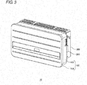
- Fig. 3 is a perspective view obtained by viewing the power conditioner 10 from the front side.
- the fixing plate 200, the heat sink, the accommodation box 102, and the cover 104 are assembled in an arranged manner illustrated in Figs. 1 and 2 .
- the casing 100 which holds the heat sink 150 between itself and the fixing plate 200 is attached to the attachment plate 300.
- Fig. 4 is a perspective view obtained by viewing the fixing plate 200 provided for the power conditioner 10 from the front side.
- Fig. 5 is a perspective view obtained by viewing the fixing plate 200 from the back side.
- the fixing plate 200 has openings 202 in positions corresponding to the radiation fin portions 152 of the heat sink 150, respectively.
- the fixing plate 200 is fixed to the back surface of the accommodation box 102, the radiation fin portions 152 are inserted into the openings 202, respectively and the radiation fin portions 152 are exposed through the openings 202, respectively.
- a plurality of pillar portions 230 are installed to stand up on both sides of each opening 202.
- a latching plate 232 is disposed between every two of the plurality of pillar portions 230.
- the latching plate 232 is supported by the plurality of pillar portions 230, and fixed to ends of the plurality of pillar portions 230.
- the latching plate 232 is latched to an attachment plate-side latching member of the attachment plate 300.
- the power conditioner 10 is attached to the attachment plate 300 in a manner that the latching plate 232 is latched to the attachment plate-side latching member.
- the fixing plate 200 On the back surface of the fixing plate 200, two pillar portions 234 stand up on both sides of the center opening 202.
- a Plate 236 which functions as a reinforcing plate for preventing deformation of the fixing plate 200 is fixed to the ends of the two pillar portions 234.
- the fixing plate 200 further includes a fixing plate-side eave plate 210 disposed above the insertion hole 110 formed in the accommodation box 102.
- Guide pins 220 for guiding the latching plate 232 to the attachment plate-side latching member 330 are provided in external surfaces of the pillar portions 230 disposed on both sides of the power conditioner 10, among the plurality of pillar portions 230.
- the fixing plate 200 includes a bridge portion 240 serving as a strap which extends across the recessed portion 106 for hand's insertion in the accommodation box 102. The user can carry the power conditioner 10 by inserting his or her hand into the recessed portion 106 from the back side of the power conditioner 10 and grabbing the bridge portion 240.
- Fig. 6 is a perspective view obtained by viewing the attachment plate 300 provided for the power conditioner 10 from the front side.
- the attachment plate 300 includes a main plate 302 to be attached to an outer wall, etc.
- the attachment plate 300 has a side plate 304, a top plate 306, and a bottom plate 308 as sub plates.
- the main plate 302 is disposed in a position facing the back surface of the power conditioner 10.
- the side plate 304 is disposed in a position facing the side surface of the power conditioner 10.
- the top plate 306 is disposed in a position facing a top surface of the power conditioner 10.
- the bottom plate 308 is disposed in a position facing a bottom surface of the power conditioner 10.
- the top plate 306 and the bottom plate 308 have mesh portions 340 and 342, respectively, in positions facing the radiation fin portions 152. Since the top plate 306 and the bottom plate 308 are formed in a mesh shape, foreign substances can not reach the radiation fin portions 152.
- the attachment plate 300 further includes an attachment plate-side latching member 330 provided in the main plate 302.
- the latching plate 232 which is the apparatus-side latching member provided in the fixing plate 200 is latched to the attachment plate-side latching member 330.
- the attachment plate-side latching member 330 includes a plurality of hook portions 332, and the latching plate 232 is latched to the plurality of hook portions 332.
- the attachment plate 300 has a guide hole 320 serving as an attachment plate-side guide structure provided in the side plate 304.
- the guide hole 320 guides the apparatus-side latching member to the attachment plate-side latching member 330 by cooperating with the apparatus-side guide structure provided in the side surface of the power conditioner 10, when the power conditioner 10 is attached to the attachment plate 300. More specifically, the guide hole 320 guides the latching plate 232 to the attachment plate-side latching member 330 by cooperating with the guide pin 220 provided in the pillar portion 230 of the fixing plate 200.
- the latching plate 232 is provided in the back surface of the power conditioner 10. Therefore, when the power conditioner 10 is attached to the attachment plate 300, it is difficult for a user to see the latching plate 232.
- the attachment plate 300 further icludes an attachment plate-side eave plate 310 disposed above the insertion hole 110 formed in the accommodation box 102.
- the attachment plate-side eave plate 310 is positioned such that the attachment plate-side eave plate 310 overlaps a fixing plate-side eave plate 210 of the fixing plate 200 when viewed in a vertical direction.
- the fixing plate-side eave plate 210 and the attachment plate-side eave plate stand to face each other and are disposed in a position at which they overlap each other when viewed in the vertical direction.
- a gap may be formed between the end of the eave plate, and the other plate which is not provided with the eave plate.
- rain water which drops from the gap and passes by the radiation fin portion 152 of the heat sink 150 is likely to fall onto the cable disposed in the insertion hole 110. The rain water is likely to move along the cable and invade the casing 100 through the insertion hole 110.
- both of the fixing plate 200 and the attachment plate 300 are provided with respective eave plates, even if a gap exists between one eave plate of the two eave plates and one plate associated with the other eave plate, the other eave plate provided for the other plate can prevent the rain water from dropping from the gap to the cable. Therefore, with the configuration in which both of the fixing plate 200 and the attachment plate 300 are provided with respective eave plates, it is possible to prevent rain water from flowing along the cable and invading the casing 100 from the insertion hole 110.
- Fig. 7 is an enlarged perspective view obtained by viewing, from the back side, the recessed portion 106 for hand's insertion formed in the accommodation box 102 and the bridge portion 240 serving as a strap provided in the fixing plate 200.
- a user can grab the bridge portion 240 by inserting his or her hand into the recessed portion 106 in a direction indicated by an arrow illustrated in Fig. 7 .
- the user can more stably carry the power conditioner 10 compared with a case where the power conditioner 10 is supported only by using the recessed portion 106.
- the fixing plate 200 can be made from a relatively hard material such as iron, when the power conditioner 10 is carried, deformation of the casing 100 can be prevented.
- the female screw 204 is formed in the fixing plate 200
- the female screw may be formed in the casing 100.
- the female screw may be formed in each of the casing 100, the heat sink 150, and the fixing plate 200.
- through holes with no screw threads may be formed in the casing 100, the heat sink 150, and the fixing plate 200, and the heat sink 150 may be held using a bolt and a nut.
- the heat sink 150 may be a radiation plate which does not have the radiation fin portion 152.
- attachment plate-side latching member 330 has a hook
- other structures may be possible as long as the attachment plate-side latching member 330 and the fixing plate-side latching member are latched to each other.
- the latching plate 232 which is the fixing plate-side latching member may have a hook
- the attachment plate-side latching member 330 may have an attachment hole into which the hook is hooked.
Landscapes
- Engineering & Computer Science (AREA)
- Microelectronics & Electronic Packaging (AREA)
- Physics & Mathematics (AREA)
- Thermal Sciences (AREA)
- Cooling Or The Like Of Electrical Apparatus (AREA)
- Connection Of Plates (AREA)
- Arrangement Of Elements, Cooling, Sealing, Or The Like Of Lighting Devices (AREA)
Applications Claiming Priority (1)
| Application Number | Priority Date | Filing Date | Title |
|---|---|---|---|
| JP2012232142A JP6007723B2 (ja) | 2012-10-19 | 2012-10-19 | ヒートシンクを備える機器 |
Publications (2)
| Publication Number | Publication Date |
|---|---|
| EP2723152A2 true EP2723152A2 (fr) | 2014-04-23 |
| EP2723152A3 EP2723152A3 (fr) | 2016-07-13 |
Family
ID=49293488
Family Applications (1)
| Application Number | Title | Priority Date | Filing Date |
|---|---|---|---|
| EP13186344.1A Withdrawn EP2723152A3 (fr) | 2012-10-19 | 2013-09-27 | Appareil équipé d'un dissipateur de chaleur |
Country Status (3)
| Country | Link |
|---|---|
| EP (1) | EP2723152A3 (fr) |
| JP (1) | JP6007723B2 (fr) |
| CN (1) | CN103781333A (fr) |
Cited By (1)
| Publication number | Priority date | Publication date | Assignee | Title |
|---|---|---|---|---|
| WO2019222779A1 (fr) * | 2018-05-25 | 2019-11-28 | Miba Energy Holding Gmbh | Ensemble de puissance comprenant une cloison |
Families Citing this family (3)
| Publication number | Priority date | Publication date | Assignee | Title |
|---|---|---|---|---|
| JP2016021836A (ja) * | 2014-07-15 | 2016-02-04 | 三菱電機株式会社 | パワーコンディショナ |
| JP6822753B2 (ja) * | 2015-03-18 | 2021-01-27 | 積水化学工業株式会社 | 建物の改修方法 |
| JP6799848B2 (ja) * | 2015-10-30 | 2020-12-16 | 株式会社エイテック | 標的システム |
Citations (1)
| Publication number | Priority date | Publication date | Assignee | Title |
|---|---|---|---|---|
| JP2011258874A (ja) | 2010-06-11 | 2011-12-22 | Showa Denko Kk | パワーコンディショナ |
Family Cites Families (9)
| Publication number | Priority date | Publication date | Assignee | Title |
|---|---|---|---|---|
| JPH10240155A (ja) * | 1997-03-03 | 1998-09-11 | Fujitsu General Ltd | 薄形映像機器のスタンド装置 |
| DE29923011U1 (de) * | 1999-12-30 | 2000-02-24 | H.-J. Bernstein GmbH, 32479 Hille | Gehäuse zur Aufnahme elektrischer oder elektronischer Bauteile |
| JP4049722B2 (ja) * | 2003-09-02 | 2008-02-20 | シャープ株式会社 | 壁掛け構造および壁掛け具 |
| JP4803642B2 (ja) * | 2005-05-27 | 2011-10-26 | サミー株式会社 | 遊技機の制御装置 |
| US7180747B2 (en) * | 2005-05-31 | 2007-02-20 | Cheng-Ping Lee | Heat dissipation device for a computer mother board |
| US7355857B2 (en) * | 2006-02-07 | 2008-04-08 | Methode Electronics, Inc. | Heat sink gasket |
| DE102006013017B4 (de) * | 2006-03-20 | 2014-11-06 | R. Stahl Schaltgeräte GmbH | Gehäuse mit Wärmebrücke |
| US8582298B2 (en) * | 2009-06-22 | 2013-11-12 | Xyber Technologies | Passive cooling enclosure system and method for electronics devices |
| CN203562963U (zh) * | 2011-02-08 | 2014-04-23 | 三洋电机株式会社 | 功率调节器 |
-
2012
- 2012-10-19 JP JP2012232142A patent/JP6007723B2/ja active Active
-
2013
- 2013-09-27 CN CN201310451384.4A patent/CN103781333A/zh active Pending
- 2013-09-27 EP EP13186344.1A patent/EP2723152A3/fr not_active Withdrawn
Patent Citations (1)
| Publication number | Priority date | Publication date | Assignee | Title |
|---|---|---|---|---|
| JP2011258874A (ja) | 2010-06-11 | 2011-12-22 | Showa Denko Kk | パワーコンディショナ |
Cited By (1)
| Publication number | Priority date | Publication date | Assignee | Title |
|---|---|---|---|---|
| WO2019222779A1 (fr) * | 2018-05-25 | 2019-11-28 | Miba Energy Holding Gmbh | Ensemble de puissance comprenant une cloison |
Also Published As
| Publication number | Publication date |
|---|---|
| JP6007723B2 (ja) | 2016-10-12 |
| JP2014086459A (ja) | 2014-05-12 |
| EP2723152A3 (fr) | 2016-07-13 |
| CN103781333A (zh) | 2014-05-07 |
Similar Documents
| Publication | Publication Date | Title |
|---|---|---|
| EP2723149B1 (fr) | Plaque de montage à laquelle un appareil est monté, appareil et système | |
| CN106535519A (zh) | 电气设备壳体以及电力转换装置 | |
| US9163637B2 (en) | Fan assembly and fan device thereof | |
| EP2723152A2 (fr) | Appareil équipé d'un dissipateur de chaleur | |
| JP6094452B2 (ja) | 蓄電モジュール | |
| JP6131507B2 (ja) | Ledモジュール及び照明器具 | |
| JP6323780B2 (ja) | 照明器具 | |
| CN203734021U (zh) | 连接器组件 | |
| US20130008903A1 (en) | Casing cover | |
| JP2013016810A (ja) | 放熱装置 | |
| JP6041210B2 (ja) | 光源ユニット及びそれを用いた照明器具 | |
| WO2018150714A1 (fr) | Équipement électrique | |
| JP6440058B2 (ja) | 光源ユニット及び照明器具 | |
| CN102573399A (zh) | 电子装置 | |
| US7198506B2 (en) | Connector | |
| CN104918458B (zh) | 电子设备 | |
| JP5846441B2 (ja) | 電気接続箱 | |
| CN104918455A (zh) | 电子设备 | |
| WO2018150715A1 (fr) | Équipement électrique | |
| CN107949215B (zh) | 显示装置及其壳体结构 | |
| CN107388210A (zh) | 电源装置以及照明器具 | |
| CN107949218B (zh) | 显示装置及其壳体结构 | |
| JP2018060829A (ja) | 電気設備 | |
| JP2015176748A (ja) | 光源ユニット及びそれを用いた照明器具 | |
| TW201320445A (zh) | 電池固定裝置 |
Legal Events
| Date | Code | Title | Description |
|---|---|---|---|
| PUAI | Public reference made under article 153(3) epc to a published international application that has entered the european phase |
Free format text: ORIGINAL CODE: 0009012 |
|
| AK | Designated contracting states |
Kind code of ref document: A2 Designated state(s): AL AT BE BG CH CY CZ DE DK EE ES FI FR GB GR HR HU IE IS IT LI LT LU LV MC MK MT NL NO PL PT RO RS SE SI SK SM TR |
|
| AX | Request for extension of the european patent |
Extension state: BA ME |
|
| PUAL | Search report despatched |
Free format text: ORIGINAL CODE: 0009013 |
|
| AK | Designated contracting states |
Kind code of ref document: A3 Designated state(s): AL AT BE BG CH CY CZ DE DK EE ES FI FR GB GR HR HU IE IS IT LI LT LU LV MC MK MT NL NO PL PT RO RS SE SI SK SM TR |
|
| AX | Request for extension of the european patent |
Extension state: BA ME |
|
| RIC1 | Information provided on ipc code assigned before grant |
Ipc: H05K 7/14 20060101ALI20160603BHEP Ipc: H05K 7/20 20060101AFI20160603BHEP Ipc: H05K 5/02 20060101ALI20160603BHEP |
|
| STAA | Information on the status of an ep patent application or granted ep patent |
Free format text: STATUS: THE APPLICATION HAS BEEN PUBLISHED |
|
| STAA | Information on the status of an ep patent application or granted ep patent |
Free format text: STATUS: THE APPLICATION IS DEEMED TO BE WITHDRAWN |
|
| 18D | Application deemed to be withdrawn |
Effective date: 20170114 |