EP2723256B1 - Ergonomischer beleuchteter gebärmuttermanipulator mit kauter - Google Patents
Ergonomischer beleuchteter gebärmuttermanipulator mit kauter Download PDFInfo
- Publication number
- EP2723256B1 EP2723256B1 EP12802937.8A EP12802937A EP2723256B1 EP 2723256 B1 EP2723256 B1 EP 2723256B1 EP 12802937 A EP12802937 A EP 12802937A EP 2723256 B1 EP2723256 B1 EP 2723256B1
- Authority
- EP
- European Patent Office
- Prior art keywords
- cup
- sound
- manipulator
- anchor
- shaft
- Prior art date
- Legal status (The legal status is an assumption and is not a legal conclusion. Google has not performed a legal analysis and makes no representation as to the accuracy of the status listed.)
- Active
Links
Images









Classifications
-
- A—HUMAN NECESSITIES
- A61—MEDICAL OR VETERINARY SCIENCE; HYGIENE
- A61B—DIAGNOSIS; SURGERY; IDENTIFICATION
- A61B17/00—Surgical instruments, devices or methods
- A61B17/42—Gynaecological or obstetrical instruments or methods
- A61B17/4241—Instruments for manoeuvring or retracting the uterus, e.g. during laparoscopic surgery
-
- A—HUMAN NECESSITIES
- A61—MEDICAL OR VETERINARY SCIENCE; HYGIENE
- A61B—DIAGNOSIS; SURGERY; IDENTIFICATION
- A61B90/00—Instruments, implements or accessories specially adapted for surgery or diagnosis and not covered by any of the groups A61B1/00 - A61B50/00, e.g. for luxation treatment or for protecting wound edges
- A61B90/30—Devices for illuminating a surgical field, the devices having an interrelation with other surgical devices or with a surgical procedure
-
- A—HUMAN NECESSITIES
- A61—MEDICAL OR VETERINARY SCIENCE; HYGIENE
- A61B—DIAGNOSIS; SURGERY; IDENTIFICATION
- A61B17/00—Surgical instruments, devices or methods
- A61B17/00234—Surgical instruments, devices or methods for minimally invasive surgery
- A61B2017/00292—Surgical instruments, devices or methods for minimally invasive surgery mounted on or guided by flexible, e.g. catheter-like, means
- A61B2017/003—Steerable
- A61B2017/00318—Steering mechanisms
- A61B2017/00323—Cables or rods
-
- A—HUMAN NECESSITIES
- A61—MEDICAL OR VETERINARY SCIENCE; HYGIENE
- A61B—DIAGNOSIS; SURGERY; IDENTIFICATION
- A61B17/00—Surgical instruments, devices or methods
- A61B2017/0042—Surgical instruments, devices or methods with special provisions for gripping
- A61B2017/00429—Surgical instruments, devices or methods with special provisions for gripping with a roughened portion
- A61B2017/00433—Surgical instruments, devices or methods with special provisions for gripping with a roughened portion knurled
-
- A—HUMAN NECESSITIES
- A61—MEDICAL OR VETERINARY SCIENCE; HYGIENE
- A61B—DIAGNOSIS; SURGERY; IDENTIFICATION
- A61B17/00—Surgical instruments, devices or methods
- A61B2017/0042—Surgical instruments, devices or methods with special provisions for gripping
- A61B2017/00455—Orientation indicators, e.g. recess on the handle
-
- A—HUMAN NECESSITIES
- A61—MEDICAL OR VETERINARY SCIENCE; HYGIENE
- A61B—DIAGNOSIS; SURGERY; IDENTIFICATION
- A61B18/00—Surgical instruments, devices or methods for transferring non-mechanical forms of energy to or from the body
- A61B18/04—Surgical instruments, devices or methods for transferring non-mechanical forms of energy to or from the body by heating
- A61B18/12—Surgical instruments, devices or methods for transferring non-mechanical forms of energy to or from the body by heating by passing a current through the tissue to be heated, e.g. high-frequency current
- A61B18/14—Probes or electrodes therefor
- A61B2018/1405—Electrodes having a specific shape
- A61B2018/1412—Blade
-
- A—HUMAN NECESSITIES
- A61—MEDICAL OR VETERINARY SCIENCE; HYGIENE
- A61B—DIAGNOSIS; SURGERY; IDENTIFICATION
- A61B90/00—Instruments, implements or accessories specially adapted for surgery or diagnosis and not covered by any of the groups A61B1/00 - A61B50/00, e.g. for luxation treatment or for protecting wound edges
- A61B90/30—Devices for illuminating a surgical field, the devices having an interrelation with other surgical devices or with a surgical procedure
- A61B2090/306—Devices for illuminating a surgical field, the devices having an interrelation with other surgical devices or with a surgical procedure using optical fibres
Definitions
- U.S. Pat. No. 5,394,863 described a pipe-like optical light guide with a hollow cup to transmit light through the vaginal fornices for surgical and medical procedures. While this invention recognized the utility of providing light to the fornices, it failed to provide a means to actively engage, pivot or manipulate the cervix and uterus. Further, it failed to provide an ergonomic handle to enable surgical control of the specimen. This patent appears to have never led to a commercially available product and the patent was prematurely abandoned. This patent cited eight predecessor patents ( U.S. Pat. Nos.
- U.S. Pat. Nos. 5,520,698 , 5,643,285 and 5,840,077 described methods and a uterine manipulation assembly for laparoscopic hysterectomy.
- This disclosure also provided a cup for cervical engagement located at the end of a hand-controlled device. Movement of this cup was achieved by the counterintuitive side to side rotation of the proximal handle, which is perpendicular to the shaft of the device, leading to up and down movement of the distal cup. This means of moving the distal cup along with the attached cervix has proved to be surprisingly difficult for operating room staff routine implementation.
- uterine manipulators While several more uterine manipulators have been offered as commercial products or described in patent disclosures, they essentially involve non-ergonomic, counterintuitive handles (not co-linear with the device shaft) which function similarly to the RUMI® Manipulator.
- the manipulator comprises a rigid manipulation shaft which is used as a central assembly axis upon which the parts of a surgical instrument are centered.
- a manipulator tube surrounds the manipulation shaft such that there is no empty space between the manipulator tube and the manipulation shaft, thereby indicating a close fit between the manipulation shaft and the manipulator tube assembled around it.
- a cervical cup is molded to the outside of manipulator tube.
- the manipulation shaft has an inflatable balloon located at the distal end of the manipulation shaft. The distal end of the manipulation shaft with its larger rounded tip and balloon cannot pass back through the tight channel in manipulator tube given the tight fit between the manipulation shaft and the manipulator tube.
- US 2005/0187561 A1 discloses a delivery device for transcervical delivery of material intended to occlude fallopian tubes where they meet the uterus.
- the delivery device has a shaft which has an introducer tip at its distal end and a handle at its proximal end.
- Two catheter insertion holes are located at the most proximal portion of the handle, and each of the catheter insertion holes is coupled to a respective catheter channel which passes through the handle, down the shaft, and exits the shaft very close to the distal introducer tip.
- a delivery device stabilizer is movable up and down the shaft.
- the catheter insertion holes are significantly wider than the diameter of the shaft.
- a double-lumen catheter, which goes into the delivery device, has a balloon near a distal delivery end.
- the catheter also has two fittings at its proximal end: a fitting for connection to a fluid source which can inflate the balloon; and a fitting for connection to a flowable occlusion material.
- the distal end of the catheter must be inserted into one of the catheter insertion holes on the proximal end of the delivery device.
- the fittings and balloon of the catheter could not be passed proximally into the openings on the distal end of the delivery device.
- US 2010/0106163 A1 discloses a uterine manipulator assembly that is based on an elongate arcuate shaft. A detachable cervical cup and a detachable tip may be selectively coupled to a distal end of the shaft.
- the device includes a hook element provided with at least one hook which is connected via a rod, which is guided in a shaft, to a grip end provided at a proximal end of the device in such a manner that the hook can be pivoted in and out.
- a glide element which is guided in a sliding manner on the shaft in the longitudinal direction thereof is provided at its distal end with an approximately bell-shaped expansion.
- a uterine manipulator includes a sound and a body.
- the sound has a selectively actuatable anchor disposed proximate a distal end and an operating mechanism spaced from the anchor for controlling actuation of the anchor.
- the body has a passage therethrough adapted to receive the sound passed proximally through the body to a position in which the operating mechanism is accessible proximally of the body and the anchor extends distally.
- a uterine manipulator in another embodiment, includes a generally straight, elongate body having a longitudinal axis and defining a substantially linear passageway therethrough, terminating at an opening in the cup; a handle on one end of the body having a longitudinal axis substantially co-axial with the longitudinal axis of the body; a cup on an opposite end of the body; and a sound having an elongate shaft receivable in the substantially linear passageway of the elongated body and a distal tip protruding from the opening in the cup.
- the cup has an opening angled relative to the longitudinal axis of the elongate body.
- the two main design goals for this invention were to develop a safe and truly effective technology for use under relevant surgical conditions, and then to provide a product that is easily learned and successfully deployed by surgeons and their assistants without requiring exhaustive training.
- the technology is designed to be more readily installed, intuitively obvious to position, and comfortable to hold.
- a compelling feature of this invention, to enable ease of installation, is the provision of an isolated slender customized sound which is readily installed through the cervix into the uterus. This compact sound acts as a guide over which the cervical engaging cup can be subsequently passed.
- the ability to install the sound alone readily enables its installation into the uterus under direct visualization within the vagina. This separate sound also makes its secure engagement to the uterus easy by turning the knurled knob to rotate the anchor.
- This novel technology consists of four primary components, which are further provided in a variety of sizes to accommodate variations in patient anatomy.
- An ergonomic hand-held cervical engagement device with a custom co-axial handle at its proximal end is connected by an atraumatic shaft incorporating a sliding flexible vaginal occluder to an angled cup to receive the cervix at its distal end. Passageways within this cervical engagement device provide for receipt of additional components and features.
- an angled shaft (or sound) is provided to pass through the cervical engagement device, through the cervical canal and into the cavity in the body of the uterus, where a rotational anchor can be deployed to secure the shaft to the uterus. Additional options provided with this technology include the provision of light at the distal cervical cup to transilluminate and better visualize tissues of the vaginal fornix area and an energized dissection means to help dissect the uterus from the vagina.
- a ridge on the handle of the cervical engagement device indicates the direction of the angled cervical cup and angled shaft of the sound.
- the cervical cup and angled sound rotate to pivot the uterus in the direction of the indicator ridge.
- the indicator ridge is oriented up, the body of the uterus is pivoted up (i.e., ante flexed) to provide access for the posterior colpotomy (i.e., vaginal incision) dissection.
- the ridge is down, the uterus is retroflexed to enable development of the bladder flap and anterior colpotomy; indicator ridge orientation to either side, enables ipsilateral uterine body pivoting for contra-lateral uterine blood vessel transillumination and dissection, along with colpotomy completion.
- the uterine body pivots towards the patient's right side, exposing the left side uterine arteries and veins (and potentially transilluminating them) and distracting these important blood vessels away from the left ureter.
- this simple technique of rotating the coaxial handle to displace the uterus reduces the potential risk of ureteral injury during dissection.
- this same maneuver can expose the left uterine arteries, move them away from the left ureter and enable completion of the colpotomy.
- the cervical engagement devices can be constructed of mostly common surgical plastics with different sized distal cervical cups.
- distal cervical cups having inside diameters of 30, 35, or 40 mm could accommodate the range of cervical sizes most commonly encountered in hysterectomy surgery.
- the unique angled sounds offered in this invention can be reusable implements with customized angled shafts constructed of cleanable and resterilizable surgical quality metal; the distal ends of these sounds should have shaft diameters of 5 mm or less to readily pass through the cervical canal and be offered different lengths (e.g., commonly from 6 to 7 to 8 cm) to span the various lengths of patient's uterine bodies.
- a reusable, resterilizable metal and fiber optic vaginal illumination device can be employed or the illumination components can be integrated within the cervical engagement device.
- the energy based dissection component can be reusable or single-use and integrated within the cervical engagement device.
- each cervical engagement device can also incorporate a passageway leading from its proximal end to a sealed transparent section in the distal cup.
- This passageway is parallel to the passageway for the angled sound and can be used to receive and secure a vaginal illumination device.
- This vaginal illuminator has a fan shaped, metal and fiber optic distal end, a shaft, and a proximal attachment feature.
- a standard threaded coupler is located at its proximal end to enable connection to a standard surgical light source. Light passes from the light source, through the light bundle, into the proximal end of the vaginal illuminator and out its distal end where it passes through the transparent section in the distal cervical cup.
- vaginal illuminator is an option that can be used at the surgeon's discretion with this technology for the provision of transillumination light delivered through the distal cervical cup.
- Using light to transilluminate or pass through targeted tissues is a common practice in minimally invasive surgery.
- Vaginal illumination is commonly employed in many routine gynecologic diagnostic and therapeutic interventions.
- transillumination via the fiber optic vaginal illuminator through the transparent seal of the distal cervical cup can make identifying the cervical cup edges and the targeted fornices much easier.
- This transillumination technique may allow the surgical team to identify internal tissue structures, such as blood vessels, that lie within solid tissue planes. With this lighting option, important internal tissue elements can be differentiated through direct video imaging.
- the resection or removal of the uterus requires the cervical region of the uterus to be dissected free or amputated from its attachments at the upper forniceal area of the vagina.
- This dissection is typically approached from one of two directions: “from below” or “from above.” If the surgeon stands down between the patient's legs and passes dissecting instruments from outside towards the inside up through the vagina, as in a vaginal hysterectomy, this dissection is considered to be “from below.”
- the instruments placed “from above” the instruments are oriented in the preferred direction from the inside of the peritoneal cavity towards the vagina, as in traditional open surgery or in total laparoscopic hysterectomy, the surgeon can stay at the patient's side adjacent to the abdomen.
- this unique approach facilitates the benefits and convenience of providing the dissection coming in from below along with the safety and ergonomics of viewing the dissection from the above, laparoscopic perspective.
- this technology provides for direct dissection of the vaginal cuff up through the vagina, while simultaneously viewing and performing laparoscopic surgery from above.
- the cervical engagement device with its angled sound along with the optional vaginal illuminator and integrated energized dissection features provide a compellingly improved alternative technology that has been favorably received by reviewing surgeons for enhanced uterine manipulation during minimally invasive gynecologic procedures.
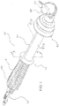
- a perspective view of a uterine manipulator 10 is shown, comprised of a sound 20 and a light wand 30 accepted within and housed by a device 40.
- the sound 20 and light wand 30 are generally manufactured such that they are reusable and preferably comprised of rigid, sterilizable, and cleanable materials such as stainless steels and the like.
- the device 40 is typically disposable and generally comprised of sterilizable molded polymers.
- a proximally located textured handle 41 imparting a tactile surface for ease of physical manipulation of manipulator 10 and device 40
- an indicator ridge 42 to delineate manipulator 10 orientation within a surgical field
- a centrally situated shaft or body 43 providing support to and visual indication of insertion depth for the manipulator 10
- a distally positioned occluder 50 to maintain intra-peritoneal gas pressure within the surgical field
- a distally sited cup 60 for cervical engagement are a proximally located textured handle 41 imparting a tactile surface for ease of physical manipulation of manipulator 10 and device 40
- an indicator ridge 42 to delineate manipulator 10 orientation within a surgical field
- a centrally situated shaft or body 43 providing support to and visual indication of insertion depth for the manipulator 10
- a distally positioned occluder 50 to maintain intra-peritoneal gas pressure within the surgical field
- a distally sited cup 60 for cervical engagement.
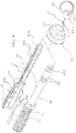
- FIG. 2 shows an exploded perspective view of the uterine manipulator 10 with the sound 20 and light wand 30 removed from the device 40.
- the sound 20 is received through the distal end of the device 40 while the light wand 30 is received through the proximal end of the device 40.
- the sound 20 is inserted distally through a sound port 61, which is a substantially linear passageway formed through the device body, such that a cervical stop 21 rests firmly against a stop ledge 62 provided in the cup 60.
- a sound port 61 which is a substantially linear passageway formed through the device body, such that a cervical stop 21 rests firmly against a stop ledge 62 provided in the cup 60.
- an anchor nut 22 protrudes from textured handle 41 as opposed wedge stops 23a engage with a latch 44.
- the light wand 30 is insertable proximally into the device 40 through a wand port 45, in the textured handle 41, best shown in FIG. 2A , until a winged snap 31 engages with receiving edges 46 of the wand port 45.
- a wand fan 32 mates adjacent to a window 70 within the cup 60.
- FIG. 2A is a proximal view of the device 40 and highlights a latch port 49 through which the latch 44 and the sound 20 subsystem shown in FIG. 2 protrude from the textured handle 41 and the wand port 45 through which the light wand 30 is introduced and engages with receiving edges 46.
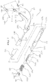
- FIG. 3 is an orthogonal section view taken along sectioned lines 3-3 of the uterine manipulator 10 of FIG. 1 showing the positions of the assembled sound 20 and light wand 30 within the device 40.
- the sound 20 is located vertically above the light wand 30.
- the cervical stop 21 of the sound 20 is engaged with the stop ledge 62 in the cup 60 and the wand fan 32 is nested adjacent to the window 70 within the cup 60.
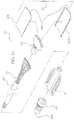
- FIG. 4 Shown in FIG. 4 is an exploded perspective view of the device 40.
- the device 40 is purposefully meant to be supplied as a sterile, one-time use product.
- a left handle 47 and a right handle 48 are assembled to capture tabs 44a of the latch 44 within left receptacles 47A of the left handle 47 and symmetrically opposed right receptacles (not shown) of the right handle 48.
- the left handle 47 and right handle 48 are typically made from an opaque medical grade plastic and produced from an injection molding process and assembled and retained via a mechanical force fit, ultrasonic welding process, or adhesives.
- the latch 44 is preferably made from a formed stainless steel sheet, but can be made from a resilient medical grade polymer.
- the occluder 50 is slid over the shaft 43 such that a bore 51 of the occluder 50 engages with ridges 43a of the device 40 and creates an airtight seal around the shaft 43.
- the occluder 50 can be slid back and forth and positioned along the shaft 43 as dictated by the surgical procedure.
- the occluder 50 is made of a transparent or translucent molded flexible polymer such as medical-grade silicone.
- the window 70 is disposed in the cup 60 such that a front face 71 of the window 70 is flush with a distal face 63 of the cup 60.
- the joint between the cup 60 and window 70 is preferably hermetic to prevent the introduction of bodily fluids in proximity to the heat intense areas of a wand fan 32 of the light wand 30, and can be accomplished via mechanical press fits, gasketing, or adhesive fillers.
- the window 70 is produced via injection molding processes and is made of a heat resistant transparent material such as polyetherimide (commercially available from GE Plastics under the trade name Ultem®) or from other high performance transparent acrylics.
- the cup 60 is similarly made from an injection molded, but opaque heat resistant plastic such as Ultem®.
- the device 40 can be manufactured and offered with a variety of cups 60 to accommodate a variety of cervical sizes. For convenience in identification, the respective cups 60 may be marked with the appropriate nomenclature via a marking 65 provided on the cup 60.
- the assembled cup 60 with window 70 are inserted over a head 43b of the body 43 such that the window 70 is positioned coplanar with, but opposite from, the indicator ridge 42 of the device 40.
- the cup 60 is preferably fixedly and permanently attached to the shaft 43 during a surgical procedure, for example, via a mechanical force fit or with the aid of adhesives.
- the sound 20, a subsystem of the uterine manipulator 10, is detailed.
- the sound 20, as described, is preferably meant to be supplied as a sterile, cleanable, and reusable product that is used to probe and couple to the uterine structures. Additional operational characteristics of the sound 20 are explained below.
- FIG. 5 is an overhead perspective view of the sound 20 initially detailed in FIG. 2 .
- the sound 20 is centrally comprised of a substantially cylindrical keyed shaft 24, which distally supports an angled shaft 25 and a rotational anchor 26.
- a guide shaft 23, and anchor nut 22, and a cap 28 are disposed proximally on the sound 20.
- the sound 20 can be manufactured and offered with a variety of angled shafts 25 to accommodate the array of anatomical differences.
- the respective angled shafts 25 may be marked with the appropriate nomenclature via a marking 21A provided on the cervical stop 21.
- a marking 23N may be applied to the guide shaft 23.
- a clockwise rotation 22C of the anchor nut 22, as viewed from the anchor nut 22 end of the sound 20, will cause a drive screw 29 and attached drive wire 27, more readily viewed in FIG. 6 , to retract and induce a pulling force on an anchor barrel 80 housed within rotational anchor 26.
- This pulling will cause the rotational anchor 26 to follow rotation direction 26C, pivoting about a pivot point, and move perpendicular to the angled shaft 25.
- rotating the anchor nut 22 in the opposite direction will impart a pushing force on the anchor barrel 80, causing the rotational anchor 26 to return to its original position aligned with the angled shaft 25.
- FIG. 6 is an underside perspective view of the sound 20 of FIG. 5 . From this perspective, proximally, the drive screw 29 is shown. As described above, the drive screw 29 is engaged with the anchor nut 22 to push or pull the drive wire 27 which engages with and directs the rotational anchor 26. The drive wire 27 emanating from the drive screw 29 is delivered through the guide shaft 23 via a wire channel 23B, retained by retaining tabs 23C and allowed cleaning access via cleaning troughs 23D. The wire 27 also passes through the keyed shaft 24 via a wire channel 24A, where it is retained by retaining tabs 24B and allowed cleaning access via cleaning troughs 24c.
- the wire also passes through the angled shaft 25 via a wire channel 25A, where it is retained by retaining tabs 25B and allowed cleaning access via cleaning troughs 25C.
- the wire 27 connects to the rotational anchor 26.
- a clockwise rotation 22C of the anchor nut 22 as viewed from the anchor nut 22 end of the sound 20, will cause the drive screw 29 and its attached drive wire 27 to retract in pull direction 27A and induce a pulling force on the anchor barrel 80 housed within rotational anchor 26 and cause the rotational anchor 26 to follow rotation direction 26c and move perpendicular to the angled shaft 25.
- rotating the anchor nut 22 in the opposite direction will return the rotational anchor 26 to its original position parallel to the angled shaft 25.
- using a reverse threaded anchor nut 22 could provide for opposite actuation between the perpendicular and aligned positions.
- FIG. 7 is an exploded perspective view of the sound 20 of FIG. 5 wherein the components and assembly order are detailed.
- the keyed shaft 24 preferably is manufactured from a rigid sterilizable material, such as stainless steel, and is connected to the angled shaft 25 via a distal boss 24D which is inserted into a receptacle housing 25D.
- the angled shaft 25 preferably is also of a non-corrosive, biocompatible material similar to the keyed shaft 24.
- the assembled keyed shaft 24 and angled shaft 25 are further assembled to the guide shaft 23 wherein a proximal boss 24E is retained in a receiving bore 23E.
- the guide shaft 23 is also favorably selected from similar non-corrosive, biocompatible material.
- the keyed shaft 24, angled shaft 25, and the guide shaft 23 are permanently joined to form a unitary boss, e.g., via a welding or brazing process, although they may be coupled via other means.
- the drive wire 27 is a common non-corrosive, biocompatible material such as stainless steel wire and is inserted into a wire bore 29a of the drive screw 29 and permanently attached via welding or brazing.
- the drive screw is typically made from a commercial stainless steel with a common industrial thread 29b.
- the assembled drive wire 27 and drive screw 29 are delivered through the previously assembled guide shaft 23, keyed shaft 24, angled shaft 25 by communicating the drive wire 27 through the wire channel 23B, wire channel 24A, and wire channel 25A, correspondingly, such that a guide surface 29C of the drive screw 29 is in contact with a drive channel 23F, more effectively conveyed in FIG. 8 , of the guide shaft 23.
- the anchor nut 22 which also can be made from a commercial, non-corrosive, biocompatible material such as stainless steel, contains an internal thread 22A that mates with thread 29B of drive screw 29 and external knurling 22B to aid in digital manipulation in typical wet, slippery surgical cases.
- the anchor nut 22 is threaded onto the drive screw 29, over a retaining shaft 23G of the guide shaft 23 and secured with the cap 28 by inserting a cap pin 90 through a pin bore 28A in the cap 28 and through a subsequent pin bore 23H in the proximal end of the retaining shaft 23G of the guide shaft 23.
- the cap 28 and cap pin 90 may be of a commercial, non-corrosive, biocompatible material such as stainless steel.
- the free end of the drive wire 27 is passed through a wire hole 81 in the anchor barrel 80 and secured flush via welding or brazing.
- the anchor barrel 80 which can be made from stainless steel and is in all aspects similar to a common dowel pin, protrudes from the angled shaft 25 in proximity to a link receptacle 25E.
- the anchor barrel 80 is guided into a barrel bore 26A of rotational anchor 26 such that the anchor barrel 80 rests central to the rotational anchor 26.
- a dowel pin 100 is pressed into and through a dowel bore 25F of the angled shaft and through a shaft bore 111 of an anchor link 110 waiting in the link receptacle 25E of the angled shaft 25.
- the anchor link 110 is typically fabricated from a rigid material such as stainless steel and provides a means to allow the rotational anchor 26 to pivot while remaining attached to the angled shaft 25.
- a link bore 26b of the rotational anchor 26 is positioned concentric to an anchor bore 112 of the anchor link 110 and a dowel pin 100 is pressed through to retain the rotational anchor 26 while still allowing rotation.
- FIG. 8 is an orthogonal cross sectional view of the sound 20 taken along lines 8-8 of FIG. 5 further illustrating the sound 20.
- the rotational anchor 26 is held by both the anchor barrel 80, which is fixedly attached to the drive wire 27, and the anchor link 110, which is secured by the dowel pin 100, relative to the angled shaft 25.
- the anchor link 110 is secured to the angled shaft by the dowel pin 100.
- the angled shaft 25 is oriented and secured to the keyed shaft 24 which is subsequently oriented and secured to the guide shaft 23, which houses the drive screw 29 in the drive channel 23F.
- the thread 29B of the drive screw 29 mates with the internal thread 22A of the anchor nut 22 and is secured to the retaining shaft 23G of the guide shaft 23 via the cap pin 90 which is pressed through the cap 28 and subsequently through the guide shaft 23.
- the drive wire 27 is fed through the angled shaft 25, the keyed shaft 24, and the guide shaft 23 and securely fastened within the wire bore 29A of the drive screw 29.
- clockwise rotation 22C of the anchor nut 22 will cause the drive screw 29 and its attached drive wire 27 to retract in pull direction 27A and induce a pulling force on the anchor barrel 80 housed within rotational anchor 26 to cause the rotational anchor 26 to follow rotation direction 26C and move perpendicular to the angled shaft 25.
- rotating the anchor nut 22 in the opposite direction will return the rotational anchor 26 to its original position aligned with the angled shaft 25.
- the sound 20 distally enters the device 40 through the cup 60, transits the shaft 43 via a passageway in the shaft, engaging the latch 44, and exits the textured handle 41.
- FIG. 9 shows the sound 20 as it enters the device 40 through the sound port 61 of the cup 60.
- the keyed shaft 24 is housed within the shaft 43 and the anchor nut 22 protrudes from the textured handle 41 via the latch port 49.
- FIG. 10 illustrates the insertion progression of the sound 20 through the device 40 wherein the sound is advanced in direction 120 such that the activation wedge 23J of the guide shaft 23 engages the ramp 44B forcing the latch 44 to flex in direction 44C providing physical resistance and subsequent tactile feedback of sound 20 engagement with the latch 44 of device 40.
- FIG. 11 illustrates the next sequence of advancing the sound 20 through the device 40.
- the sound 20 has further advanced through the device 40 in direction 120 such that, distally, the cervical stop 21 of the sound 20 rests firmly against stop ledge 62 in the cup 60, and proximally, the activation wedge 23J of the guide shaft 23 has cleared the ramp 44B of the latch 44.
- the latch 44 returns to its normal position through direction 44D and latch catch 23K rests within latch recess 44E such that a shaft stop 23M interfaces with a sound stop 44F, physically locking the sound 20 within the device 40. In this position, inadvertent decoupling of the subsystems while in use is prevented. Removal of the sound 20 from the device 40 is accomplished by simply lifting the latch 44 to disengage the latch 44 by allowing the latch recess 44E to clear the latch catch 23K so that sound 20 may be extracted from the distal end of device 40.
- the light wand 30 subsystem is detailed in FIGS. 12 through 14 .
- the light wand 30 is used to transilluminate the vaginal fornices during dissection to help visualize the internal structure of the area being dissected. Vascular structures are highlighted with the use of the light wand 30 and can help the surgeon choose satisfactory areas to perform the dissection to reduce bleeding.
- the light wand 30 is intended to be a rigid, cleanable, and reusable component that is selectively received in and removed from the device 40. It preferably is made from robust sterilizable materials like medical grade stainless steels. In other embodiments, the light wand 30 may be fixed in the device 40.
- FIG. 12 is a perspective view of the light wand 30 detailing the components used in the assembly of said subsystem.
- the wand fan 32 Distally oriented to the subsystem is the wand fan 32, comprised of an upper half 32A and a lower half 32B, which are coupled to the fan coupler 33.
- the fan coupler 33 or any other component of the light wand 30 may be permanently inscribed with a marking 33A to provide the surgeon a visual cue to aid in the insertion of the light wand 30 into the device 40.
- a wand shaft 34 is connected to the fan coupler 33, and a winged snap 31 is attached over the wand shaft 34 in a majoritively proximal location.
- An input adapter 35 is attached proximally to the wand shaft and is used to provide a mating thread for attachment to many commercially available fiber optic light sources such as a Karl Storz Xenon 300 manufactured by Karl Storz GmbH & Co. KG, Tuttlingen, Germany.
- FIG. 13 is an orthogonal section view taken along lines 13-13 of FIG. 12 further indicating the component structure of the light wand 30.
- an optical bundle 36 is centrally housed within the wand shaft 34. The proximal end of the bundle mates flush with an input face 35A of the input adapter 35. The bundle funnels through the fan coupler 33 and the distal end is flush with an exit face 32C of the wand fan 32.
- FIG. 14 is an exploded perspective view of the light wand 30 that illustrates the components and assembly of said subsystem.
- the wand fan 32 Distally oriented to the subsystem is the wand fan 32, comprised of the upper half 32A and the lower half 32B, which are coupled to the fan coupler 33 for example, via a welding, brazing, or adhesive process.
- the upper half 32A and lower half 32B of wand fan 32 and the fan coupler are typically manufactured from a rigid biocompatible material such as stainless steel or the like.
- the fan coupler 33 is fixedly joined to a similarly biocompatible wand shaft 34, preferably by a welding, brazing or adhesive process.
- a winged snap 31 is fixed to the wand shaft 34, preferably by a welding, brazing or adhesive process.
- the input adapter 35 preferably made from stainless steel, is fixed to the proximal end of the wand shaft 34 and completes the external structure of the light wand 30 subsystem.
- the optical bundle 36 is packed within the wand shaft 34, and made flush with the input face 35A of the input adapter 35 and the exit face 32C of the wand fan 32.
- the optical bundle 36 is most typically comprised of a group of tightly packed optical fibers that are polished at each end to maintain optical efficiency and prevent light loss.
- the optical bundle 36 may be secured within the light wand 30 using optical adhesives.
- FIGS. 15 through 17 are orthogonal section views taken along lines 15-15 of FIG. 1 and are useful to detail the introduction of the light wand 30 subsystem into the device 40 subsystem. For clarity, the sound 20 subsystem is not shown.
- the light wand 30 is intended to pass through the device 40 and rest in proximity to the window 70 of the cup 60 such that optical efficiency is maintained and light loss is avoided as light emitted from the exit face 32C passes through the window.
- the light wand 30 has been introduced wand fan 32-first into the wand port 45, which is a passageway extending through the device 40, along direction 37 shown in FIG. 16 , such that the wand fan 32 is disposed in the fan cavity 64 of the cup 60.
- the light wand 30 progresses further into the device 40 via direction 37 until the winged snap 31 interfaces with the receiving edges 46 of the wand port 45.
- spring arms 31B compress in direction 31C allowing ramp tips 31D to engage with the receiving edges 46 and further compress the spring arms 31B to allow the winged snap 31 access into the wand port 45.
- FIG. 17 shows that continued insertion of the light wand 30 into the device 40 causes the wand fan 32 to stop against the window 70 such that the exit face 32C of the wand fan 32 is adjacent to, and preferably in intimate contact with, a rear face 72 of the window 70.
- the exit face 32C's contact with, or adjacency to, the rear face 72 ensures maximum light transmissivity and minimizes optical losses.
- the ramp tips 31 D clear the receiving edges 46 of the wand port 45 allowing the spring arms 31B to return to their normal position through direction 31E and subsequently capturing the winged snap 31 within the wand port 45 by the nesting of receiving troughs 31F inside the receiving edges 46 of the wand port 45.
- the light wand 30 is retained in the device 40 until the spring arms 31B are compressed to unlatch the receiving troughs 31F from the receiving edges 46.
- FIGS. 18 through 24 employ a variety of orthogonal anatomical views, also known as sagittal views, and enlarged detail views, to highlight the preferred use of the uterine manipulation system 10 in a surgical field.
- the uterine manipulation device 10 is used to provide support for, retention of, and dissection assistance with processes associated with hysterectomies.
- FIG. 18 is an orthogonal, midline anatomical view, also known as a sagittal view, showing a retractor 160 maintaining an opening and line of sight into a vaginal canal 130.
- the sound 20 is inserted through the vaginal canal 130 such that the cervical stop 21 rests against an external cervical os 140 and the angled shaft 25 enters the uterus 150.
- the sound 20 is used to probe the cervix and retain the uterus 150 for removal after a uterine dissection.
- the rotational anchor 26 described above is actuated to its perpendicular position to serve these purposes.
- the invention utilizes the novel rotational anchor 26 illustrated and described previously, other anchors could be used. Any selectively actuatable device that can be readily inserted into the uterus and then expanded, including a conventional device, may be used.
- FIG. 19 is an enlarged detail view of the proximal end of FIG. 18 showing the method of engagement of the sound 20.
- the anchor nut 22 is moved in a clockwise rotation 22C, as viewed from proximal end, while the orientation of the sound 20 is maintained in relation to the anatomy.
- the result of this rotation is shown in FIG. 20 .
- FIG. 20 shows that the rotational anchor 26 is moved in the rotation direction 26C such that the rotational anchor 26 is deployed and anchor fingers 26D engage the endometrial lining 151 of the uterus 150.
- the anchor nut 22 activated in FIG. 19 deploys the rotational anchor 26 such that it is, for the most part, perpendicular to the angled shaft 25.
- FIG. 21 shows the sound 20 in position such that the actuated rotational anchor 26 is nested in the uterus 150. Also in this Figure, the device 40 is introduced into the vaginal canal along direction 131 with the sound disposed in the sound port.
- the retractor 160 may be used as a guide to aid in insertion of the device 40.
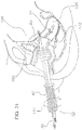
- FIG. 22 is a sagittal view depicting the device 40 further inserted into the vaginal canal 130 until the cup 60 meets and envelops the cervix 170, resting in the vaginal fornix 132.
- FIG. 23 is yet another sagittal view showing the device 40 fully connected with the sound 20. Also in this Figure, the occluder 50 is advanced into the vaginal canal 130 in direction 52 so as to seal the vaginal canal 130 to maintain intra-peritoneum pressure.
- FIG. 23A is a frontal anatomical section, or a coronal view, illustrating the rotation of the device 40 along direction 121, i.e., about the longitudinal axis of the device 40, within the vaginal canal 130. Because the cup 60 contacting the cervix 170 is angled relative to the longitudinal axis of the device, such rotation imparts a right lateral displacement 153 of the uterus 150 (from the patient's perspective) creating a margin of safety between a left ureter 220, and a left uterine artery 152 in preparation for a left lateral colpotomy. Rotating device 40 in the opposite direction would consequently provide for a left lateral displacement of the uterus 150 (from the patient's perspective) a right lateral colpotomy.
- FIG. 24 is a sagittal view wherein the device 40 has been rotated substantially 180-degrees in direction 121, i.e., about the longitudinal axis of the device 40, to reposition the uterus 150 in retroflexion. In this position, additional surfaces of the uterus are readily accessible to a surgeon.
- the uterine manipulator 10 of the present invention allows for repositioning of the uterus 150 in any desirable position through rotation about a single axis, which is the longitudinal axis of the device.
- a positive pressure is maintained between the cup 160 and the uterus 150, but the cup 60 will rotate relative to the uterus 150.
- the sound 20 also will rotate relative to the uterus 150, as it is fixed relative to the cup 60.
- the rotational anchor 26 preferably has smooth surfaces, to facilitate this relative movement and prevent injury within the uterus 150.
- FIG. 24 also illustrates the incorporation of the light wand 30 into the device 40.
- Light 180 is passed through the system via the light wand 30 to illuminate the vaginal fornix 132 through the abdominal cavity 190 to aid in the colpotomy.
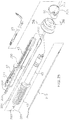
- FIG. 25 is an exploded perspective view of an embodiment incorporating an integrated light pipe 200, similar to the light wand 30, and cautery wand 210.
- the light pipe 200 is permanently captured between the assembled left handle 47 and right handle 48 such that the proximal face 201 is flush with the entry port 203 of the adapter halves 204, that when assembled serve as the connection point for most commercial light sources.
- the light pipe 200 proceeds through the shaft 43 and cup 60 until the distal face 202 is flush with and sealed tightly within a light port 205 of the cup 60.
- the light pipe 200 is typically molded from optically clear polymers such as medical grade polymethyl methacrylate (PMMA) acrylic whose end faces are highly polished to provide for maximum light transmissivity.
- PMMA polymethyl methacrylate
- a powered light source may be provided to emit light proximate the cup 60.
- a Light Emitting Diode could be provided in the cup 60 or a battery-operated light source could be provided, with batteries disposed in the device 40.
- the cautery wand 210 is similar to the likes of commercially available wands such as the E1551G Blade Electrode from ValleyLab of Boulder, Colo., and is simply inserted through a wand port 211, traverses the shaft 43 and exits an electrode port 212 in the cup 60. Any known cautery may be used.
- FIG. 26 is an assembled orthogonal section view taken along lines 26-26 of FIG. 25 illustrating the integration of the light pipe 200 within the textured handle 41 of the device 40 where the light pipe 200 is fixedly located coplanar and adjacent to the sound 20 such that the proximal face 201 is flush with the entry port 203 and, similarly, the distal face 202 is flush with the light port 205.
- the cautery wand 210 Situated immediately below the light pipe 200 is the cautery wand 210 that is readily inserted through the wand port 211, traverses a wand channel 215, and exits the electrode port 212 through the cup 60.
- the cautery wand is movable in the wand channel 215, allowing linear motion in direction 216, thereby making a cautery tip 213 protuberate only at the surgeon's discretion or when surgical conditions dictate.
- FIG. 27 is a sagittal view in which the cautery wand 210 is installed in the device 40 such that a wand tip 213 exits the cup 60. With the wand tip 213 energized, an incision 214 is made between the uterus 150 and vagina 133 while the rotational anchor 26 of sound 20 retains the uterus 150 in relation to the cup 60 of device 40.
- the sound, light wand and cautery wand are provided as items that are selectively inserted and removed from the device, any or all of them may be fixed as integral parts of the device.
- the device may have additional passageways formed therethrough.
- the device may include a cannula passageway adapted for receiving conventional surgical ports or other instruments.
Landscapes
- Health & Medical Sciences (AREA)
- Surgery (AREA)
- Life Sciences & Earth Sciences (AREA)
- Medical Informatics (AREA)
- Animal Behavior & Ethology (AREA)
- Veterinary Medicine (AREA)
- Public Health (AREA)
- Engineering & Computer Science (AREA)
- Biomedical Technology (AREA)
- Heart & Thoracic Surgery (AREA)
- General Health & Medical Sciences (AREA)
- Molecular Biology (AREA)
- Nuclear Medicine, Radiotherapy & Molecular Imaging (AREA)
- Gynecology & Obstetrics (AREA)
- Pregnancy & Childbirth (AREA)
- Reproductive Health (AREA)
- Oral & Maxillofacial Surgery (AREA)
- Pathology (AREA)
- Surgical Instruments (AREA)
- Finger-Pressure Massage (AREA)
Claims (11)
- Gebärmutter-Manipulator, umfassend:eine Sonde (20), die einen selektiv betätigbaren Anker (26) aufweist, der in der Nähe eines distalen Endes angeordnet ist, und einen von dem Anker (26) beabstandeten Betätigungsmechanismus zum Steuern der Betätigung des Ankers (26); undeinen Körper (43), der einen Durchgang aufweist, der geeignet ist, die Sonde (20) aufzunehmen, die proximal durch den Körper (43) in eine Position geführt wird, in der der Betätigungsmechanismus proximal zum Körper (43) zugänglich ist und sich der Anker (26) distal erstreckt,gekennzeichnet durch eine Schale (60), die an einem distalen Ende des Körpers (43) angeordnet und geeignet ist, in eine Gebärmutter (150) einzugreifen;wobei sich das distale Ende der Sonde (20) distal von der Schale (60) zum Einsetzen in die Gebärmutter (150) erstreckt; undwobei ein Rand der Schale (60) relativ zu einer Längsachse des Körpers (43) abgewinkelt ist.
- Manipulator nach Anspruch 1, dadurch gekennzeichnet, dass sich der Durchgang in Längsrichtung durch den Körper (43) erstreckt und/oder dass der Körper (43) einen Griff (41) und eine im Wesentlichen koaxial angeordnete Welle (23) umfasst.
- Manipulator nach Anspruch 1, dadurch gekennzeichnet, dass der Manipulator ferner einen Ausrichtungsindikator aufweist, um einem Benutzer eine Ausrichtung der Schale (60) anzuzeigen.
- Manipulator nach Anspruch 1, gekennzeichnet durch einen Vaginal-Okkluder (50), der entlang des Körpers proximal zu der Schale (60) angeordnet ist.
- Manipulator nach Anspruch 1, gekennzeichnet durch eine im Körper (43) angeordnete Lichtleitung um Licht im Wesentlichen distal zu emittieren;
wobei die Lichtleitung vorzugsweise selektiv vom Körper (43) durch eine Öffnung (45) im proximalen Ende des Körpers (43) entfernbar ist. - Manipulator nach Anspruch 1, dadurch gekennzeichnet, dass der Körper (43) ferner einen Kanülendurchgang zum Aufnehmen und Durchführen einer Kanüle umfasst.
- Manipulator nach Anspruch 1, gekennzeichnet durch eine Kauterisationsspitze (213), die selektiv distal aus dem Körper (43) herausragt.
- Gebärmutter-Manipulator, umfassend:einen im Allgemeinen geraden, länglichen Körper (43), der einen im Wesentlichen linearen Durchgang durch diesen definiert und eine Längsachse aufweist;einen Griff (41) an einem Ende des länglichen Körpers (43), wobei der Griff (41) eine Längsachse aufweist, die im Wesentlichen koaxial zu der Längsachse des länglichen Körpers (43) verläuft;eine Schale (60) an einem dem Griff (41) gegenüberliegenden Ende des länglichen Körpers (43), wobei die Schale (60) eine Öffnung aufweist, die in Bezug auf die Längsachse des länglichen Körpers (43) abgewinkelt ist, und wobei der durch den länglichen Körper (43) definierte im Wesentlichen lineare Durchgang an der Öffnung in der Schale (60) endet; undeine Sonde (20), die einen länglichen Schaft (24) aufweist, der in dem im Wesentlichen linearen Durchgang des länglichen Körpers (43) aufnehmbar ist, und eine distale Spitze (213), die aus der Öffnung in der Schale (60) herausragt.
- Gebärmutter-Manipulator nach Anspruch 8, dadurch gekennzeichnet, dass die Sonde (20) ferner umfasst:einen Anker (26) an der distalen Spitze (213), der aus der Öffnung in der Schale (60) vorsteht; undein Betätigungselement in der Nähe des Griffs (41), um den Anker (26) zu manipulieren;wobei vorzugsweise der längliche Körper (43) von einem proximalen Ende des länglichen Körpers (43) bis zu der Schale (60) im Wesentlichen koaxial zu dem Griff (41) ist.
- Manipulator nach Anspruch 8 oder 9, gekennzeichnet durch einen Okkluder (50), der entlang des länglichen Körpers (43) proximal zu der Schale (60) angeordnet ist;
wobei die Schale (60) vorzugsweise geeignet ist, mit einer Gebärmutter (150) in der Nähe des Gebärmutterhalses (170) in Eingriff zu kommen, und der Okkluder (50) eine Vaginalöffnung umgibt und im Wesentlichen abdichtet, wenn die Schale (60) mit der Gebärmutter (150) in Eingriff steht. - Manipulator nach einem der Ansprüche 8 bis 10, dadurch gekennzeichnet, dass die Sonde (20) selektiv vom distalen Ende des länglichen Körpers (43) entfernbar ist.
Applications Claiming Priority (2)
| Application Number | Priority Date | Filing Date | Title |
|---|---|---|---|
| US13/165,494 US8603105B2 (en) | 2011-06-21 | 2011-06-21 | Ergonomic, lighted uterine manipulator with cautery |
| PCT/US2012/043596 WO2012177915A2 (en) | 2011-06-21 | 2012-06-21 | Ergonomic, lighted, uterine manipulator with cautery |
Publications (3)
| Publication Number | Publication Date |
|---|---|
| EP2723256A2 EP2723256A2 (de) | 2014-04-30 |
| EP2723256A4 EP2723256A4 (de) | 2016-02-17 |
| EP2723256B1 true EP2723256B1 (de) | 2020-02-19 |
Family
ID=47362550
Family Applications (1)
| Application Number | Title | Priority Date | Filing Date |
|---|---|---|---|
| EP12802937.8A Active EP2723256B1 (de) | 2011-06-21 | 2012-06-21 | Ergonomischer beleuchteter gebärmuttermanipulator mit kauter |
Country Status (4)
| Country | Link |
|---|---|
| US (1) | US8603105B2 (de) |
| EP (1) | EP2723256B1 (de) |
| CA (2) | CA2840203C (de) |
| WO (1) | WO2012177915A2 (de) |
Cited By (1)
| Publication number | Priority date | Publication date | Assignee | Title |
|---|---|---|---|---|
| CN111467007A (zh) * | 2020-04-16 | 2020-07-31 | 李淑梅 | 一种带有妇科病预检验功能的妇科刮宫器 |
Families Citing this family (58)
| Publication number | Priority date | Publication date | Assignee | Title |
|---|---|---|---|---|
| US9987042B2 (en) | 2011-04-07 | 2018-06-05 | Jai Singh | General uterine manipulator and system |
| EP2693961B1 (de) * | 2011-04-07 | 2017-05-31 | Jiwan Steven Singh | Allgemeiner gebärmuttermanipulator und system damit |
| US20130197536A1 (en) * | 2011-04-07 | 2013-08-01 | Jai Singh | General uterine manipulator and system |
| WO2013013215A2 (en) * | 2011-07-20 | 2013-01-24 | Quimby Jennifer C | Surgical manipulation and occlusion device |
| US8663239B2 (en) | 2011-09-29 | 2014-03-04 | Blake Hess | Tissue removal and manipulator device for LAVH and related surgeries |
| US8696563B2 (en) * | 2011-11-17 | 2014-04-15 | Lexion Medical, Llc | Device and method for illumination of vaginal fornix with ureter location, isolation and protection during hysterectomy procedure |
| US9629660B2 (en) * | 2012-01-30 | 2017-04-25 | The Brigham And Women's Hospital | Functional uterine manipulator |
| CN104736077B (zh) | 2012-04-20 | 2017-03-15 | 基万·史蒂文·辛格 | 可复位的医疗器械支撑系统、设备和方法 |
| US9095299B2 (en) * | 2012-04-23 | 2015-08-04 | Stephen P. RAY | Surgical sleeve suction retractor |
| USD749725S1 (en) * | 2012-09-21 | 2016-02-16 | Lsi Solutions, Inc. | Handheld uterine manipulator with cervical cup |
| WO2014124022A2 (en) * | 2013-02-05 | 2014-08-14 | University Of South Florida | Laparoscopic tool with obturator |
| US20140257322A1 (en) * | 2013-03-11 | 2014-09-11 | Gyrus ACMI, Inc., d.b.a., Olympus Surgical Technologies America | Uterine manipulator |
| CN105451673B (zh) * | 2013-03-12 | 2020-04-10 | 巴帕·K·阿卢瓦利亚 | 子宫操作器 |
| US9011433B2 (en) | 2013-03-15 | 2015-04-21 | Gyrus Acmi, Inc. | Bipolar colpotomy device |
| DE102013205201A1 (de) * | 2013-03-25 | 2014-09-25 | Richard Wolf Gmbh | Colpotransilluminator zur Anordnung an einem Uterusmanipulator |
| US20140296867A1 (en) * | 2013-04-01 | 2014-10-02 | Lsi Solutions, Inc. | Anatomic vaginal occluder |
| US11154327B2 (en) | 2013-05-31 | 2021-10-26 | Freshwater Bay Industries, Llc | Vaginal surgical apparatus |
| US11627865B2 (en) | 2013-05-31 | 2023-04-18 | Freshwater Bay Industries, Llc | Vaginal surgical apparatus |
| US20160278810A1 (en) | 2013-05-31 | 2016-09-29 | Mark Edmund Richey | Vaginal surgical apparatus |
| US9743955B2 (en) * | 2014-06-04 | 2017-08-29 | David Allen Hill | Intracorporeal transilluminator of tissue using LED array |
| WO2015031543A1 (en) * | 2013-08-27 | 2015-03-05 | King Systems Corporation | Visualization instrument |
| BR302014001463S1 (pt) * | 2013-10-04 | 2015-05-26 | Storz Karl Gmbh & Co Kg | Configuração aplicada em instrumento médico |
| US10092323B2 (en) * | 2013-11-01 | 2018-10-09 | Lsi Solutions, Inc. | Ergonomic, lighted uterine manipulator with cautery |
| USD751198S1 (en) | 2014-03-11 | 2016-03-08 | Prabhat Kumar Ahluwalia | Medical device |
| USD755968S1 (en) | 2014-03-11 | 2016-05-10 | Prabhat Kumar Ahluwalia | Medical device |
| USD750779S1 (en) | 2014-03-11 | 2016-03-01 | Prabhat Kumar Ahluwalia | Medical device |
| USD763446S1 (en) | 2014-03-11 | 2016-08-09 | Prabhat Kumar Ahluwalia | Medical device |
| USD755967S1 (en) | 2014-03-11 | 2016-05-10 | Prabhat Kumar Ahluwalia | Medical device |
| USD749215S1 (en) * | 2014-03-11 | 2016-02-09 | Prabhat Kumar Ahluwalia | Medical device |
| USD763445S1 (en) | 2014-03-11 | 2016-08-09 | Prabhat Kumar Ahluwalia | Medical device |
| USD755966S1 (en) | 2014-03-11 | 2016-05-10 | Prabhat Kumar Ahluwalia | Medical device |
| USD742513S1 (en) * | 2014-06-18 | 2015-11-03 | Minimally Invasive Surgical Technologies, Inc. | Medical device |
| US9649130B2 (en) * | 2014-10-09 | 2017-05-16 | Coopersurgical, Inc. | Uterine manipulators and related components and methods |
| CN105310753B (zh) * | 2015-11-04 | 2018-08-14 | 中南大学湘雅三医院 | 一种简易举宫装置 |
| US10806522B2 (en) | 2016-02-10 | 2020-10-20 | Covidien Lp | Colpotomy system for total laparoscopic hysterectomy |
| US20170281231A1 (en) * | 2016-04-01 | 2017-10-05 | University Of Utah Research Foundation | Uterine contraction device |
| US11135032B2 (en) | 2016-04-04 | 2021-10-05 | Gyrus Acmi, Inc. | Electrosurgical illuminating instrument |
| CN121606352A (zh) | 2016-06-09 | 2026-03-06 | 康曼德公司 | 举宫器装置 |
| CN106667557A (zh) * | 2017-01-21 | 2017-05-17 | 杭州康基医疗器械股份有限公司 | 球囊型举宫器 |
| US11253308B2 (en) | 2017-05-12 | 2022-02-22 | Covidien Lp | Colpotomy systems, devices, and methods with rotational cutting |
| US11090082B2 (en) | 2017-05-12 | 2021-08-17 | Covidien Lp | Colpotomy systems, devices, and methods with rotational cutting |
| US11213320B2 (en) | 2017-05-12 | 2022-01-04 | Covidien Lp | Uterine manipulator with detachable cup and locking occluder |
| US10912586B2 (en) | 2017-08-07 | 2021-02-09 | Covidien Lp | Uterine manipulator with adjustable cervical cup |
| US10980571B2 (en) | 2017-08-15 | 2021-04-20 | Covidien Lp | Occlusion devices, systems, and methods |
| WO2019040461A1 (en) | 2017-08-21 | 2019-02-28 | Brigham And Women's Hospital, Inc. | UTERINE MANIPULATOR |
| WO2019040542A1 (en) | 2017-08-21 | 2019-02-28 | Freyja Healthcare, Llc | UTERINE MANIPULATOR WITH CUTTING HEAD |
| US11166749B2 (en) | 2017-09-15 | 2021-11-09 | Covidien Lp | Surgical instruments with multi-purpose detachable components |
| US10695092B2 (en) * | 2018-02-20 | 2020-06-30 | Conmed Corporation | Uterine manipulator |
| US10932819B2 (en) | 2018-04-18 | 2021-03-02 | Coopersurgical, Inc. | Uterine manipulators and related components and methods |
| US11344292B2 (en) | 2018-06-14 | 2022-05-31 | Covidien Lp | Trans-vaginal cuff anchor and method of deploying same |
| US11207102B2 (en) | 2018-09-12 | 2021-12-28 | Lsi Solutions, Inc. | Minimally invasive specimen retrieval system and methods thereof |
| US10820926B1 (en) | 2019-09-30 | 2020-11-03 | José Gerardo Garza Leal | Uterine manipulation device |
| DE112020005581T5 (de) | 2019-11-11 | 2022-09-01 | Gyrus Acmi, Inc. D/B/A Olympus Surgical Technologies America | Kolpotomie-schalen-anordnung |
| US11471213B2 (en) * | 2019-12-20 | 2022-10-18 | Greg Marchand | Marchand advanced single port hysterectomy—a laparoscopic surgical technique |
| US11969203B2 (en) | 2020-02-14 | 2024-04-30 | Covidien Lp | Colpotomy system with applied energy |
| US12127798B2 (en) | 2020-03-06 | 2024-10-29 | Covidien Lp | Uterine manipulator including position sensor |
| US11806048B2 (en) | 2020-03-10 | 2023-11-07 | Covidien Lp | Robotically and manually operable uterine manipulators |
| US20220061839A1 (en) * | 2020-08-27 | 2022-03-03 | Timothy Hardy | Needle Containment Assistant Device for Laparoscopic Surgery |
Citations (1)
| Publication number | Priority date | Publication date | Assignee | Title |
|---|---|---|---|---|
| US5951465A (en) * | 1995-11-22 | 1999-09-14 | Karl Storz Gmbh & Co. | Device for carrying out manipulations in the human body |
Family Cites Families (52)
| Publication number | Priority date | Publication date | Assignee | Title |
|---|---|---|---|---|
| IT985204B (it) | 1972-05-26 | 1974-11-30 | Adelman Stuart Lee | Perfezionamento negli endoscopi e simili |
| US3877433A (en) * | 1973-11-05 | 1975-04-15 | Raymond Lee Organization Inc | Uterine elevator and manipulator |
| US4022208A (en) * | 1974-07-25 | 1977-05-10 | Valtchev Konstantin L | Gynecologic instrument |
| US3948270A (en) | 1974-10-15 | 1976-04-06 | Hasson Harrith M | Uterine cannula |
| US4000743A (en) * | 1975-07-09 | 1977-01-04 | Kenneth Weaver | Uterine anteverter |
| US4337763A (en) | 1980-04-21 | 1982-07-06 | The United States Of America As Represented By The Department Of Health, Education And Welfare | Illuminated surgical instrument |
| US4449519A (en) | 1980-09-24 | 1984-05-22 | Transidyne General Corporation | Endoscope |
| US4562832A (en) | 1984-01-21 | 1986-01-07 | Wilder Joseph R | Medical instrument and light pipe illumination assembly |
| US4597383A (en) | 1985-04-25 | 1986-07-01 | Luxtec Corporation | Fiber-optic illuminated vaginal speculum |
| US5514091A (en) * | 1988-07-22 | 1996-05-07 | Yoon; Inbae | Expandable multifunctional manipulating instruments for various medical procedures |
| US4901708A (en) | 1988-07-22 | 1990-02-20 | Lee Tzium Shou | Viewing laryngoscope |
| US5143054A (en) | 1988-12-28 | 1992-09-01 | Adair Edwin Lloyd | Cervical videoscope with detachable camera unit |
| US5443058A (en) * | 1989-05-26 | 1995-08-22 | Ough; Yon D. | Blade for telescopic laryngoscope |
| US5131380A (en) | 1991-06-13 | 1992-07-21 | Heller Richard M | Softwall medical tube with fiberoptic light conductor therein and method of use |
| US5209754A (en) * | 1992-04-02 | 1993-05-11 | Ahluwalia Prabhat K | Vaginal cervical retractor elevator |
| US5394863A (en) | 1993-01-12 | 1995-03-07 | Sanford; Theodore H. | Vaginal fornix illuminator |
| CA2117032A1 (en) * | 1993-03-09 | 1994-09-10 | Konstantin L. Valtchev | Collar system for uterine manipulator |
| US6572631B1 (en) * | 1993-10-22 | 2003-06-03 | Gynetech Pty Ltd. | Transvaginal tube as an aid to laparoscopic surgery |
| US5487377A (en) * | 1993-11-05 | 1996-01-30 | Clinical Innovation Associates, Inc. | Uterine manipulator and manipulator tip assembly |
| US5464409A (en) * | 1993-12-09 | 1995-11-07 | Mohajer; Reza S. | Uterine manipulator and protector |
| US5382252A (en) * | 1994-03-24 | 1995-01-17 | Ethicon Endo-Surgery | Transvaginal uterine manipulator |
| US5520698A (en) * | 1994-10-19 | 1996-05-28 | Blairden Precision Instruments, Inc. | Simplified total laparoscopic hysterectomy method employing colpotomy incisions |
| US5840077A (en) | 1994-10-18 | 1998-11-24 | Blairden Precision Instruments, Inc. | Uterine manipulating assembly for laparoscopic hysterectomy |
| US5643285A (en) * | 1994-10-18 | 1997-07-01 | Blairden Precision Instruments, Inc. | Vaginal extender for colpotomy surgery |
| US5556401A (en) * | 1995-05-23 | 1996-09-17 | Caillouette; James C. | Uterus maneuvering and associated apparatus and method, with controlled drive |
| US6059719A (en) * | 1997-08-06 | 2000-05-09 | Olympus Optical Co., Ltd. | Endoscope system |
| US6254601B1 (en) * | 1998-12-08 | 2001-07-03 | Hysterx, Inc. | Methods for occlusion of the uterine arteries |
| EP1125556A1 (de) * | 2000-02-18 | 2001-08-22 | Medsys S.A. | Uterin manipulator |
| WO2001064122A1 (en) * | 2000-02-28 | 2001-09-07 | Conmed Corporation | Electrosurgical blade with direct adhesion of silicone coating |
| US6527753B2 (en) * | 2000-02-29 | 2003-03-04 | Olympus Optical Co., Ltd. | Endoscopic treatment system |
| US6641581B2 (en) * | 2001-12-11 | 2003-11-04 | Mohiuddin M. Muzzammel | Variable angle cervical excision electrode |
| DE60237936D1 (de) * | 2001-12-28 | 2010-11-18 | Olympus Corp | Vorrichtung zur Entnahme von lebendem Gewebe |
| US20040116955A1 (en) * | 2002-12-12 | 2004-06-17 | Jonathan Foltz | Cervical canal dilator |
| US6939348B2 (en) * | 2003-03-27 | 2005-09-06 | Cierra, Inc. | Energy based devices and methods for treatment of patent foramen ovale |
| US7497826B2 (en) * | 2003-08-27 | 2009-03-03 | Hoya Corporation | Endoscopic high-frequency knife |
| JP4441227B2 (ja) * | 2003-10-08 | 2010-03-31 | Hoya株式会社 | 高周波処置用内視鏡 |
| JP4495438B2 (ja) * | 2003-10-14 | 2010-07-07 | Hoya株式会社 | 内視鏡用高周波処置具 |
| US8048086B2 (en) | 2004-02-25 | 2011-11-01 | Femasys Inc. | Methods and devices for conduit occlusion |
| US20050277948A1 (en) * | 2004-06-14 | 2005-12-15 | Leonard Cedars | Apparatus and methods for the administration of a cerclage |
| US20050288660A1 (en) * | 2004-06-17 | 2005-12-29 | Ryan Thomas P | Method and apparatus for vaginal protection from hot fluids during endometrial ablation treatment |
| NZ540710A (en) * | 2005-06-10 | 2008-07-31 | Insitu Systems Ltd | Surgical apparatus for enabling establishment of a pneumoperitoneum and for uterus manipulation during a vaginal hysterectomy procedure |
| US20070135819A1 (en) * | 2005-12-08 | 2007-06-14 | Spiritos Nicholas M | Transvaginal tube |
| DE102006016002A1 (de) * | 2006-03-30 | 2007-10-04 | Karl Storz Gmbh & Co. Kg | Vorrichtung zum Durchführen von Untersuchungen und chirurgischen Eingriffen an der Gebärmutter |
| US20090093758A1 (en) * | 2006-07-24 | 2009-04-09 | Yossi Gross | Fibroid treatment apparatus and method |
| US20080058605A1 (en) * | 2006-08-31 | 2008-03-06 | Bradford Tyler Sorensen | Tunnel vision gynocological examination device |
| US8647349B2 (en) * | 2006-10-18 | 2014-02-11 | Hologic, Inc. | Systems for performing gynecological procedures with mechanical distension |
| JP2010516351A (ja) * | 2007-01-25 | 2010-05-20 | レベル・スリー・イノベイションズ・プロプライエタリー・リミテッド | 管拡張装置 |
| ATE530131T1 (de) | 2007-02-16 | 2011-11-15 | Zepeda Marco Antonio Lopez | Gebärmutter-manipulator zur vollständigen entfernung der menschlichen gebärmutter |
| DE102007056388A1 (de) * | 2007-11-16 | 2009-05-20 | Karl Storz Gmbh & Co. Kg | Medizinisches Instrument zum Manipulieren einer Gebärmutter |
| US8545513B2 (en) * | 2008-10-24 | 2013-10-01 | Coopersurgical, Inc. | Uterine manipulator assemblies and related components and methods |
| US8292901B2 (en) * | 2009-05-27 | 2012-10-23 | Coopersurgical, Inc. | Uterine manipulators and related components and methods |
| US9033977B2 (en) | 2009-06-25 | 2015-05-19 | University Of Maryland, Baltimore | Electrosurgical element and uterine manipulator for total laparoscopic hysterectomy |
-
2011
- 2011-06-21 US US13/165,494 patent/US8603105B2/en active Active
-
2012
- 2012-06-21 CA CA2840203A patent/CA2840203C/en active Active
- 2012-06-21 EP EP12802937.8A patent/EP2723256B1/de active Active
- 2012-06-21 CA CA2995496A patent/CA2995496C/en active Active
- 2012-06-21 WO PCT/US2012/043596 patent/WO2012177915A2/en not_active Ceased
Patent Citations (1)
| Publication number | Priority date | Publication date | Assignee | Title |
|---|---|---|---|---|
| US5951465A (en) * | 1995-11-22 | 1999-09-14 | Karl Storz Gmbh & Co. | Device for carrying out manipulations in the human body |
Cited By (2)
| Publication number | Priority date | Publication date | Assignee | Title |
|---|---|---|---|---|
| CN111467007A (zh) * | 2020-04-16 | 2020-07-31 | 李淑梅 | 一种带有妇科病预检验功能的妇科刮宫器 |
| CN111467007B (zh) * | 2020-04-16 | 2021-03-12 | 青岛市第九人民医院 | 一种带有妇科病预检验功能的妇科刮宫器 |
Also Published As
| Publication number | Publication date |
|---|---|
| EP2723256A4 (de) | 2016-02-17 |
| WO2012177915A3 (en) | 2013-03-14 |
| US20120330324A1 (en) | 2012-12-27 |
| WO2012177915A2 (en) | 2012-12-27 |
| CA2840203C (en) | 2018-04-03 |
| CA2995496A1 (en) | 2012-12-27 |
| CA2840203A1 (en) | 2012-12-27 |
| CA2995496C (en) | 2020-10-27 |
| US8603105B2 (en) | 2013-12-10 |
| EP2723256A2 (de) | 2014-04-30 |
Similar Documents
| Publication | Publication Date | Title |
|---|---|---|
| EP2723256B1 (de) | Ergonomischer beleuchteter gebärmuttermanipulator mit kauter | |
| US10092323B2 (en) | Ergonomic, lighted uterine manipulator with cautery | |
| CN104093366B (zh) | 用于腹腔镜器械的插入件和插入系统 | |
| CN103415242B (zh) | 最小程度阻碍的牵开器 | |
| US9101390B2 (en) | General uterine manipulator and system | |
| US6024697A (en) | Multi-bladed speculum for dilating a body cavity | |
| US5505690A (en) | Speculum for dilating a body cavity | |
| CA2271029C (en) | Systems, methods, and instruments for minimally invasive surgery | |
| US9724128B2 (en) | Devices and methods for manipulating bodily tissues | |
| US10758273B2 (en) | Uterine manipulator device with cutting element | |
| US10792072B2 (en) | General uterine manipulator and system | |
| US20110105850A1 (en) | Vaginal entry surgical devices, kit, system, and method | |
| US10092168B1 (en) | Lighted medical instrument | |
| US20170325844A1 (en) | Uterine manipulator | |
| CN106714661A (zh) | 阻碍性极小的紧凑型窥器 | |
| JP2010536517A (ja) | 自然にある体孔を介して経腔的内視鏡下外科手術を行なうためのトロカール管、トロカール、栓子及び(又は)直腸鏡 | |
| CN105578971A (zh) | 用于阴道修补的阻碍性极小的牵开器 | |
| US20180344144A1 (en) | Vaginal speculum and cervical screening kit | |
| JP2007526800A (ja) | 組織を固定し、切断する道具と方法 | |
| CA2966902A1 (en) | Uterine manipulator | |
| US20060041274A1 (en) | Modified laparoscopic instruments and methods of use | |
| CN105592775A (zh) | 用于妇产科检查及相关手术的窥器 | |
| WO2014143626A1 (en) | Devices and methods for manipulating bodily tissues | |
| Nemitz | Surgical Instrumentation-eBook: An Interactive Approach | |
| KR20100000280A (ko) | 외과 수술용 기구 |
Legal Events
| Date | Code | Title | Description |
|---|---|---|---|
| PUAI | Public reference made under article 153(3) epc to a published international application that has entered the european phase |
Free format text: ORIGINAL CODE: 0009012 |
|
| 17P | Request for examination filed |
Effective date: 20140113 |
|
| AK | Designated contracting states |
Kind code of ref document: A2 Designated state(s): AL AT BE BG CH CY CZ DE DK EE ES FI FR GB GR HR HU IE IS IT LI LT LU LV MC MK MT NL NO PL PT RO RS SE SI SK SM TR |
|
| DAX | Request for extension of the european patent (deleted) | ||
| RIC1 | Information provided on ipc code assigned before grant |
Ipc: A61B 1/303 20060101ALI20150925BHEP Ipc: A61B 17/42 20060101AFI20150925BHEP |
|
| A4 | Supplementary search report drawn up and despatched |
Effective date: 20160118 |
|
| RIC1 | Information provided on ipc code assigned before grant |
Ipc: A61B 1/303 20060101ALI20160112BHEP Ipc: A61B 17/42 20060101AFI20160112BHEP |
|
| STAA | Information on the status of an ep patent application or granted ep patent |
Free format text: STATUS: EXAMINATION IS IN PROGRESS |
|
| 17Q | First examination report despatched |
Effective date: 20190206 |
|
| GRAP | Despatch of communication of intention to grant a patent |
Free format text: ORIGINAL CODE: EPIDOSNIGR1 |
|
| STAA | Information on the status of an ep patent application or granted ep patent |
Free format text: STATUS: GRANT OF PATENT IS INTENDED |
|
| INTG | Intention to grant announced |
Effective date: 20191204 |
|
| GRAS | Grant fee paid |
Free format text: ORIGINAL CODE: EPIDOSNIGR3 |
|
| GRAA | (expected) grant |
Free format text: ORIGINAL CODE: 0009210 |
|
| STAA | Information on the status of an ep patent application or granted ep patent |
Free format text: STATUS: THE PATENT HAS BEEN GRANTED |
|
| AK | Designated contracting states |
Kind code of ref document: B1 Designated state(s): AL AT BE BG CH CY CZ DE DK EE ES FI FR GB GR HR HU IE IS IT LI LT LU LV MC MK MT NL NO PL PT RO RS SE SI SK SM TR |
|
| REG | Reference to a national code |
Ref country code: GB Ref legal event code: FG4D |
|
| REG | Reference to a national code |
Ref country code: CH Ref legal event code: EP |
|
| REG | Reference to a national code |
Ref country code: DE Ref legal event code: R096 Ref document number: 602012067924 Country of ref document: DE |
|
| REG | Reference to a national code |
Ref country code: AT Ref legal event code: REF Ref document number: 1234044 Country of ref document: AT Kind code of ref document: T Effective date: 20200315 |
|
| REG | Reference to a national code |
Ref country code: IE Ref legal event code: FG4D |
|
| REG | Reference to a national code |
Ref country code: NL Ref legal event code: MP Effective date: 20200219 |
|
| PG25 | Lapsed in a contracting state [announced via postgrant information from national office to epo] |
Ref country code: RS Free format text: LAPSE BECAUSE OF FAILURE TO SUBMIT A TRANSLATION OF THE DESCRIPTION OR TO PAY THE FEE WITHIN THE PRESCRIBED TIME-LIMIT Effective date: 20200219 Ref country code: FI Free format text: LAPSE BECAUSE OF FAILURE TO SUBMIT A TRANSLATION OF THE DESCRIPTION OR TO PAY THE FEE WITHIN THE PRESCRIBED TIME-LIMIT Effective date: 20200219 Ref country code: NO Free format text: LAPSE BECAUSE OF FAILURE TO SUBMIT A TRANSLATION OF THE DESCRIPTION OR TO PAY THE FEE WITHIN THE PRESCRIBED TIME-LIMIT Effective date: 20200519 |
|
| REG | Reference to a national code |
Ref country code: LT Ref legal event code: MG4D |
|
| PG25 | Lapsed in a contracting state [announced via postgrant information from national office to epo] |
Ref country code: SE Free format text: LAPSE BECAUSE OF FAILURE TO SUBMIT A TRANSLATION OF THE DESCRIPTION OR TO PAY THE FEE WITHIN THE PRESCRIBED TIME-LIMIT Effective date: 20200219 Ref country code: LV Free format text: LAPSE BECAUSE OF FAILURE TO SUBMIT A TRANSLATION OF THE DESCRIPTION OR TO PAY THE FEE WITHIN THE PRESCRIBED TIME-LIMIT Effective date: 20200219 Ref country code: GR Free format text: LAPSE BECAUSE OF FAILURE TO SUBMIT A TRANSLATION OF THE DESCRIPTION OR TO PAY THE FEE WITHIN THE PRESCRIBED TIME-LIMIT Effective date: 20200520 Ref country code: BG Free format text: LAPSE BECAUSE OF FAILURE TO SUBMIT A TRANSLATION OF THE DESCRIPTION OR TO PAY THE FEE WITHIN THE PRESCRIBED TIME-LIMIT Effective date: 20200519 Ref country code: IS Free format text: LAPSE BECAUSE OF FAILURE TO SUBMIT A TRANSLATION OF THE DESCRIPTION OR TO PAY THE FEE WITHIN THE PRESCRIBED TIME-LIMIT Effective date: 20200619 Ref country code: HR Free format text: LAPSE BECAUSE OF FAILURE TO SUBMIT A TRANSLATION OF THE DESCRIPTION OR TO PAY THE FEE WITHIN THE PRESCRIBED TIME-LIMIT Effective date: 20200219 |
|
| PG25 | Lapsed in a contracting state [announced via postgrant information from national office to epo] |
Ref country code: NL Free format text: LAPSE BECAUSE OF FAILURE TO SUBMIT A TRANSLATION OF THE DESCRIPTION OR TO PAY THE FEE WITHIN THE PRESCRIBED TIME-LIMIT Effective date: 20200219 |
|
| PG25 | Lapsed in a contracting state [announced via postgrant information from national office to epo] |
Ref country code: SK Free format text: LAPSE BECAUSE OF FAILURE TO SUBMIT A TRANSLATION OF THE DESCRIPTION OR TO PAY THE FEE WITHIN THE PRESCRIBED TIME-LIMIT Effective date: 20200219 Ref country code: PT Free format text: LAPSE BECAUSE OF FAILURE TO SUBMIT A TRANSLATION OF THE DESCRIPTION OR TO PAY THE FEE WITHIN THE PRESCRIBED TIME-LIMIT Effective date: 20200712 Ref country code: SM Free format text: LAPSE BECAUSE OF FAILURE TO SUBMIT A TRANSLATION OF THE DESCRIPTION OR TO PAY THE FEE WITHIN THE PRESCRIBED TIME-LIMIT Effective date: 20200219 Ref country code: ES Free format text: LAPSE BECAUSE OF FAILURE TO SUBMIT A TRANSLATION OF THE DESCRIPTION OR TO PAY THE FEE WITHIN THE PRESCRIBED TIME-LIMIT Effective date: 20200219 Ref country code: DK Free format text: LAPSE BECAUSE OF FAILURE TO SUBMIT A TRANSLATION OF THE DESCRIPTION OR TO PAY THE FEE WITHIN THE PRESCRIBED TIME-LIMIT Effective date: 20200219 Ref country code: EE Free format text: LAPSE BECAUSE OF FAILURE TO SUBMIT A TRANSLATION OF THE DESCRIPTION OR TO PAY THE FEE WITHIN THE PRESCRIBED TIME-LIMIT Effective date: 20200219 Ref country code: LT Free format text: LAPSE BECAUSE OF FAILURE TO SUBMIT A TRANSLATION OF THE DESCRIPTION OR TO PAY THE FEE WITHIN THE PRESCRIBED TIME-LIMIT Effective date: 20200219 Ref country code: CZ Free format text: LAPSE BECAUSE OF FAILURE TO SUBMIT A TRANSLATION OF THE DESCRIPTION OR TO PAY THE FEE WITHIN THE PRESCRIBED TIME-LIMIT Effective date: 20200219 Ref country code: RO Free format text: LAPSE BECAUSE OF FAILURE TO SUBMIT A TRANSLATION OF THE DESCRIPTION OR TO PAY THE FEE WITHIN THE PRESCRIBED TIME-LIMIT Effective date: 20200219 |
|
| REG | Reference to a national code |
Ref country code: AT Ref legal event code: MK05 Ref document number: 1234044 Country of ref document: AT Kind code of ref document: T Effective date: 20200219 |
|
| REG | Reference to a national code |
Ref country code: DE Ref legal event code: R097 Ref document number: 602012067924 Country of ref document: DE |
|
| PLBE | No opposition filed within time limit |
Free format text: ORIGINAL CODE: 0009261 |
|
| STAA | Information on the status of an ep patent application or granted ep patent |
Free format text: STATUS: NO OPPOSITION FILED WITHIN TIME LIMIT |
|
| 26N | No opposition filed |
Effective date: 20201120 |
|
| PG25 | Lapsed in a contracting state [announced via postgrant information from national office to epo] |
Ref country code: MC Free format text: LAPSE BECAUSE OF FAILURE TO SUBMIT A TRANSLATION OF THE DESCRIPTION OR TO PAY THE FEE WITHIN THE PRESCRIBED TIME-LIMIT Effective date: 20200219 Ref country code: AT Free format text: LAPSE BECAUSE OF FAILURE TO SUBMIT A TRANSLATION OF THE DESCRIPTION OR TO PAY THE FEE WITHIN THE PRESCRIBED TIME-LIMIT Effective date: 20200219 Ref country code: IT Free format text: LAPSE BECAUSE OF FAILURE TO SUBMIT A TRANSLATION OF THE DESCRIPTION OR TO PAY THE FEE WITHIN THE PRESCRIBED TIME-LIMIT Effective date: 20200219 |
|
| REG | Reference to a national code |
Ref country code: CH Ref legal event code: PL |
|
| PG25 | Lapsed in a contracting state [announced via postgrant information from national office to epo] |
Ref country code: SI Free format text: LAPSE BECAUSE OF FAILURE TO SUBMIT A TRANSLATION OF THE DESCRIPTION OR TO PAY THE FEE WITHIN THE PRESCRIBED TIME-LIMIT Effective date: 20200219 Ref country code: PL Free format text: LAPSE BECAUSE OF FAILURE TO SUBMIT A TRANSLATION OF THE DESCRIPTION OR TO PAY THE FEE WITHIN THE PRESCRIBED TIME-LIMIT Effective date: 20200219 |
|
| PG25 | Lapsed in a contracting state [announced via postgrant information from national office to epo] |
Ref country code: LU Free format text: LAPSE BECAUSE OF NON-PAYMENT OF DUE FEES Effective date: 20200621 |
|
| REG | Reference to a national code |
Ref country code: BE Ref legal event code: MM Effective date: 20200630 |
|
| PG25 | Lapsed in a contracting state [announced via postgrant information from national office to epo] |
Ref country code: CH Free format text: LAPSE BECAUSE OF NON-PAYMENT OF DUE FEES Effective date: 20200630 Ref country code: IE Free format text: LAPSE BECAUSE OF NON-PAYMENT OF DUE FEES Effective date: 20200621 Ref country code: LI Free format text: LAPSE BECAUSE OF NON-PAYMENT OF DUE FEES Effective date: 20200630 |
|
| PG25 | Lapsed in a contracting state [announced via postgrant information from national office to epo] |
Ref country code: BE Free format text: LAPSE BECAUSE OF NON-PAYMENT OF DUE FEES Effective date: 20200630 |
|
| PG25 | Lapsed in a contracting state [announced via postgrant information from national office to epo] |
Ref country code: TR Free format text: LAPSE BECAUSE OF FAILURE TO SUBMIT A TRANSLATION OF THE DESCRIPTION OR TO PAY THE FEE WITHIN THE PRESCRIBED TIME-LIMIT Effective date: 20200219 Ref country code: MT Free format text: LAPSE BECAUSE OF FAILURE TO SUBMIT A TRANSLATION OF THE DESCRIPTION OR TO PAY THE FEE WITHIN THE PRESCRIBED TIME-LIMIT Effective date: 20200219 Ref country code: CY Free format text: LAPSE BECAUSE OF FAILURE TO SUBMIT A TRANSLATION OF THE DESCRIPTION OR TO PAY THE FEE WITHIN THE PRESCRIBED TIME-LIMIT Effective date: 20200219 |
|
| PG25 | Lapsed in a contracting state [announced via postgrant information from national office to epo] |
Ref country code: MK Free format text: LAPSE BECAUSE OF FAILURE TO SUBMIT A TRANSLATION OF THE DESCRIPTION OR TO PAY THE FEE WITHIN THE PRESCRIBED TIME-LIMIT Effective date: 20200219 Ref country code: AL Free format text: LAPSE BECAUSE OF FAILURE TO SUBMIT A TRANSLATION OF THE DESCRIPTION OR TO PAY THE FEE WITHIN THE PRESCRIBED TIME-LIMIT Effective date: 20200219 |
|
| PGFP | Annual fee paid to national office [announced via postgrant information from national office to epo] |
Ref country code: GB Payment date: 20250620 Year of fee payment: 14 |
|
| PGFP | Annual fee paid to national office [announced via postgrant information from national office to epo] |
Ref country code: FR Payment date: 20250618 Year of fee payment: 14 |
|
| PGFP | Annual fee paid to national office [announced via postgrant information from national office to epo] |
Ref country code: DE Payment date: 20250710 Year of fee payment: 14 |