EP2723634B1 - Système de câble à fibres optiques double mode pour véhicule actionné à distance sous l'eau - Google Patents
Système de câble à fibres optiques double mode pour véhicule actionné à distance sous l'eau Download PDFInfo
- Publication number
- EP2723634B1 EP2723634B1 EP12733558.6A EP12733558A EP2723634B1 EP 2723634 B1 EP2723634 B1 EP 2723634B1 EP 12733558 A EP12733558 A EP 12733558A EP 2723634 B1 EP2723634 B1 EP 2723634B1
- Authority
- EP
- European Patent Office
- Prior art keywords
- cable
- tension
- rov
- spool
- predetermined value
- Prior art date
- Legal status (The legal status is an assumption and is not a legal conclusion. Google has not performed a legal analysis and makes no representation as to the accuracy of the status listed.)
- Not-in-force
Links
- 239000000835 fiber Substances 0.000 title description 14
- 230000009977 dual effect Effects 0.000 title 1
- 230000007246 mechanism Effects 0.000 claims description 35
- 239000013307 optical fiber Substances 0.000 claims description 23
- 230000003287 optical effect Effects 0.000 claims description 12
- XLYOFNOQVPJJNP-UHFFFAOYSA-N water Substances O XLYOFNOQVPJJNP-UHFFFAOYSA-N 0.000 description 19
- 239000004020 conductor Substances 0.000 description 6
- 238000005299 abrasion Methods 0.000 description 3
- 238000013459 approach Methods 0.000 description 3
- 239000012530 fluid Substances 0.000 description 3
- 230000009467 reduction Effects 0.000 description 3
- JOYRKODLDBILNP-UHFFFAOYSA-N Ethyl urethane Chemical compound CCOC(N)=O JOYRKODLDBILNP-UHFFFAOYSA-N 0.000 description 2
- 229920000271 Kevlar® Polymers 0.000 description 2
- 230000008901 benefit Effects 0.000 description 2
- 230000005540 biological transmission Effects 0.000 description 2
- 239000011248 coating agent Substances 0.000 description 2
- 238000000576 coating method Methods 0.000 description 2
- 238000010586 diagram Methods 0.000 description 2
- 239000004761 kevlar Substances 0.000 description 2
- 239000010410 layer Substances 0.000 description 2
- 238000012806 monitoring device Methods 0.000 description 2
- 239000004033 plastic Substances 0.000 description 2
- WHXSMMKQMYFTQS-UHFFFAOYSA-N Lithium Chemical compound [Li] WHXSMMKQMYFTQS-UHFFFAOYSA-N 0.000 description 1
- 238000007792 addition Methods 0.000 description 1
- 239000002131 composite material Substances 0.000 description 1
- 238000012217 deletion Methods 0.000 description 1
- 230000037430 deletion Effects 0.000 description 1
- 239000013013 elastic material Substances 0.000 description 1
- 230000003993 interaction Effects 0.000 description 1
- 229910052744 lithium Inorganic materials 0.000 description 1
- 239000000463 material Substances 0.000 description 1
- 238000005259 measurement Methods 0.000 description 1
- 239000011241 protective layer Substances 0.000 description 1
- 230000004044 response Effects 0.000 description 1
Images


Classifications
-
- B—PERFORMING OPERATIONS; TRANSPORTING
- B63—SHIPS OR OTHER WATERBORNE VESSELS; RELATED EQUIPMENT
- B63C—LAUNCHING, HAULING-OUT, OR DRY-DOCKING OF VESSELS; LIFE-SAVING IN WATER; EQUIPMENT FOR DWELLING OR WORKING UNDER WATER; MEANS FOR SALVAGING OR SEARCHING FOR UNDERWATER OBJECTS
- B63C11/00—Equipment for dwelling or working underwater; Means for searching for underwater objects
- B63C11/34—Diving chambers with mechanical link, e.g. cable, to a base
- B63C11/36—Diving chambers with mechanical link, e.g. cable, to a base of closed type
- B63C11/42—Diving chambers with mechanical link, e.g. cable, to a base of closed type with independent propulsion or direction control
-
- B—PERFORMING OPERATIONS; TRANSPORTING
- B65—CONVEYING; PACKING; STORING; HANDLING THIN OR FILAMENTARY MATERIAL
- B65H—HANDLING THIN OR FILAMENTARY MATERIAL, e.g. SHEETS, WEBS, CABLES
- B65H75/00—Storing webs, tapes, or filamentary material, e.g. on reels
- B65H75/02—Cores, formers, supports, or holders for coiled, wound, or folded material, e.g. reels, spindles, bobbins, cop tubes, cans, mandrels or chucks
- B65H75/34—Cores, formers, supports, or holders for coiled, wound, or folded material, e.g. reels, spindles, bobbins, cop tubes, cans, mandrels or chucks specially adapted or mounted for storing and repeatedly paying-out and re-storing lengths of material provided for particular purposes, e.g. anchored hoses, power cables
- B65H75/38—Cores, formers, supports, or holders for coiled, wound, or folded material, e.g. reels, spindles, bobbins, cop tubes, cans, mandrels or chucks specially adapted or mounted for storing and repeatedly paying-out and re-storing lengths of material provided for particular purposes, e.g. anchored hoses, power cables involving the use of a core or former internal to, and supporting, a stored package of material
- B65H75/40—Cores, formers, supports, or holders for coiled, wound, or folded material, e.g. reels, spindles, bobbins, cop tubes, cans, mandrels or chucks specially adapted or mounted for storing and repeatedly paying-out and re-storing lengths of material provided for particular purposes, e.g. anchored hoses, power cables involving the use of a core or former internal to, and supporting, a stored package of material mobile or transportable
- B65H75/42—Cores, formers, supports, or holders for coiled, wound, or folded material, e.g. reels, spindles, bobbins, cop tubes, cans, mandrels or chucks specially adapted or mounted for storing and repeatedly paying-out and re-storing lengths of material provided for particular purposes, e.g. anchored hoses, power cables involving the use of a core or former internal to, and supporting, a stored package of material mobile or transportable attached to, or forming part of, mobile tools, machines or vehicles
- B65H75/425—Cores, formers, supports, or holders for coiled, wound, or folded material, e.g. reels, spindles, bobbins, cop tubes, cans, mandrels or chucks specially adapted or mounted for storing and repeatedly paying-out and re-storing lengths of material provided for particular purposes, e.g. anchored hoses, power cables involving the use of a core or former internal to, and supporting, a stored package of material mobile or transportable attached to, or forming part of, mobile tools, machines or vehicles attached to, or forming part of a vehicle, e.g. truck, trailer, vessel
-
- B—PERFORMING OPERATIONS; TRANSPORTING
- B65—CONVEYING; PACKING; STORING; HANDLING THIN OR FILAMENTARY MATERIAL
- B65H—HANDLING THIN OR FILAMENTARY MATERIAL, e.g. SHEETS, WEBS, CABLES
- B65H75/00—Storing webs, tapes, or filamentary material, e.g. on reels
- B65H75/02—Cores, formers, supports, or holders for coiled, wound, or folded material, e.g. reels, spindles, bobbins, cop tubes, cans, mandrels or chucks
- B65H75/34—Cores, formers, supports, or holders for coiled, wound, or folded material, e.g. reels, spindles, bobbins, cop tubes, cans, mandrels or chucks specially adapted or mounted for storing and repeatedly paying-out and re-storing lengths of material provided for particular purposes, e.g. anchored hoses, power cables
- B65H75/38—Cores, formers, supports, or holders for coiled, wound, or folded material, e.g. reels, spindles, bobbins, cop tubes, cans, mandrels or chucks specially adapted or mounted for storing and repeatedly paying-out and re-storing lengths of material provided for particular purposes, e.g. anchored hoses, power cables involving the use of a core or former internal to, and supporting, a stored package of material
- B65H75/44—Constructional details
- B65H75/4481—Arrangements or adaptations for driving the reel or the material
- B65H75/4484—Electronic arrangements or adaptations for controlling the winding or unwinding process, e.g. with sensors
-
- G—PHYSICS
- G01—MEASURING; TESTING
- G01L—MEASURING FORCE, STRESS, TORQUE, WORK, MECHANICAL POWER, MECHANICAL EFFICIENCY, OR FLUID PRESSURE
- G01L5/00—Apparatus for, or methods of, measuring force, work, mechanical power, or torque, specially adapted for specific purposes
- G01L5/04—Apparatus for, or methods of, measuring force, work, mechanical power, or torque, specially adapted for specific purposes for measuring tension in flexible members, e.g. ropes, cables, wires, threads, belts or bands
- G01L5/10—Apparatus for, or methods of, measuring force, work, mechanical power, or torque, specially adapted for specific purposes for measuring tension in flexible members, e.g. ropes, cables, wires, threads, belts or bands using electrical means
- G01L5/103—Apparatus for, or methods of, measuring force, work, mechanical power, or torque, specially adapted for specific purposes for measuring tension in flexible members, e.g. ropes, cables, wires, threads, belts or bands using electrical means using sensors fixed at one end of the flexible member
-
- H—ELECTRICITY
- H02—GENERATION; CONVERSION OR DISTRIBUTION OF ELECTRIC POWER
- H02G—INSTALLATION OF ELECTRIC CABLES OR LINES, OR OF COMBINED OPTICAL AND ELECTRIC CABLES OR LINES
- H02G11/00—Arrangements of electric cables or lines between relatively-movable parts
- H02G11/02—Arrangements of electric cables or lines between relatively-movable parts using take-up reel or drum
-
- B—PERFORMING OPERATIONS; TRANSPORTING
- B65—CONVEYING; PACKING; STORING; HANDLING THIN OR FILAMENTARY MATERIAL
- B65H—HANDLING THIN OR FILAMENTARY MATERIAL, e.g. SHEETS, WEBS, CABLES
- B65H2701/00—Handled material; Storage means
- B65H2701/30—Handled filamentary material
- B65H2701/32—Optical fibres or optical cables
-
- H—ELECTRICITY
- H02—GENERATION; CONVERSION OR DISTRIBUTION OF ELECTRIC POWER
- H02G—INSTALLATION OF ELECTRIC CABLES OR LINES, OR OF COMBINED OPTICAL AND ELECTRIC CABLES OR LINES
- H02G1/00—Methods or apparatus specially adapted for installing, maintaining, repairing or dismantling electric cables or lines
- H02G1/06—Methods or apparatus specially adapted for installing, maintaining, repairing or dismantling electric cables or lines for laying cables, e.g. laying apparatus on vehicle
- H02G1/10—Methods or apparatus specially adapted for installing, maintaining, repairing or dismantling electric cables or lines for laying cables, e.g. laying apparatus on vehicle in or under water
Definitions
- ROV's 101 remotely operated underwater vehicles (ROV's) 101 are, widely used by industry and science for unmanned undersea work tasks.
- Some ROVs 101 require an electromechanical cable connection (tether) 105 to the surface for communications and power which are typically located on a boat 109.
- tether electromechanical cable connection
- These cables 105 are thick and heavy because they contain the required electrical conductors to provide power to the ROV 101.
- the tether 105 is released from a tether storage device 111.
- the thrust 115 produced by the propulsion device 113 on the ROV 101 must be greater than the tension in the cable 105.
- the tension on the cable 105 is generated by drag on the cable due to the movement of the cable 105 through the water.
- the total tension can be proportional to the wetted surface area of the cable 105.
- US 5 551 545 A describes an automatic deployment and retrieval tethering system including a cable storage reel having a cable wound thereon.
- a sensor senses a tension in the cable.
- An electronic circuit receives a signal from the sensor related to the tension in the cable for controlling the feeding of the cable so as to maintain a pre-set tension or no tension in the cable.
- EP 2 327 622 A1 describes an unmanned underwater vehicle and means for connecting an optical fiber cable to an unmanned underwater vehicle.
- the present invention is directed towards a cable tension control apparatus for preventing over tensioning of the cable tether between an ROV and a support ship according to the independent claim.
- the tension in the cable can be produced by the drag forces on the cable being pulled through the water. These drag forces are proportional to the velocity and the surface area which is the circumference times the length of the cable in the water.
- the thrust produced by the ROV must be greater than the tension in the cable. Since the cable is being pulled by the ROV, the tension may be highest at the cable connection point with the ROV and the cable tension can decrease at the portions of the cable closer to the support ship.
- the circumference can be minimized by using a cable that only includes an optical fiber which can be used to transmit data between a batter powered ROV and the support ship.
- the optical fiber can be encased in a plastic sheath that is surrounded by a high strength Kevlar sleeve.
- the cable can also include an abrasion resistant external coating which can be made of a high strength elastic material such as urethane.
- an optical fiber cable that is about 2.9 mm in diameter can have a circumference of about 6.6 mm and the exposed surface area is the length of the cable in the water times 6.6 mm.
- a cable that includes electrical conductors to provide electrical power to an ROV might be twice the diameter.
- a 5.8 mm diameter cable has a circumference of 26.4 mm. Because the exposed surface area of the thinner optical fiber cable is significantly thinner, the drag and tension will also be significantly lower. If the drag is inversely proportional to the circumference, the reduction of the diameter by 50% can result in a 75% reduction in the wetted surface area of the cable and a correspondingly significant reduction in hydrodynamic drag on the cable.
- the ROV can include a system which includes a cable storage unit, a cable tension sensor and a cable release mechanism. If the tension in the cable exceeds a predetermined maximum working tension, the cable tension sensor can detect the excessive tension and cause the cable release mechanism to release some of the cable from the ROV. The cable release can be stopped when the cable tension drops below the maximum force. This intermittent increased tension can be due to water currents, contact with objects or other forces.
- the thinner cable in combination with the cable release mechanism on the ROV can allow the ROV to travel deeper and farther away from the support ship which can greatly enhance the ability of the ROV to perform the required tasks.
- the present invention is directed towards a system for storing and releasing a cable that extends between an ROV and a support ship from the ROV if the cable tension exceeds a predetermined force to prevent cable failure.
- This system can be particularly useful for thin cables that include an optical fiber but do not include electrical conductors for powering the ROV.
- FIG. 2 a simplified drawing of an ROV 201 is illustrated.
- the cable 205 can be stored on both a cable storage device 211 on the support vessel 209 as well as in a cable release device 221 on the ROV 201. As the ROV 201 travels away from the support ship 209, the cable 205 is released from the storage device 211.
- the cable 205 can be stored on the deck of the support ship 209 and can be mechanically or manually released as the ROV 201 travels away from the ship 209.
- the cable 205 aboard the ROV 201 can remain in reserve and it may not be used.
- the ROV 201 can operate normally by using horizontal and vertical thrust 215 to pull the cable 205 through the water and drag it off the surface main supply reel 552 in the cable storage device 211.
- Such a surface main supply reel 552 may use a rotary optical joint to allow its rotation while maintaining optical path between the ROV 201 and a controller or communications device 558 on the support vessel 209.
- the surface cable 205 can be stored without a reel 552.
- the cable 205 can be flaked in a figure eight or similar lay to prevent twisting on the deck and manually deployed overboard as needed by a crew member.
- the storing and deploying the cable 205 can be performed by a crew member who is controlling the operation of the reel 552 or pulling cable 205 from the reel 552 or deck and assisting the cable 205 over the side of the support vessel 209.
- the cable 205 drag forces can be proportional to the exposed surface area which is equal to the circumference of the cable 205 times the length of the cable 205.
- the drag forces also create tension in the cable 205.
- the amount of tension in the cable 205 can vary along the exposed length of cable 205 due to hydrodynamic drag. Since the ROV 201 pulls the cable 105, the tension at any section of the cable 205 can include all of the drag from the trailing cable 205 back to the support vessel 209.
- the highest tension can be at the portion of cable 205 that is adjacent to the ROV 201 and the lowest tension can be at the cable closest to the support vessel 209.
- the tension in the portions of cable 205 between the ROV 201 and the support vessel 209 can decrease in a linear manner from the ROV 201 to the support vessel 209.
- the ROV 201 can have a cable tension control mechanism 221 that includes a tension sensor and a portion of the cable 205 stored on the ROV 201. If the control mechanism 221 detects that the tension has exceeded a predetermined value such as the safe working tension, the control mechanism 221 can release some of the stored cable 205. This extra cable 205 can immediately reduce the cable tension at the ROV 205. Once the tension drops to a safe level below the maximum working tension, the control mechanism 221 can stop the release of the stored cable 205 until excess tension is detected again.
- a predetermined value such as the safe working tension
- control mechanism 221 can also control the rate at which the stored cable 205 is released to maintain the tension below the maximum working tension.
- the control mechanism 221 can slowly begin to release cable 205 when the tension approaches the maximum working load and this release rate can increase as the cable 205 tension increases. Because the tension may normally be highest at the exit point from the ROV, the control mechanism 221 can prevent cable 205 failure.
- a system which does not have a tension sensor in the ROV will not be able to detect the highest tension in the cable or be able to reduce this tension to prevent failure due to over tensioning the cable.
- the tension in the cable 205 can be proportional to the amount of surface area that is being pulled through the water.
- a cable that includes electrical conductors used to supply power to the ROV can be much thicker and have a larger circumference and more surface area than a cable 205 that only contains an optical fiber.
- ROVs 201 are beginning to be designed with on-board power, typically some form of lithium rechargeable battery or other suitable rechargeable battery. Since power does not need to be sent through the cable 205 from the support vessel 209 to the ROV 201, the cable 205 may only be used to transmit data between the ROV 201 and a controller 558 on a support vessel 209.
- the cable 205 can include just an optical fiber for optical data transmissions rather than electrical cables for transmitting electrical power.
- This new generation of ROVs 201 is able to send high bandwidth command and control communications, sensor data, and HD video signals to the surface via a very small diameter fiber optic cable.
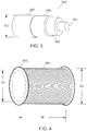
- the typical fiber optic cable 205 has a center single-mode optical fiber 301 encased in a plastic sheath 303 surrounded by a high strength jacket member 305 which can be made of a high strength composite fiber such as Kevlar.
- the high strength jacket member 305 can be surrounded by an abrasion resistant external coating or layer 307 which can be made of urethane or other similar materials.
- Such cables 205 are becoming standard with outside diameter (OD) that is approximately 2.9 mm. These cables 205 can be used with subsea remote vehicles where the high strength, toughness and abrasion resistance are needed to survive harsh environments.
- the present invention can use the smaller diameter fiber optic cable 205 that can be partially wound on a drum inside the ROV with the main cable 205 supply wound on a larger main supply drum aboard the surface support vessel.
- the small diameter armored fiber cables 205 can be used by ROVs 201 to dive to depths and ranges beyond the limits of prior ROVs which are limited by the hydrodynamic drag forces on the long length of thick cable containing electrical conductors.
- the length of cable 205 being dragged through the water is relatively short and the drag forces can be well below the maximum working tension.
- the depth that the ROV 201 is capable of reaching is limited by the ROV thrust 215 and its ability to drag cable 205 through the water.
- the underwater movement of the cable 205 is resisted by the fluid drag on the outer surfaces of the cable 205 which increases as more cable 205 is placed in the water from the main supply reel 231.
- Cable drag can include a combination of skin friction drag and form drag depending on how the cable 205 is being pulled. Skin friction drag arises from the friction of the water against the "skin" of the cable 205 that is moving through it.
- the thrust required to move the ROV can be reduced by lowering the cable drag.
- a first ROV having a first maximum thrust will have a first maximum depth and/or range that are proportional to the first maximum thrust.
- a second ROV which can have double the maximum thrust can overcome twice the amount of drag and therefore can have twice the maximum depth and/or range of the first ROV.
- the surface area and drag on the cable from the water can also be reduced by at least 50% or more.
- an ROV can significantly increase by more than double the maximum depth or range without increasing the thrust output of the ROV.
- This improved functional performance with reduced cable drag can provide a significant performance advantage for a an ROV having an internal battery which only requires a thin optical fiber cable compared to an ROV supplied with electrical power from a surface support vessel having a thicker cable.
- a small cable 205 may have a maximum safe working tension of about 22,68 kilograms (50 lbs) or less.
- the inventive system includes a cable storage device 553 on the ROV 201 which can be a drum or a spool aboard the 201 onto which a portion of the cable 205 is wound.
- the ROV cable storage device 553 is controlled so that it does not pay out under normal circumstances and the cable 205 remains locked within the ROV 201 until the cable 205 tension reaches or approaches its maximum allowed operating tension, which can be 22, 68 kilograms (50 lbs).
- the rate of cable release can be variable.
- the cable 205 can be released at 18,14 kilograms (40 lbs) at a slow rate and then released at a much faster rate as the tension increases so that the tension never reaches 22, 68 kilograms (50 lbs).
- the depth or range at which the surface supplied cable 205 reaches its maximum operational tensile limit will vary greatly depending on many factors including: the speed of the vehicle, the speed of water currents, the depth of the vehicle, etc.
- the cable tension can be greatest at its attachment to the ROV 201.
- the cable release mechanism can measure the cable tension at the vehicle end and that data can be relayed to the support vessel. As the cable tension approaches reaches a predetermined maximum allowable working tension, typically 22, 68 kilograms (50 lbs), the tether is released from the vehicle and the vehicle spool is paid out to relive tension and enable the vehicle to continue as needed deeper and/or further.
- the release of the cable by the cable release mechanism on the ROV 201 can be either an automated control mechanism or in response to a manually operated control signal from the support vessel.
- the ROV 201 can carry an onboard store of 304,8 meter (1,000 feet) of cable 205 that can enable the ROV 201 to continue 304,8 meter (1,000 ft) deeper and/or further than the limits of what could have otherwise been achieved without damaging the small diameter optical fiber.
- the cable release mechanism 551 includes a spool 553 storing a portion of the cable 205.
- the spool 553 can be aligned transversely with the ROV so that the center axis is perpendicular to the center line of the ROV.
- a locking block 555 that can be bonded to the cable 205 that engages locking arms 557.
- the locking block 555 can prevent the cable 205 from being removed from the spool 553 until a tension above a predetermined tension is detected by the cable release mechanism 551.
- the predetermined tension of the locking arms 557 can be equal to or less than the safe working tension of the cable 205.
- the locking block 555 can be released from the locking arms 557 and the spool 553 can rotate to release the cable 205.
- the spool 553 can be coupled to an optical slip ring 559 which allows the optical fiber 205 to rotate while transmitting signals to the ROV.
- locking arms 557 may be controlled by control signals from a support vessel.
- the spool 553 can also be coupled to a torque controller 561 which can apply rotational resistance to control the rotation of the spool 553 and the release rate of the cable 205 from the ROV.
- the torque controller 561 can be configured to apply a steady frictional resistance so that when the tension is below, the predetermined tension, the spool 553 rotation can be stopped or very slow. However, if the tension is significantly higher than the predetermined value, the rate of rotation can be increased proportionally to reduce the tension below the maximum working load.
- the cable release mechanism 551 can transmit signals to indicate that the predetermined tension has been exceeded and indicate the quantity of cable 205 remaining on the spool 553.
- the cable release mechanism 551 may be able to determine the length of cable 205 released by counting the number of rotations of the spool 553 when the cable 205 is released. As shown in the skin and form drag equations above, the cable drag is proportional to the cable 205 velocity through the water squared.
- an operator of the ROV 201 can transmit a signal from the support vessel to reduce the ROV 201 speed to reduce the tension in the cable 205. This slower speed can prevent the ROV 201 from running out of cable 205.
- the locking arms 557 can rotate about pivot points 563 and a torque can be applied to the locking arms 557 to hole the block 555 in place to prevent cable 205 from being released. If the cable tension force exceeds the force of the arms 557 against the block 555, the arms 557 will rotate and release the block 555 which will allow the cable 205 to be released from the ROV as described above.
- the arms 557 can be controlled manually by a controller on the support vessel. If the operator detects the tension in the cable above the maximum working load, a controller can transmit a signal to the ROV to release the locking arms 557. The manual control can be used together with the automatic cable release system.
- the spool 553 can be aligned with the center axis parallel to the center line of the ROV 201.
- the spool 553 can also be mounted in a manner that does not require the spool 553 to rotate.
- the cable 205 can be removed from one end of the spool 553 in a spiral manner without rotation.
- the spool 553 can be configured in a transverse manner or the cable 205 can be placed in any other suitable cable 205 storage device on the ROV. In this embodiment, the cable 205 is then wrapped several times around a capstan pulley 573.
- the pulley 573 can have a high friction surface such as a textured rubber outer surface so that the cable 205 does not slide over the surface of the pulley 573 when the cable 205 is tensioned.
- a strain monitoring device 577 can be coupled to the cable release mechanism 571 and measurement signals from the strain monitoring device 577 can be used to determine if the predetermined tension has been exceeded.
- the strain gauge instrument 577 can measure the strain on the holding block or capstan pulley 573.
- the strain gauge measures any deformation of the holding block or capstan pulley. Based upon the deformation, the pulling force of these components and the tension of the cable 205 can be calculated.
- the strain gauge 577 output can be transmitted to a control system on the cable release mechanism 571 and/or through the cable to the support vessel. If the tension exceeds the predetermined value which can be the maximum working tension or less, the cable release mechanism 571 can allow the pulley 575 to rotate and release the stored cable 205.
- the rate of release of the cable 205 can be controlled by a torque control device 571 which applies rotational friction to the rotation of the pulley 575.
- the strain gauge 577 output can be used to automatically release the cable 205.
- the cable tension information can be reviewed by an operator on the support vessel and the operator can send a cable release signal to the cable release mechanism 571.
- the manual control can also be used together with the automatic cable release mechanism 571.
- a hybrid cable 505 can include a first section having a first cable 205 which was described above with reference to FIG. 3 , that is coupled to a second cable 501 which can be the raw optical fiber having an outer diameter of about 0.254 mm.
- the first cable 205 can be fused or optically coupled at a connection point 507 to a second cable 501 which can be the raw optical fiber.
- Data transmitted between the ROV 201 and the support vessel 209 can be transmitted through both the first cable 205, the connection point 507 and the second cable 505.
- the armored fiber cable 205 can initially be attached to the ROV 201 and placed in the water at the support vessel 209 as the ROV 201 travels away from the support vessel 209.
- the ROV 201 can continue to store a long length of the thinner raw optical fiber cable 501 that is held in the ROV 201 until it needs to be released.
- the first cable 205 can be fully released and can extend down from the support vessel before the ROV 201 releases the second cable 501 and continues to dive. After the first cable 205 is completely released, the ROV can continue to travel away from the support vessel 209 by releasing the second cable 501.
- This hybrid cable 505 can allow the ROV to make very long and deep dives.
- the ROV may store a longer length of the second cable 501 than the length of the first optical cable 205. Once the dive is complete, the ROV and the first cable 205 can be recovered, while the second cable 501 can be broken in the water.
- Very longest and deep dives can be achieved by storing a very large quantity of raw, 0.01 inch diameter fiber aboard the vehicle and releasing that through a fiber management system.
- the first stage of the vehicle deployment can be achieved with the recoverable armored small diameter cable 205 until the limits of its deployment are reached and the rest of the vehicle mission uses disposable optical fiber. This is further described in U.S. patent application Ser. No. 12/795,971 , "Ocean Deployable Biodegradable Optical Fiber Cable".
- the second fiber cable 501 may only be released from the ROV 201 in the event of an emergency, such as if the armored cable 205 is caught and this threatens to trap the ROV 201.
- the multi mode fiber deployment system described in this invention can allow for simple surface cable to be used while retaining the increased depth and range advantages of vehicle stored cable payout.
Landscapes
- Engineering & Computer Science (AREA)
- Mechanical Engineering (AREA)
- Ocean & Marine Engineering (AREA)
- Chemical & Material Sciences (AREA)
- Analytical Chemistry (AREA)
- Physics & Mathematics (AREA)
- General Physics & Mathematics (AREA)
- Laying Of Electric Cables Or Lines Outside (AREA)
- Light Guides In General And Applications Therefor (AREA)
- Electric Cable Installation (AREA)
- Mechanical Coupling Of Light Guides (AREA)
Claims (14)
- Appareil de commande de tension de câble comprenant :un bac de surface (209) ;un véhicule sous-marin téléguidé (ROV) (201), le ROV (201) comprenant une bobine (553) et un mécanisme de commande de tension de câble (221) avec un capteur de tension ;un câble (205) qui inclut une fibre optique adaptée pour transmettre des signaux entre une commande (558) sur le bac de surface (209) et le ROV (201) ;un dispositif de stockage de câble (211) couplé au bac de surface (209) pour stocker une première partie du câble (205) ;dans lequel la bobine (553) est configurée pour stocker une deuxième partie du câble (205) ;un mécanisme de libération (551) qui commande le retrait de la deuxième partie du câble (205) d'avec la bobine (553) ; etdans lequel le capteur de tension est configuré pour détecter la tension dans la deuxième partie du câble (205) ;dans lequel le mécanisme de libération (551) est configuré pour libérer la deuxième partie du câble (205) de la bobine (553) lorsque le câble de tension (561) détecte que la tension dans le câble (205) est supérieure à une valeur prédéterminée.
- Appareil selon la revendication 1, dans lequel la valeur prédéterminée est supérieure à 22,7 kg (50 livres) de tension.
- Appareil selon la revendication 1, dans lequel le mécanisme de libération (551) inclut un bloc (555) relié à la deuxième partie du câble (205) et des verrous mécaniques (557) qui empêchent le bloc (555) de se déplacer jusqu'à ce que la tension dans le câble (205) soit supérieure à la valeur prédéterminée.
- Appareil selon la revendication 1 comprenant en outre : une bague collectrice optique (559); dans lequel les données sont transmises par le biais de la bague collectrice optique (559).
- Appareil selon la revendication 1, dans lequel le mécanisme de libération (551) inclut une commande de vitesse pour commander la vitesse à laquelle la deuxième partie du câble (205) est retirée de la bobine (553) lorsque la tension dans le câble (205) dépasse la valeur prédéterminée.
- Appareil selon la revendication 5, dans lequel la vitesse à laquelle la deuxième partie du câble (205) est retirée de la bobine (553) est proportionnelle à la tension du câble (205) au-dessus de la valeur prédéterminée.
- Appareil selon la revendication 5, dans lequel la commande de vitesse de retrait inclut une commande de couple (561) qui commande le frottement de rotation de la bobine (553).
- Appareil selon la revendication 1, dans lequel le mécanisme de libération (551) inclut une poulie et le câble (205) est enroulé deux ou plusieurs fois autour de la poulie.
- Appareil selon la revendication 8, dans lequel la poulie est verrouillée lorsque la tension dans le câble (205) est inférieure à la valeur prédéterminée.
- Appareil selon la revendication 8, dans lequel la poulie est couplée à une commande de couple (561) pour commander le frottement de rotation de la poulie.
- Appareil selon la revendication 1, dans lequel le mécanisme de libération (551) inclut une commande de vitesse pour commander la vitesse à laquelle la deuxième partie du câble (205) est retirée du dispositif de stockage lorsque la tension dans le câble (205) dépasse la valeur prédéterminée.
- Appareil selon la revendication 11, dans lequel la vitesse à laquelle la deuxième partie du câble (205) est retirée du dispositif de stockage est proportionnelle à la tension du câble (205) au-dessus de la valeur prédéterminée.
- Appareil selon la revendication 12, dans lequel la commande de vitesse de retrait inclut une commande de couple (561) qui commande la vitesse de retrait du dispositif de stockage.
- Appareil selon la revendication 1, dans lequel le câble (205) est libéré du dispositif de stockage (211) lorsque le ROV (201) s'éloigne du bac de surface (209).
Applications Claiming Priority (2)
| Application Number | Priority Date | Filing Date | Title |
|---|---|---|---|
| US201161500246P | 2011-06-23 | 2011-06-23 | |
| PCT/US2012/043460 WO2012177824A1 (fr) | 2011-06-23 | 2012-06-21 | Système de câble à fibres optiques double mode pour véhicule actionné à distance sous l'eau |
Publications (2)
| Publication Number | Publication Date |
|---|---|
| EP2723634A1 EP2723634A1 (fr) | 2014-04-30 |
| EP2723634B1 true EP2723634B1 (fr) | 2019-01-09 |
Family
ID=46489473
Family Applications (1)
| Application Number | Title | Priority Date | Filing Date |
|---|---|---|---|
| EP12733558.6A Not-in-force EP2723634B1 (fr) | 2011-06-23 | 2012-06-21 | Système de câble à fibres optiques double mode pour véhicule actionné à distance sous l'eau |
Country Status (4)
| Country | Link |
|---|---|
| US (1) | US8770129B2 (fr) |
| EP (1) | EP2723634B1 (fr) |
| JP (1) | JP6271420B2 (fr) |
| WO (1) | WO2012177824A1 (fr) |
Families Citing this family (22)
| Publication number | Priority date | Publication date | Assignee | Title |
|---|---|---|---|---|
| JP6216315B2 (ja) | 2011-07-28 | 2017-10-18 | ブルーフィン・ロボティクス・コーポレーション | 水中遠隔操縦ビークル用小径テザーの自己放出および巻取りのための内部ウインチ |
| GB2523600B (en) * | 2014-03-01 | 2016-07-06 | Seadrift Holdings Ltd | Connecting an underwater vehicle to a tether |
| DE102014110604A1 (de) * | 2014-07-28 | 2016-01-28 | Atlas Elektronik Gmbh | Attrappe, Attrappensystem, Unterwasserfahrzeug oder Absenker sowie Verbringvorrichtung, Fahrzeug und Trainingsverfahren |
| CN105159320A (zh) * | 2014-08-12 | 2015-12-16 | 天津北洋蓝水科技有限公司 | 适用于复杂水域的水下目标探测平台系统及其使用方法 |
| CN104296915B (zh) * | 2014-10-20 | 2016-02-17 | 上海交通大学 | 用于水下脐带缆张力监控的装置及方法 |
| JP6409602B2 (ja) | 2015-02-06 | 2018-10-24 | ブラザー工業株式会社 | 画像形成装置および移動部材 |
| US9958544B2 (en) * | 2015-03-18 | 2018-05-01 | The United States Of America, As Represented By The Secretary Of The Navy | Vessel-towed multiple sensor systems and related methods |
| US10024459B1 (en) * | 2015-04-02 | 2018-07-17 | Ag Leader Technology, Inc. | Tile feed wheel control |
| CN108792838B (zh) * | 2017-05-05 | 2020-10-30 | 北京臻迪科技股份有限公司 | 一种涉水机器人的线缆控制系统及线缆控制方法 |
| JP6716498B2 (ja) * | 2017-06-22 | 2020-07-01 | 株式会社FullDepth | アダプタ、電子機器及び電子機器を搬送する方法 |
| US10813281B2 (en) | 2018-02-20 | 2020-10-27 | Ag Leader Technology | Apparatus, systems and methods for applying fluid |
| FR3088731B1 (fr) * | 2018-11-15 | 2022-01-21 | Thales Sa | Multiplexeur de signaux pour sonar |
| CN109808857B (zh) * | 2019-03-28 | 2021-10-01 | 王馨悦 | 一种海上移动潜水装置 |
| CN110816751A (zh) * | 2019-12-05 | 2020-02-21 | 交通运输部天津水运工程科学研究所 | 一种船舶缆绳破断保护装置及安装方法 |
| KR102121950B1 (ko) * | 2020-01-23 | 2020-06-11 | 권오봉 | 케이블 텐션유지가 가능한 수중드론세트 |
| CN111208269A (zh) * | 2020-03-04 | 2020-05-29 | 中国海洋大学 | 一种低成本近海养殖水质监测系统及方法 |
| CN111942530A (zh) * | 2020-08-24 | 2020-11-17 | 上海海洋大学 | 一种连接水下机器人的无人船装置 |
| US11958580B2 (en) | 2020-11-12 | 2024-04-16 | Eagle Technology, Llc | Unmanned underwater vehicle (UUV) based underwater communications network including short-range navigation device and related methods |
| US11438072B2 (en) | 2020-11-12 | 2022-09-06 | Eagle Technology, Llc | Docking system including first and second optical transceivers for docking and related methods |
| CN113636045A (zh) * | 2021-07-15 | 2021-11-12 | 中国水产科学研究院渔业机械仪器研究所 | 一种适用于池壁作业的水下机器人定位装置及方法 |
| US11365101B1 (en) * | 2021-07-29 | 2022-06-21 | Altec Industries, Inc. | Aided freewheel winch assembly |
| CN117342349B (zh) * | 2023-11-16 | 2025-11-18 | 宁波东方电缆股份有限公司 | 一种缆线输送设计分析方法 |
Family Cites Families (13)
| Publication number | Priority date | Publication date | Assignee | Title |
|---|---|---|---|---|
| US4010619A (en) * | 1976-05-24 | 1977-03-08 | The United States Of America As Represented By The Secretary Of The Navy | Remote unmanned work system (RUWS) electromechanical cable system |
| US4458880A (en) * | 1982-02-05 | 1984-07-10 | Conti Allen C | Method and apparatus to measure tension in a pull line for cable |
| JPS62265095A (ja) * | 1986-05-13 | 1987-11-17 | Toshiba Corp | 無人潜水艇 |
| US5551545A (en) * | 1994-03-18 | 1996-09-03 | Gelfman; Stanley | Automatic deployment and retrieval tethering system |
| JPH082821A (ja) * | 1994-06-16 | 1996-01-09 | Nippon Steel Corp | 高張力解舒装置 |
| JP3743529B2 (ja) * | 1995-09-25 | 2006-02-08 | 住友電気工業株式会社 | 無人潜水機システム |
| US7331436B1 (en) * | 2003-03-26 | 2008-02-19 | Irobot Corporation | Communications spooler for a mobile robot |
| US7252046B1 (en) * | 2003-12-08 | 2007-08-07 | The United States Of America As Represented By The Secretary Of The Navy | Apparatus for deploying and recovering a towed acoustic line array from an unmanned undersea vehicle |
| JP2009051470A (ja) * | 2007-08-29 | 2009-03-12 | Robot Technos:Kk | 水中航走体遠隔操作システム及び同システムの光ケーブルのドラム巻装面調整装置 |
| KR101622306B1 (ko) | 2009-10-29 | 2016-05-19 | 삼성전자주식회사 | 그라펜 시트, 이를 포함하는 그라펜 기재 및 그의 제조방법 |
| US7775174B1 (en) * | 2008-08-29 | 2010-08-17 | Vehicle Control Technologies, Inc. | Self-propelled tow body |
| US20100050918A1 (en) * | 2008-09-04 | 2010-03-04 | Richard Burbank Provonchee | Anchor Retrieval System (ARS) |
| DE102009053742B4 (de) * | 2009-11-18 | 2012-01-26 | Atlas Elektronik Gmbh | Unbemanntes Unterwasserfahrzeug und Einrichtung zum Anschluss eines Lichtwellenleiterkabels an ein unbemanntes Unterwasserfahrzeug |
-
2012
- 2012-06-21 JP JP2014517139A patent/JP6271420B2/ja not_active Expired - Fee Related
- 2012-06-21 EP EP12733558.6A patent/EP2723634B1/fr not_active Not-in-force
- 2012-06-21 WO PCT/US2012/043460 patent/WO2012177824A1/fr not_active Ceased
- 2012-06-22 US US13/531,112 patent/US8770129B2/en active Active
Non-Patent Citations (1)
| Title |
|---|
| None * |
Also Published As
| Publication number | Publication date |
|---|---|
| JP2014526991A (ja) | 2014-10-09 |
| WO2012177824A1 (fr) | 2012-12-27 |
| JP6271420B2 (ja) | 2018-01-31 |
| US20120328372A1 (en) | 2012-12-27 |
| US8770129B2 (en) | 2014-07-08 |
| EP2723634A1 (fr) | 2014-04-30 |
Similar Documents
| Publication | Publication Date | Title |
|---|---|---|
| EP2723634B1 (fr) | Système de câble à fibres optiques double mode pour véhicule actionné à distance sous l'eau | |
| US10508000B2 (en) | Internal winch for self payout and re-wind of a small diameter tether for underwater remotely operated vehicle | |
| US7621229B2 (en) | Systems and methods for tethering underwater vehicles | |
| EP0907087B1 (fr) | Configuration de cable sous-marin | |
| US9463849B2 (en) | Mechanical tether system for a submersible vehicle | |
| CA2635911C (fr) | Dispositions de cable sous-marin et dispositions de support de bobine pour un cable sous-marin | |
| CA2232570C (fr) | Ensembles et dispositifs pour cable sous-marin | |
| US9099851B2 (en) | Rotary joint/swivel device | |
| WO2018160220A1 (fr) | Terminaison intelligente de corde ou de câble | |
| US8989656B2 (en) | Anchor data communication system | |
| WO1997011395A9 (fr) | Dispositif de support de bobine pour un cable sous-marin | |
| EP2621796B1 (fr) | Systeme comprenant un engin sous-marin et une base situee en surface. | |
| Aoki et al. | Development of deep sea free swimming ROV" UROV7K" | |
| US7913944B1 (en) | Cable brake for sea deployments of light cable | |
| CN109516320B (zh) | 一种适用于变直径线缆自动收排放的控制方法 | |
| Fletcher | Curly Wurly Concept Analysis. Phase I | |
| CN210212725U (zh) | 子母rov系统 | |
| EP1416299A2 (fr) | Dispositif de support de bobine pour un câble sous-marin | |
| Fletcher | Curly Wurly Concept Analysis Phase I Report | |
| EP1102090A2 (fr) | Appareil pour le contrôle de la position d'un cable sous-marin | |
| Nandagopan et al. | Advances in winch system for defence applications | |
| BR112022007381B1 (pt) | Módulo inteligente para fixação a um membro de resistência de fibra |
Legal Events
| Date | Code | Title | Description |
|---|---|---|---|
| PUAI | Public reference made under article 153(3) epc to a published international application that has entered the european phase |
Free format text: ORIGINAL CODE: 0009012 |
|
| 17P | Request for examination filed |
Effective date: 20131219 |
|
| AK | Designated contracting states |
Kind code of ref document: A1 Designated state(s): AL AT BE BG CH CY CZ DE DK EE ES FI FR GB GR HR HU IE IS IT LI LT LU LV MC MK MT NL NO PL PT RO RS SE SI SK SM TR |
|
| DAX | Request for extension of the european patent (deleted) | ||
| STAA | Information on the status of an ep patent application or granted ep patent |
Free format text: STATUS: EXAMINATION IS IN PROGRESS |
|
| 17Q | First examination report despatched |
Effective date: 20170404 |
|
| GRAP | Despatch of communication of intention to grant a patent |
Free format text: ORIGINAL CODE: EPIDOSNIGR1 |
|
| STAA | Information on the status of an ep patent application or granted ep patent |
Free format text: STATUS: GRANT OF PATENT IS INTENDED |
|
| INTG | Intention to grant announced |
Effective date: 20180802 |
|
| GRAS | Grant fee paid |
Free format text: ORIGINAL CODE: EPIDOSNIGR3 |
|
| GRAA | (expected) grant |
Free format text: ORIGINAL CODE: 0009210 |
|
| STAA | Information on the status of an ep patent application or granted ep patent |
Free format text: STATUS: THE PATENT HAS BEEN GRANTED |
|
| AK | Designated contracting states |
Kind code of ref document: B1 Designated state(s): AL AT BE BG CH CY CZ DE DK EE ES FI FR GB GR HR HU IE IS IT LI LT LU LV MC MK MT NL NO PL PT RO RS SE SI SK SM TR |
|
| REG | Reference to a national code |
Ref country code: GB Ref legal event code: FG4D |
|
| REG | Reference to a national code |
Ref country code: CH Ref legal event code: EP Ref country code: AT Ref legal event code: REF Ref document number: 1086959 Country of ref document: AT Kind code of ref document: T Effective date: 20190115 |
|
| REG | Reference to a national code |
Ref country code: IE Ref legal event code: FG4D |
|
| REG | Reference to a national code |
Ref country code: DE Ref legal event code: R096 Ref document number: 602012055695 Country of ref document: DE |
|
| REG | Reference to a national code |
Ref country code: NL Ref legal event code: MP Effective date: 20190109 |
|
| REG | Reference to a national code |
Ref country code: LT Ref legal event code: MG4D |
|
| REG | Reference to a national code |
Ref country code: NO Ref legal event code: T2 Effective date: 20190109 |
|
| PG25 | Lapsed in a contracting state [announced via postgrant information from national office to epo] |
Ref country code: NL Free format text: LAPSE BECAUSE OF FAILURE TO SUBMIT A TRANSLATION OF THE DESCRIPTION OR TO PAY THE FEE WITHIN THE PRESCRIBED TIME-LIMIT Effective date: 20190109 |
|
| REG | Reference to a national code |
Ref country code: AT Ref legal event code: MK05 Ref document number: 1086959 Country of ref document: AT Kind code of ref document: T Effective date: 20190109 |
|
| PG25 | Lapsed in a contracting state [announced via postgrant information from national office to epo] |
Ref country code: FI Free format text: LAPSE BECAUSE OF FAILURE TO SUBMIT A TRANSLATION OF THE DESCRIPTION OR TO PAY THE FEE WITHIN THE PRESCRIBED TIME-LIMIT Effective date: 20190109 Ref country code: ES Free format text: LAPSE BECAUSE OF FAILURE TO SUBMIT A TRANSLATION OF THE DESCRIPTION OR TO PAY THE FEE WITHIN THE PRESCRIBED TIME-LIMIT Effective date: 20190109 Ref country code: PT Free format text: LAPSE BECAUSE OF FAILURE TO SUBMIT A TRANSLATION OF THE DESCRIPTION OR TO PAY THE FEE WITHIN THE PRESCRIBED TIME-LIMIT Effective date: 20190509 Ref country code: SE Free format text: LAPSE BECAUSE OF FAILURE TO SUBMIT A TRANSLATION OF THE DESCRIPTION OR TO PAY THE FEE WITHIN THE PRESCRIBED TIME-LIMIT Effective date: 20190109 Ref country code: LT Free format text: LAPSE BECAUSE OF FAILURE TO SUBMIT A TRANSLATION OF THE DESCRIPTION OR TO PAY THE FEE WITHIN THE PRESCRIBED TIME-LIMIT Effective date: 20190109 Ref country code: PL Free format text: LAPSE BECAUSE OF FAILURE TO SUBMIT A TRANSLATION OF THE DESCRIPTION OR TO PAY THE FEE WITHIN THE PRESCRIBED TIME-LIMIT Effective date: 20190109 |
|
| PG25 | Lapsed in a contracting state [announced via postgrant information from national office to epo] |
Ref country code: LV Free format text: LAPSE BECAUSE OF FAILURE TO SUBMIT A TRANSLATION OF THE DESCRIPTION OR TO PAY THE FEE WITHIN THE PRESCRIBED TIME-LIMIT Effective date: 20190109 Ref country code: RS Free format text: LAPSE BECAUSE OF FAILURE TO SUBMIT A TRANSLATION OF THE DESCRIPTION OR TO PAY THE FEE WITHIN THE PRESCRIBED TIME-LIMIT Effective date: 20190109 Ref country code: HR Free format text: LAPSE BECAUSE OF FAILURE TO SUBMIT A TRANSLATION OF THE DESCRIPTION OR TO PAY THE FEE WITHIN THE PRESCRIBED TIME-LIMIT Effective date: 20190109 Ref country code: IS Free format text: LAPSE BECAUSE OF FAILURE TO SUBMIT A TRANSLATION OF THE DESCRIPTION OR TO PAY THE FEE WITHIN THE PRESCRIBED TIME-LIMIT Effective date: 20190509 Ref country code: BG Free format text: LAPSE BECAUSE OF FAILURE TO SUBMIT A TRANSLATION OF THE DESCRIPTION OR TO PAY THE FEE WITHIN THE PRESCRIBED TIME-LIMIT Effective date: 20190409 Ref country code: GR Free format text: LAPSE BECAUSE OF FAILURE TO SUBMIT A TRANSLATION OF THE DESCRIPTION OR TO PAY THE FEE WITHIN THE PRESCRIBED TIME-LIMIT Effective date: 20190410 |
|
| REG | Reference to a national code |
Ref country code: DE Ref legal event code: R097 Ref document number: 602012055695 Country of ref document: DE |
|
| PG25 | Lapsed in a contracting state [announced via postgrant information from national office to epo] |
Ref country code: DK Free format text: LAPSE BECAUSE OF FAILURE TO SUBMIT A TRANSLATION OF THE DESCRIPTION OR TO PAY THE FEE WITHIN THE PRESCRIBED TIME-LIMIT Effective date: 20190109 Ref country code: EE Free format text: LAPSE BECAUSE OF FAILURE TO SUBMIT A TRANSLATION OF THE DESCRIPTION OR TO PAY THE FEE WITHIN THE PRESCRIBED TIME-LIMIT Effective date: 20190109 Ref country code: AT Free format text: LAPSE BECAUSE OF FAILURE TO SUBMIT A TRANSLATION OF THE DESCRIPTION OR TO PAY THE FEE WITHIN THE PRESCRIBED TIME-LIMIT Effective date: 20190109 Ref country code: RO Free format text: LAPSE BECAUSE OF FAILURE TO SUBMIT A TRANSLATION OF THE DESCRIPTION OR TO PAY THE FEE WITHIN THE PRESCRIBED TIME-LIMIT Effective date: 20190109 Ref country code: CZ Free format text: LAPSE BECAUSE OF FAILURE TO SUBMIT A TRANSLATION OF THE DESCRIPTION OR TO PAY THE FEE WITHIN THE PRESCRIBED TIME-LIMIT Effective date: 20190109 Ref country code: IT Free format text: LAPSE BECAUSE OF FAILURE TO SUBMIT A TRANSLATION OF THE DESCRIPTION OR TO PAY THE FEE WITHIN THE PRESCRIBED TIME-LIMIT Effective date: 20190109 Ref country code: SK Free format text: LAPSE BECAUSE OF FAILURE TO SUBMIT A TRANSLATION OF THE DESCRIPTION OR TO PAY THE FEE WITHIN THE PRESCRIBED TIME-LIMIT Effective date: 20190109 Ref country code: AL Free format text: LAPSE BECAUSE OF FAILURE TO SUBMIT A TRANSLATION OF THE DESCRIPTION OR TO PAY THE FEE WITHIN THE PRESCRIBED TIME-LIMIT Effective date: 20190109 |
|
| PLBE | No opposition filed within time limit |
Free format text: ORIGINAL CODE: 0009261 |
|
| STAA | Information on the status of an ep patent application or granted ep patent |
Free format text: STATUS: NO OPPOSITION FILED WITHIN TIME LIMIT |
|
| PG25 | Lapsed in a contracting state [announced via postgrant information from national office to epo] |
Ref country code: SM Free format text: LAPSE BECAUSE OF FAILURE TO SUBMIT A TRANSLATION OF THE DESCRIPTION OR TO PAY THE FEE WITHIN THE PRESCRIBED TIME-LIMIT Effective date: 20190109 |
|
| 26N | No opposition filed |
Effective date: 20191010 |
|
| PG25 | Lapsed in a contracting state [announced via postgrant information from national office to epo] |
Ref country code: MC Free format text: LAPSE BECAUSE OF FAILURE TO SUBMIT A TRANSLATION OF THE DESCRIPTION OR TO PAY THE FEE WITHIN THE PRESCRIBED TIME-LIMIT Effective date: 20190109 |
|
| REG | Reference to a national code |
Ref country code: CH Ref legal event code: PL |
|
| GBPC | Gb: european patent ceased through non-payment of renewal fee |
Effective date: 20190621 |
|
| PG25 | Lapsed in a contracting state [announced via postgrant information from national office to epo] |
Ref country code: SI Free format text: LAPSE BECAUSE OF FAILURE TO SUBMIT A TRANSLATION OF THE DESCRIPTION OR TO PAY THE FEE WITHIN THE PRESCRIBED TIME-LIMIT Effective date: 20190109 |
|
| REG | Reference to a national code |
Ref country code: BE Ref legal event code: MM Effective date: 20190630 |
|
| PG25 | Lapsed in a contracting state [announced via postgrant information from national office to epo] |
Ref country code: TR Free format text: LAPSE BECAUSE OF FAILURE TO SUBMIT A TRANSLATION OF THE DESCRIPTION OR TO PAY THE FEE WITHIN THE PRESCRIBED TIME-LIMIT Effective date: 20190109 |
|
| PG25 | Lapsed in a contracting state [announced via postgrant information from national office to epo] |
Ref country code: GB Free format text: LAPSE BECAUSE OF NON-PAYMENT OF DUE FEES Effective date: 20190621 Ref country code: IE Free format text: LAPSE BECAUSE OF NON-PAYMENT OF DUE FEES Effective date: 20190621 |
|
| PG25 | Lapsed in a contracting state [announced via postgrant information from national office to epo] |
Ref country code: BE Free format text: LAPSE BECAUSE OF NON-PAYMENT OF DUE FEES Effective date: 20190630 Ref country code: LU Free format text: LAPSE BECAUSE OF NON-PAYMENT OF DUE FEES Effective date: 20190621 Ref country code: LI Free format text: LAPSE BECAUSE OF NON-PAYMENT OF DUE FEES Effective date: 20190630 Ref country code: CH Free format text: LAPSE BECAUSE OF NON-PAYMENT OF DUE FEES Effective date: 20190630 |
|
| PG25 | Lapsed in a contracting state [announced via postgrant information from national office to epo] |
Ref country code: CY Free format text: LAPSE BECAUSE OF FAILURE TO SUBMIT A TRANSLATION OF THE DESCRIPTION OR TO PAY THE FEE WITHIN THE PRESCRIBED TIME-LIMIT Effective date: 20190109 |
|
| PG25 | Lapsed in a contracting state [announced via postgrant information from national office to epo] |
Ref country code: MT Free format text: LAPSE BECAUSE OF FAILURE TO SUBMIT A TRANSLATION OF THE DESCRIPTION OR TO PAY THE FEE WITHIN THE PRESCRIBED TIME-LIMIT Effective date: 20190109 Ref country code: HU Free format text: LAPSE BECAUSE OF FAILURE TO SUBMIT A TRANSLATION OF THE DESCRIPTION OR TO PAY THE FEE WITHIN THE PRESCRIBED TIME-LIMIT; INVALID AB INITIO Effective date: 20120621 |
|
| PG25 | Lapsed in a contracting state [announced via postgrant information from national office to epo] |
Ref country code: MK Free format text: LAPSE BECAUSE OF FAILURE TO SUBMIT A TRANSLATION OF THE DESCRIPTION OR TO PAY THE FEE WITHIN THE PRESCRIBED TIME-LIMIT Effective date: 20190109 |
|
| P01 | Opt-out of the competence of the unified patent court (upc) registered |
Effective date: 20230519 |
|
| PGFP | Annual fee paid to national office [announced via postgrant information from national office to epo] |
Ref country code: NO Payment date: 20230628 Year of fee payment: 12 Ref country code: FR Payment date: 20230626 Year of fee payment: 12 Ref country code: DE Payment date: 20230626 Year of fee payment: 12 |
|
| REG | Reference to a national code |
Ref country code: DE Ref legal event code: R119 Ref document number: 602012055695 Country of ref document: DE |
|
| PG25 | Lapsed in a contracting state [announced via postgrant information from national office to epo] |
Ref country code: DE Free format text: LAPSE BECAUSE OF NON-PAYMENT OF DUE FEES Effective date: 20250101 |
|
| PG25 | Lapsed in a contracting state [announced via postgrant information from national office to epo] |
Ref country code: NO Free format text: LAPSE BECAUSE OF NON-PAYMENT OF DUE FEES Effective date: 20240630 |
|
| PG25 | Lapsed in a contracting state [announced via postgrant information from national office to epo] |
Ref country code: FR Free format text: LAPSE BECAUSE OF NON-PAYMENT OF DUE FEES Effective date: 20240630 |