EP2723976B1 - Barrière annulaire avec joint externe - Google Patents
Barrière annulaire avec joint externe Download PDFInfo
- Publication number
- EP2723976B1 EP2723976B1 EP12732597.5A EP12732597A EP2723976B1 EP 2723976 B1 EP2723976 B1 EP 2723976B1 EP 12732597 A EP12732597 A EP 12732597A EP 2723976 B1 EP2723976 B1 EP 2723976B1
- Authority
- EP
- European Patent Office
- Prior art keywords
- sleeve
- annular barrier
- safety
- expandable
- expandable sleeve
- Prior art date
- Legal status (The legal status is an assumption and is not a legal conclusion. Google has not performed a legal analysis and makes no representation as to the accuracy of the status listed.)
- Active
Links
Images


Classifications
-
- E—FIXED CONSTRUCTIONS
- E21—EARTH OR ROCK DRILLING; MINING
- E21B—EARTH OR ROCK DRILLING; OBTAINING OIL, GAS, WATER, SOLUBLE OR MELTABLE MATERIALS OR A SLURRY OF MINERALS FROM WELLS
- E21B33/00—Sealing or packing boreholes or wells
- E21B33/10—Sealing or packing boreholes or wells in the borehole
- E21B33/12—Packers; Plugs
- E21B33/127—Packers; Plugs with inflatable sleeve
-
- E—FIXED CONSTRUCTIONS
- E21—EARTH OR ROCK DRILLING; MINING
- E21B—EARTH OR ROCK DRILLING; OBTAINING OIL, GAS, WATER, SOLUBLE OR MELTABLE MATERIALS OR A SLURRY OF MINERALS FROM WELLS
- E21B33/00—Sealing or packing boreholes or wells
- E21B33/10—Sealing or packing boreholes or wells in the borehole
- E21B33/12—Packers; Plugs
-
- E—FIXED CONSTRUCTIONS
- E21—EARTH OR ROCK DRILLING; MINING
- E21B—EARTH OR ROCK DRILLING; OBTAINING OIL, GAS, WATER, SOLUBLE OR MELTABLE MATERIALS OR A SLURRY OF MINERALS FROM WELLS
- E21B33/00—Sealing or packing boreholes or wells
- E21B33/10—Sealing or packing boreholes or wells in the borehole
- E21B33/12—Packers; Plugs
- E21B33/1208—Packers; Plugs characterised by the construction of the sealing or packing means
-
- E—FIXED CONSTRUCTIONS
- E21—EARTH OR ROCK DRILLING; MINING
- E21B—EARTH OR ROCK DRILLING; OBTAINING OIL, GAS, WATER, SOLUBLE OR MELTABLE MATERIALS OR A SLURRY OF MINERALS FROM WELLS
- E21B43/00—Methods or apparatus for obtaining oil, gas, water, soluble or meltable materials or a slurry of minerals from wells
- E21B43/02—Subsoil filtering
- E21B43/10—Setting of casings, screens, liners or the like in wells
- E21B43/103—Setting of casings, screens, liners or the like in wells of expandable casings, screens, liners, or the like
Definitions
- the present invention relates to an annular barrier to be expanded in an annulus which comprises well fluid and is arranged between a well tubular structure and an inside wall of a borehole downhole, the annular barrier comprising a tubular part for mounting as part of the well tubular structure, the tubular part having a longitudinal axis, an expandable sleeve surrounding the tubular part and having an outer face, each end of the expandable sleeve being fastened to the tubular part by means of a connection part, an aperture in the tubular part or the connection part.
- Annular barriers are used in wellbores for different purposes, such as for providing a barrier for flowing between an inner and an outer tubular structure or an inner tubular structure and an inner wall of the borehole.
- the annular barriers are mounted as part of the well tubular structure.
- An annular barrier has an inner wall surrounded by an annular expandable sleeve.
- the expandable sleeve is typically made of an elastomeric material, but may also be made of metal. The sleeve is fastened at its ends to the inner wall of the annular barrier.
- a second annular barrier is used to seal off a zone between an inner and an outer tubular structure or a well tubular structure and the borehole.
- the first annular barrier is expanded on one side of the zone to be sealed off, and the second annular barrier is expanded on the other side of that zone. Thus, the entire zone is sealed off.
- the pressure envelope of a well is governed by the burst rating of the tubular and the well hardware etc. used within the well construction.
- the expandable sleeve of an annular barrier may be expanded by increasing the pressure within the well, which is the most cost-efficient way of expanding the sleeve.
- the burst rating of a well defines the maximum pressure that can be applied to the well for expansion of the sleeve, and it is desirable to minimise the expansion pressure required for expanding the sleeve to minimise the exposure of the well to the expansion pressure.
- annular barriers When expanded, annular barriers may be subjected to a continuous differential pressure or a periodically high pressure within the annulus.
- One of the purposes of the barrier is to contain this differential pressure and prevent a leak across the barrier.
- US 2006/027371 discloses an apparatus for preventing such leaks.
- the ability to seal against the differential pressure within the annulus by the expanded sleeve in certain well environments is insufficient for some well applications.
- the ability to seal may be improved by increasing the wall thickness or the strength of the material or by changing the type of external elastomers mounted on the expansion sleeve. However, this would increase the expansion pressure, which is not desirable, as already mentioned.
- annular barrier to be expanded in an annulus which comprises well fluid and is arranged between a well tubular structure and an inside wall of a borehole downhole, the annular barrier comprising:
- the annulus which is in fluid communication with the space may extend away from the safety sleeve.
- the safety sleeve may have an extension along the longitudinal axis of the tubular part which is less than 30% of an extension of the expandable sleeve along the longitudinal axis of the tubular part, preferably less than 20% of the extension of the expandable sleeve, more preferably less than 10% of the extension of the expandable sleeve.
- the safety sleeve may have an axial length along the longitudinal axis of the tubular part which is less than 50% of a length of the expandable sleeve along the longitudinal axis of the tubular part, the axial length along the longitudinal axis of the tubular part being less than 30% of the length of the expandable sleeve, preferably less than 20% of the length of the expandable sleeve and more preferably less than 15% of the length of the expandable sleeve along the longitudinal axis of the tubular part.
- the annular barrier may comprise a plurality of safety sleeves.
- the safety sleeve may comprise a sleeve part fastened to the expandable sleeve by means of at least one of the second connections and may have a thickness which is less than a thickness of the expandable sleeve.
- the safety sleeve may be shaped as a ring and be fastened to each connection along its entire circumference.
- the safety sleeve may be made of metal or polymers, such as an elastomeric material, silicone, or natural or syntactic rubber.
- the safety sleeve may be made of a material having a lower E-modulus than that of the expandable sleeve.
- the safety sleeve may comprise a recess.
- a sealing element may be arranged in the recess.
- the opening may be arranged between one of the connections and the recess.
- the opening may be arranged between one of the connections and the expandable sleeve.
- the opening may be provided as a groove in the one of the connections along the longitudinal axis of the tubular part.
- the safety sleeve may comprise a sleeve part fastened to the expandable sleeve by means of at least one of the connections, and the opening may be arranged between one of the connections and the sleeve part.
- the safety sleeve may comprise a sleeve part fastened to the expandable sleeve by means of at least one of the connections and a sheet arranged between the sleeve part and the expandable sleeve and at least partly surrounding the expandable sleeve.
- the sheet may extend further along the expandable sleeve between one of the connections and the expandable sleeve.
- the sheet may partly surround the expandable sleeve, providing a channel being the opening between the connection and the expandable sleeve.
- the safety sleeve may be connected to the expandable sleeve at a distance from the recess.
- a distance piece may be arranged in the space at the opening of the safety sleeve.
- a one-way valve may be arranged in the opening.
- the recess in a cross-section along the longitudinal axis of the tubular part, may have a square shape, a triangular shape or a trapezoidal shape.
- the sealing element may have a cross-sectional shape corresponding to the cross-sectional shape of the recess.
- the sealing element may, in a cross-section along the longitudinal axis of the tubular part, have a square shape, a triangular shape or a trapezoidal shape.
- first and second connections may be connection rings.
- connection rings may be welded, glued, bolted or riveted to the outer face of the expandable sleeve.
- the annular barrier may comprise a plurality of connection rings and a plurality of safety sleeves arranged between the connection rings.
- the annular barrier may have a first end and a second end, and the opening in a first safety sleeve positioned closest to the first end may be arranged closer to the first end than the second end in relation to a middle part of the first safety sleeve, and the opening in a second safety sleeve positioned closest to the second end may be arranged closer to the second end than the first end in relation to a middle part of the second safety sleeve.
- connections may comprise projection elements for anchoring the annular barrier along the longitudinal axis.
- the annular barrier may further comprise an anchoring section comprising projection elements arranged on the outer face of the expandable sleeve.
- the projection element may be a spike, barb or similar projection, or a circumferential peaking projection.
- the sealing element may extend radially beyond the rings from the expandable sleeve.
- the expandable sleeve may be capable of expanding to a diameter which is at least 10% larger, preferably at least 15% larger, more preferably at least 30% larger than that of an unexpanded sleeve.
- the expandable sleeve may have a wall thickness which is thinner than a length of the expandable sleeve, the thickness preferably being less than 25% of its length, more preferably less than 15% of its length, and even more preferably less than 10% of its length.
- the expandable sleeve may have a varying thickness along the periphery and/or length.
- connection parts may be slidable in relation to the tubular part of the annular barrier.
- At least one sealing element such as an O-ring, may be arranged between the slidable connection part and the tubular part.
- connection parts may be fixedly fastened to the tubular part.
- connection parts may be fixedly fastened to the tubular part.
- sealing elements may be arranged in one recess.
- the safety sleeve may have an extension along the longitudinal axis which is shorter than an extension of the expandable sleeve along the longitudinal axis.
- the extension of the safety sleeve may be less than 30% of the extension of the expandable sleeve, preferably less than 20% of the extension of the expandable sleeve, more preferably less than 10% of the extension of the expandable sleeve.
- the present invention further relates to a downhole system comprising a well tubular structure and at least one annular barrier according to the invention.
- a plurality of annular barriers may be positioned at a distance from each other along the well tubular structure.
- system may further comprise an expansion means which may comprise explosives, pressurised fluid or cement or a combination thereof.
- the present invention relates to a seal maintaining method comprising the steps of:
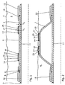
- Fig. 1 shows an annular barrier 1 to be expanded in an annulus 2 between a well tubular structure 3 and an inside wall 4 of a borehole 5.
- the annular barrier is expanded, as shown in Fig. 2 , to isolate a production zone downhole.
- the annular barrier as shown in Fig. 1 and Fig. 2 does not comprise the sealing element (see Figs. 3-17 ) according to the invention.
- the annular barrier is expanded using a pressure of up to 6000 PSI. When the annular barrier has been expanded, it may be exposed to continuous differential pressure or a periodically high pressure within the annulus, and the annular barrier therefore needs to contain this differential pressure and prevent a leak across the barrier.
- the annular barrier 1 comprises a tubular part 6 for mounting as part of the well tubular structure 3, the tubular part 6 having a longitudinal axis.
- the annular barrier 1 is thus assembled as part of the casing string.
- the annular barrier 1 comprises an expandable sleeve 7 surrounding the tubular part 6 and having an outer face 8, and each end 9, 10 of the expandable sleeve is fastened to the tubular part by means of a connection part 12.
- the annular barrier has an aperture 11 in the expandable sleeve 7 or the connection part 12 for pressurising the cavity between the expandable sleeve 7 and the tubular part 6 in order to expand the sleeve so that it presses against an inner wall of the borehole 5.
- a first connection 14 and a second connection 15 of a safety sleeve are fastened on the outer face of the expandable sleeve, and the safety sleeve 16 has an opening 17 and a sleeve part 25 which is thus fastened to the expandable sleeve by means of the first and the second connections.
- the safety sleeve 16 and the outer face 8 of the expandable sleeve 7 define a space 13 which is in fluid communication with the annulus through the opening 17 opposite one of the connections when the expandable sleeve is expanded, as illustrated with arrows in Fig. 2 .
- the formation pressure in the annulus Pa has increased, and fluid is pressed in through the opening 17 and into the space 13 under the sleeve part 25 of the safety sleeve 16, and the sleeve part 25 is thereby expanded so that it presses against the inner wall of the borehole, maintaining the sealing ability of the annular barrier 1.
- the expandable sleeve 7 is not influenced during expansion of the safety sleeve 16.
- the sleeve part 25 of the safety sleeve 16 has a thickness t 1 which is less than a thickness t 2 of the expandable sleeve 7.
- the sleeve part 25 of the safety sleeve 16 is ring-shaped and is fastened to each connection along its entire circumference, providing an enclosed space 13 between the safety sleeve 16 and the expandable sleeve 7, thus fluid communication with the space 13 can only happen through the opening 17.
- the connections 14, 15 are also ring-shaped and fastened to the expandable sleeve by means of welding, press-fitting or similar fastening.
- the safety sleeve 16 is made of metal having a lower E-modulus than that of the expandable sleeve 7.
- the sleeve part 25 of the safety sleeve 16 may also be made of polymers, such as an elastomeric material, silicone, or natural or syntactic rubber.
- a sealing element 18 is arranged on an outer face 19 of the sleeve part 25 of the safety sleeve 16.
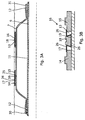
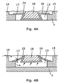
- the safety sleeve 16 has a recess 20 in that the sleeve part 25 has a trapezoidal shape in the cross-sectional view of Figs. 3B and 4A , and the sealing element 18 is arranged in that recess 20.
- the sealing element 18 is ring-shaped and has a corresponding cross-sectional trapezoidal shape.
- the sleeve part 25 of the safety sleeve 16 is fastened to the connections 14, 15 by means of small rings.
- the sleeve part 25 of the safety sleeve 16 is connected with the connection rings 14, 15 at a distance from the recess, resulting in a distance safety sleeve part 26 on either side of the recess between the recess and the connections.
- the opening is arranged in one of the distance safety sleeve parts so that when two or more safety sleeves are arranged on one annular barrier, as shown in Fig.
- the opening in the safety sleeve 16 closest to one connection part 12 is positioned in the distance safety sleeve part 26 closest to that connection part 12. Furthermore, the opening of the safety sleeve 16 closest to the second connection part 12 is positioned in the distance safety sleeve part 26 closest to that second connection part 12.
- the openings are arranged closest to the annulus, and the formation pressure can easily activate the safety sleeve 16 so that the sealing element 18 is forced towards the borehole wall when the formation pressure increases.
- one connection part is fixedly fastened to the tubular part 6 and another connection part is slidably arranged on the tubular part 6. Two sealing elements, such as O-rings, are arranged between the slidable connection part and the tubular part.
- connection 14, 15 are larger rings than those shown in Fig. 3A and are capable of restricting the expansion of the expandable sleeve so that the expandable sleeve 7 is prevented from being freely expanded. This results in circumferential grooves being formed in the expandable sleeve, strengthening the expandable sleeve 7 to withstand a higher pressure before collapsing.
- the sleeve part 25 of the safety sleeve 16 is ring-shaped and may have a variety of different cross-sectional shapes, e.g. a regular plate shape without any recesses.
- the plate-shaped sleeve part 25 of the safety sleeve may have a plate-shaped sealing element, as shown in Fig. 6 .
- the safety sleeve 16 is fastened to the expandable sleeve 7 by means of welding connections 14, 15.
- the safety sleeve 16 has a recess 20, and in cross-section, the sleeve part 25 of the safety sleeve 16 has a triangular or M-shaped cross-section, and a space 13 is present between the safety sleeve 16 and the outer face of the expandable sleeve 7.
- the safety sleeve 16 has an opening 17 so that the space is in fluid communication with the annulus.
- the recess 20 in the sleeve part 25 of the safety sleeve 16 has, in a cross-section along the longitudinal axis of the tubular part, a square shape, a triangular shape or a trapezoidal shape, as shown in Figs. 8-10 .
- the recess is trapezoidal, and two sealing elements 18 arranged in the recess have a corresponding trapezoidal shape.
- the recess has a square shape, and sealing elements 18 arranged therein also have a square cross-section.
- the recess is triangular in cross-section, and one sealing element 18 arranged in the recess has a round cross-section, such as an O-ring.
- Each of the sleeve parts 25 of the safety sleeves of Figs. 8-10 has an opening 17 for letting well fluid in and expanding the sleeve part 25 of the safety sleeve 16 so that the sealing elements 18 are pressed towards the wall of the borehole to sealingly engage the wall.
- the sealing element extends radially beyond the rings from the expandable sleeve 7 so that when the expandable sleeve is expanded, the sealing elements sealingly engage the wall of the borehole.
- a one-way valve may be arranged in the opening.
- the annular barrier 1 may comprise a plurality of safety sleeves 16 being a plurality of connection rings and a plurality of sleeve parts 25 of the safety sleeves arranged between the connection rings, as shown in Fig. 11 .
- the openings in the safety sleeves are arranged so that three openings face a first end 34 of the annular barrier and the other three openings of the safety sleeves face a second end 35 of the annular barrier.
- the opening 17 in a first safety sleeve positioned closest to the first end is arranged closer to the first end than the second end in relation to a middle part 27 of the first safety sleeve
- the opening in a second safety sleeve positioned closest to the second end is arranged closer to the second end than the first end in relation to a middle part 27 of the second safety sleeve.
- the safety sleeve 16 comprises a sleeve part 25 and two connections 14, 15 wherein the second connection 15 connects the sleeve part with the expandable sleeve 7.
- the sleeve part 25 is free to move in relation to the first connection, creating an opening 17 so that the fluid can flow between the space and the annulus opposite the first connection 14, as shown.
- the sleeve part has a recess in which the sealing element is arranged so that when the pressure in the annulus increases, the fluid flows past the connection through the opening 17 between the sleeve part 25 and the first connection 14 and presses the sleeve part and the sealing element against the formation wall.
- the opening is arranged between the first connection and the expandable sleeve 7 so that fluid is allowed to flow underneath the first connection.
- the opening may be a groove made as a longitudinal groove in the bottom of the first connection along the longitudinal axis of the tubular part.
- the safety sleeve 16 in Fig. 14 is made as one part so that the first and second connections 14, 15 are integral part of the sleeve part 25.
- the safety sleeve may, in this embodiment, be machined from one metal piece to obtain a trapeze-shape providing a recess in which the sealing element 18 is arranged.
- the fluid from the annulus surrounding the first connection is allowed to flow into the space 13 in order to press on the safety sleeve and force the sleeve against the formation.
- the first connection is not connected or only partly connected with the expandable sleeve, and the second connection 15 is fixedly connected with the expandable sleeve 7.
- the safety sleeve of Fig. 15A further comprises a sheet 28 arranged between the sleeve part and the expandable sleeve and at least partly circumferencing the expandable sleeve 7.
- the sheet extends further along the expandable sleeve between the first connection 14 and the expandable sleeve 7.
- the sheet is pressed in between the first connection and the expandable sleeve.
- Fig. 15B shows a cross-section of the un-expanded annular barrier of Fig. 15A. In Fig. 15B, the sheet partly circumferents the expandable sleeve 7, providing a channel 29 being the opening 17 between the connection and the expandable sleeve.
- the annular barrier comprises an anchoring section 50 which is part of the expandable sleeve being provided with projection elements 51, such as spikes or barbs or similar projections. When expanded, the projection elements penetrate the formations and anchor the annular barrier along the longitudinal axis of the annular barrier.
- the projection elements 51 may also be formed as ring-shaped elements circumferencing the expandable sleeve.
- the projection elements 51 are arranged as part of the connections as peaking circumferential projections.
- the connections are ring-shaped and circumferent the expandable sleeve and end in two peaking points/circumferences when seen in cross-section, as illustrated in Fig. 17 .
- the expandable sleeve 7 of the annular barrier 1 When the expandable sleeve 7 of the annular barrier 1 is expanded, the diameter of the sleeve is expanded from its initial unexpanded diameter to a larger diameter.
- the expandable sleeve 7 has an outside diameter D and is capable of expanding to a diameter which is at least 10% larger, preferably at least 15% larger, more preferably at least 30% larger than that of an unexpanded sleeve 7.
- the expandable sleeve 7 has a wall thickness t which is thinner than a length of the expandable sleeve, the thickness preferably being less than 25% of the length, more preferably less than 15% of the length, and even more preferably less than 10% of the length.
- the expandable sleeve 7 of the annular barrier 1 is made of a first metal having an elongation of 35-70%, at least 40%, preferably 40-50%, and the connection part 12 is made of a second metal having an elongation of 10-35%, preferably 25-35%.
- the metal of the connection part 12 has an elongation of at least 5 percentage points, preferably at least 10 percentage points higher than the elongation of the metal of the expandable sleeve.
- the yield strength (soft annealed) of the metal of the expandable sleeve is 200-400 MPa, preferably 200-300 MPa.
- the yield strength (cold worked) of the metal of the connection part is 500-1000 MPa, preferably 500-700 MPa.
- the first metal is more flexible than the second metal.
- connection parts 12 of the annular barrier may be fixedly fastened to the tubular part, and with maximum diametrical expansion capability, this is considered beneficial since it eliminates any moving parts and obviates the need for expensive and risky high pressure seals within these moving parts. This is particularly important when considering high temperature or corrosive well environments, e.g. Acid, H2S etc.
- the annular barrier may be comprised in a downhole system comprising a well tubular structure 3 and a plurality of annular barriers spaced apart along the well tubular structure to isolate a production zone.
- the annular barriers may be expanded by pressurising the well tubular structure 3 from within by means of drill pipe or by means of a tool submersible into the well tubular structure and capable of isolating a part of the well tubular structure.
- the tool may comprise a downhole tractor, such as a Well Tractor®.
- the tool may also use coiled tubing for expanding the expandable sleeve 7 of one annular barrier or two annular barriers 1 at the same time.
- a tool with coiled tubing can pressurise the fluid in the well tubular structure 3 without having to isolate a section of the well tubular structure.
- the tool may need to plug the well tubular structure further down the borehole for the two annular barriers 1 to be operated.
- the safety sleeve is expanded automatically when the formation pressure increases.
- the expanded safety sleeve is expanded by inserting an annular barrier as part of the well tubular structure in the borehole having a well pressure, and subsequently expanding the expandable sleeve by injecting pressurised fluid into the aperture 11 of the annular barrier.
- the safety sleeve is expanded by means of well fluid forcing the sealing element in sealing contact with the wall of the borehole when the well pressure becomes higher than a predetermined pressure.
- the tool comprises a reservoir containing the pressurised fluid, e.g. when the fluid used for expanding the sleeve is cement, gas, or a two-component compound.
- An annular barrier 1 may also be called a packer or similar expandable means.
- the well tubular structure can be the production tubing or casing or a similar kind of tubing downhole in a well or a borehole.
- the annular barrier 1 can be used both between the inner production tubing and an outer tubing in the borehole or between a tubing and the inner wall of the borehole.
- a well may have several kinds of tubing, and the annular barrier 1 of the present invention can be mounted for use in all of these.
- the valve 19 may be any kind of valve capable of controlling flow, such as a ball valve, butterfly valve, choke valve, check valve or non-return valve, diaphragm valve, expansion valve, gate valve, globe valve, knife valve, needle valve, piston valve, pinch valve or plug valve.
- a ball valve such as a ball valve, butterfly valve, choke valve, check valve or non-return valve, diaphragm valve, expansion valve, gate valve, globe valve, knife valve, needle valve, piston valve, pinch valve or plug valve.
- the expandable tubular metal sleeve 7 may be a cold-drawn or hot-drawn tubular structure.
- the fluid used for expanding the expandable sleeve 7 may be any kind of well fluid present in the borehole surrounding the tool and/or the well tubular structure 3.
- the fluid may be cement, gas, water, polymers, or a two-component compound, such as powder or particles mixing or reacting with a binding or hardening agent.
- Part of the fluid, such as the hardening agent may be present in the cavity between the tubular part and the expandable sleeve before injecting a subsequent fluid into the cavity.
Landscapes
- Geology (AREA)
- Life Sciences & Earth Sciences (AREA)
- Engineering & Computer Science (AREA)
- Mining & Mineral Resources (AREA)
- Geochemistry & Mineralogy (AREA)
- Fluid Mechanics (AREA)
- Environmental & Geological Engineering (AREA)
- General Life Sciences & Earth Sciences (AREA)
- Physics & Mathematics (AREA)
- Filling Or Discharging Of Gas Storage Vessels (AREA)
- Pipe Accessories (AREA)
- Laying Of Electric Cables Or Lines Outside (AREA)
- Quick-Acting Or Multi-Walled Pipe Joints (AREA)
- Earth Drilling (AREA)
- Gasket Seals (AREA)
- Consolidation Of Soil By Introduction Of Solidifying Substances Into Soil (AREA)
Claims (14)
- Barrière annulaire (1) destinée à être expansée dans un espace annulaire (2) qui comprend du fluide de puits et est agencée entre une structure tubulaire de puits (3) et une paroi intérieure (4) d'un fond de trou de forage (5), la barrière annulaire comprenant :- une partie tubulaire (6) destinée à être montée en tant que partie de la structure tubulaire de puits (3), la partie tubulaire ayant un axe longitudinal,- un manchon expansible (7) entourant la partie tubulaire et ayant une face externe (8), chaque extrémité (9, 10) du manchon expansible étant fixée sur la partie tubulaire au moyen d'une partie de raccordement (12),- une ouverture (11) dans la partie tubulaire ou la partie de raccordement, et- un manchon de sécurité (16) ayant un premier raccordement (14) et un second raccordement (15) pour fixer le manchon de sécurité sur la face externe du manchon expansible et une ouverture (17) en raccordement avec le manchon de sécurité, le manchon de sécurité et le manchon expansible définissant un espace (13) qui est en communication de fluide avec l'espace annulaire par le biais de l'ouverture,caractérisée en ce que le manchon de sécurité a une partie centrale agencée entre deux raccordements et en ce qu'un élément d'étanchéité (18) est agencé au niveau de la partie centrale sur une face externe (19) du manchon de sécurité, et
en ce que l'ouverture est agencée plus à proximité de l'un des raccordements que la partie centrale, permettant la communication de fluide entre l'espace et l'espace annulaire opposé à l'un des raccordements par le biais de l'ouverture. - Barrière annulaire selon la revendication 1, dans laquelle le manchon de sécurité a une extension le long de l'axe longitudinal de la partie tubulaire qui est inférieure à 30% d'une extension du manchon expansible le long de l'axe longitudinal de la partie tubulaire, de préférence inférieure à 20% de l'extension du manchon expansible, encore de préférence inférieure à 10% de l'extension du manchon expansible.
- Barrière annulaire selon la revendication 1 ou 2, dans laquelle le manchon de sécurité comprend une partie de manchon (25) qui est fixée au manchon expansible au moyen d'au moins l'un des seconds raccordements et ayant une épaisseur (t1) qui est inférieure à une épaisseur (t2) du manchon expansible.
- Barrière annulaire selon l'une quelconque des revendications 1 à 3, dans laquelle le manchon de sécurité est réalisé avec un matériau ayant un module E inférieur à celui du manchon expansible.
- Barrière annulaire selon l'une quelconque des revendications précédentes, dans laquelle le manchon de sécurité comprend un évidement (20).
- Barrière annulaire selon la revendication 5, dans laquelle un élément d'étanchéité (18) est agencé dans l'évidement.
- Barrière annulaire selon l'une quelconque des revendications précédentes, dans laquelle l'ouverture est agencée entre l'un des raccordements et l'évidement.
- Barrière annulaire selon l'une quelconque des revendications précédentes, dans laquelle l'ouverture est agencée entre l'un des raccordements et le manchon expansible.
- Barrière annulaire selon la revendication 8, dans laquelle l'ouverture est prévue sous la forme d'une rainure dans l'un des raccordements le long de l'axe longitudinal de la partie tubulaire.
- Barrière annulaire selon l'une quelconque des revendications précédentes, dans laquelle le manchon de sécurité comprend une partie de manchon fixée au manchon expansible au moyen d'au moins l'un des raccordements et d'une feuille (28) agencée entre la partie de manchon et le manchon expansible et entourant au moins partiellement le manchon expansible.
- Barrière annulaire selon la revendication 10, dans laquelle la feuille entoure partiellement le manchon expansible, fournissant un canal (29) qui est l'ouverture entre le raccordement et le manchon expansible.
- Barrière annulaire selon l'une quelconque des revendications précédentes, dans laquelle les premier et second raccordements sont des anneaux de raccordement, la barrière annulaire comprend une pluralité d'anneaux de raccordement et une pluralité de manchons de sécurité agencés entre les anneaux de raccordement, et la barrière annulaire a une première extrémité et une seconde extrémité et l'ouverture dans le premier manchon de sécurité positionnée le plus à proximité de la première extrémité est agencée plus près de la première extrémité que de la seconde extrémité par rapport à une partie centrale du premier manchon de sécurité, et l'ouverture dans un second manchon de sécurité positionné le plus à proximité de la seconde extrémité est agencée plus près de la seconde extrémité que de la première extrémité par rapport à une partie centrale du second manchon de sécurité.
- Système de fond de trou comprenant une structure tubulaire de puits et au moins une barrière annulaire selon l'une quelconque des revendications 1 à 12.
- Procédé pour maintenir un joint d'étanchéité caractérisé en ce qu'il comprend les étapes consistant à :- insérer une barrière annulaire selon l'une quelconque des revendications 1 à 12 dans le forage ayant une pression de puits,- expanser le manchon expansible en injectant le fluide sous pression dans l'ouverture, et- expanser le manchon de sécurité pour forcer l'élément d'étanchéité en contact d'étanchéité avec la paroi du forage lorsque la pression de puits devient supérieure à une pression prédéterminée.
Priority Applications (1)
| Application Number | Priority Date | Filing Date | Title |
|---|---|---|---|
| EP12732597.5A EP2723976B1 (fr) | 2011-06-23 | 2012-06-22 | Barrière annulaire avec joint externe |
Applications Claiming Priority (3)
| Application Number | Priority Date | Filing Date | Title |
|---|---|---|---|
| EP11171168A EP2538018A1 (fr) | 2011-06-23 | 2011-06-23 | Barrière annulaire dotée d'un joint externe |
| PCT/EP2012/062120 WO2012175695A1 (fr) | 2011-06-23 | 2012-06-22 | Barrière annulaire avec joint externe |
| EP12732597.5A EP2723976B1 (fr) | 2011-06-23 | 2012-06-22 | Barrière annulaire avec joint externe |
Publications (2)
| Publication Number | Publication Date |
|---|---|
| EP2723976A1 EP2723976A1 (fr) | 2014-04-30 |
| EP2723976B1 true EP2723976B1 (fr) | 2016-06-08 |
Family
ID=46458477
Family Applications (2)
| Application Number | Title | Priority Date | Filing Date |
|---|---|---|---|
| EP11171168A Withdrawn EP2538018A1 (fr) | 2011-06-23 | 2011-06-23 | Barrière annulaire dotée d'un joint externe |
| EP12732597.5A Active EP2723976B1 (fr) | 2011-06-23 | 2012-06-22 | Barrière annulaire avec joint externe |
Family Applications Before (1)
| Application Number | Title | Priority Date | Filing Date |
|---|---|---|---|
| EP11171168A Withdrawn EP2538018A1 (fr) | 2011-06-23 | 2011-06-23 | Barrière annulaire dotée d'un joint externe |
Country Status (11)
| Country | Link |
|---|---|
| US (1) | US9206666B2 (fr) |
| EP (2) | EP2538018A1 (fr) |
| CN (1) | CN103620156B (fr) |
| AU (1) | AU2012273958B2 (fr) |
| BR (1) | BR112013032433B1 (fr) |
| CA (1) | CA2840140C (fr) |
| DK (1) | DK2723976T3 (fr) |
| MX (1) | MX339224B (fr) |
| MY (1) | MY168260A (fr) |
| RU (1) | RU2590664C2 (fr) |
| WO (1) | WO2012175695A1 (fr) |
Families Citing this family (20)
| Publication number | Priority date | Publication date | Assignee | Title |
|---|---|---|---|---|
| EP2607613A1 (fr) * | 2011-12-21 | 2013-06-26 | Welltec A/S | Barrière annulaire avec dispositif à actionnement automatique |
| EP2789791A1 (fr) | 2013-04-12 | 2014-10-15 | Welltec A/S | Élément tubulaire extensible de fond de trou |
| US10208550B2 (en) * | 2013-05-07 | 2019-02-19 | Baker Hughes, A Ge Company, Llc | Anchoring device, system and method of attaching an anchor to a tubular |
| FR3010130B1 (fr) * | 2013-08-28 | 2015-10-02 | Saltel Ind | Element tubulaire avec etancheite dynamique et son procede d'application contre la paroi d'un puits |
| EP2963232A1 (fr) * | 2014-06-30 | 2016-01-06 | Welltec A/S | Dispositif de commande d'écoulement de fond de trou |
| CA2985715A1 (fr) * | 2015-05-26 | 2016-12-01 | Welltec A/S | Barriere annulaire ayant un tubulaire de fond de trou expansible |
| GB2552799B (en) * | 2016-08-09 | 2019-05-22 | Morphpackers Ltd | Morphable packer |
| WO2018070999A1 (fr) * | 2016-10-11 | 2018-04-19 | Halliburton Energy Services, Inc. | Manchon protecteur soluble |
| GB201710376D0 (en) * | 2017-06-28 | 2017-08-16 | Peak Well Systems Pty Ltd | Seal apparatus and methods of use |
| CN110892133A (zh) * | 2017-07-27 | 2020-03-17 | 韦尔泰克油田解决方案股份公司 | 用于小直径井的环状屏障 |
| CA3084273A1 (fr) * | 2017-12-12 | 2019-06-20 | Welltec Oilfield Solutions Ag | Bouchon d'abandon et systeme de bouchage et d'abandon |
| WO2019194813A1 (fr) * | 2018-04-05 | 2019-10-10 | Halliburton Energy Services, Inc. | Dispositif d'isolation de puits de forage |
| US11814920B2 (en) | 2019-01-21 | 2023-11-14 | Schlumberger Technology Corporation | System and methodology for through tubing patching |
| US11788365B2 (en) | 2019-01-23 | 2023-10-17 | Saltel Industries Sas | Expandable metal packer system with pressure control device |
| EP3999712A1 (fr) | 2019-07-19 | 2022-05-25 | DynaEnergetics Europe GmbH | Outil de puits de forage à actionnement balistique |
| US12084962B2 (en) | 2020-03-16 | 2024-09-10 | DynaEnergetics Europe GmbH | Tandem seal adapter with integrated tracer material |
| CN113266303B (zh) * | 2021-06-28 | 2024-05-07 | 安东柏林石油科技(北京)有限公司 | 提高连续封隔体沿井筒轴向封隔效果的封隔器、方法及完井结构 |
| US12480374B2 (en) * | 2024-02-16 | 2025-11-25 | Halliburton Energy Services, Inc. | Expandable tubular structure for maintaining differential pressure integrity in a wellbore |
| US12435604B2 (en) * | 2024-02-28 | 2025-10-07 | Halliburton Energy Services, Inc. | Fluoroplastic expandable liner hanger elements for geothermal and corrosive environments |
| EP4650563A1 (fr) * | 2024-05-17 | 2025-11-19 | Welltec Manufacturing Center Completions ApS | Composant de complétion |
Family Cites Families (18)
| Publication number | Priority date | Publication date | Assignee | Title |
|---|---|---|---|---|
| US3044553A (en) * | 1958-05-05 | 1962-07-17 | Halliburton Co | Well packer |
| US3272517A (en) * | 1963-07-08 | 1966-09-13 | Pan American Petroleum Corp | Casing packer |
| US3428124A (en) * | 1967-02-03 | 1969-02-18 | Robert Armstrong | Apparatus and method for sealing deep wells |
| GB2248255B (en) * | 1990-09-27 | 1994-11-16 | Solinst Canada Ltd | Borehole packer |
| US5184677A (en) * | 1991-05-10 | 1993-02-09 | Gas Research Institute | Pass-through zone isolation packer and process for isolating zones in a multiple-zone well |
| CA2169382C (fr) * | 1996-02-13 | 2003-08-05 | Marvin L. Holbert | Methode et appareil pour le gonflage de packer dans un puits de forage |
| RU2128279C1 (ru) * | 1997-06-16 | 1999-03-27 | Закрытое акционерное общество "ЮКСОН" | Надувной гидравлический пакер |
| RU2135739C1 (ru) * | 1998-01-05 | 1999-08-27 | Пшеничный Павел Леонтьевич | Якорь-пакер пшеничного п.л. |
| AU2002225233B2 (en) * | 2001-01-26 | 2007-08-02 | E2 Tech Limited | Device and method to seal boreholes |
| US7152687B2 (en) * | 2003-11-06 | 2006-12-26 | Halliburton Energy Services, Inc. | Expandable tubular with port valve |
| US6854522B2 (en) * | 2002-09-23 | 2005-02-15 | Halliburton Energy Services, Inc. | Annular isolators for expandable tubulars in wellbores |
| US7347274B2 (en) * | 2004-01-27 | 2008-03-25 | Schlumberger Technology Corporation | Annular barrier tool |
| GB0417328D0 (en) * | 2004-08-04 | 2004-09-08 | Read Well Services Ltd | Apparatus and method |
| US7392851B2 (en) * | 2004-11-04 | 2008-07-01 | Schlumberger Technology Corporation | Inflatable packer assembly |
| US7387165B2 (en) * | 2004-12-14 | 2008-06-17 | Schlumberger Technology Corporation | System for completing multiple well intervals |
| US7387157B2 (en) * | 2005-09-14 | 2008-06-17 | Schlumberger Technology Corporation | Dynamic inflatable sealing device |
| ES2464457T3 (es) * | 2009-01-12 | 2014-06-02 | Welltec A/S | Barrera anular y sistema de barrera anular |
| EP2312119A1 (fr) * | 2009-10-07 | 2011-04-20 | Welltec A/S | Barrière annulaire |
-
2011
- 2011-06-23 EP EP11171168A patent/EP2538018A1/fr not_active Withdrawn
-
2012
- 2012-06-22 AU AU2012273958A patent/AU2012273958B2/en not_active Ceased
- 2012-06-22 WO PCT/EP2012/062120 patent/WO2012175695A1/fr not_active Ceased
- 2012-06-22 CN CN201280030870.2A patent/CN103620156B/zh not_active Expired - Fee Related
- 2012-06-22 EP EP12732597.5A patent/EP2723976B1/fr active Active
- 2012-06-22 MX MX2013013823A patent/MX339224B/es active IP Right Grant
- 2012-06-22 MY MYPI2013004548A patent/MY168260A/en unknown
- 2012-06-22 DK DK12732597.5T patent/DK2723976T3/en active
- 2012-06-22 BR BR112013032433-3A patent/BR112013032433B1/pt not_active IP Right Cessation
- 2012-06-22 RU RU2014101956/03A patent/RU2590664C2/ru active
- 2012-06-22 US US14/128,705 patent/US9206666B2/en active Active
- 2012-06-22 CA CA2840140A patent/CA2840140C/fr not_active Expired - Fee Related
Also Published As
| Publication number | Publication date |
|---|---|
| MX2013013823A (es) | 2014-02-27 |
| RU2014101956A (ru) | 2015-07-27 |
| EP2538018A1 (fr) | 2012-12-26 |
| DK2723976T3 (en) | 2016-09-19 |
| US9206666B2 (en) | 2015-12-08 |
| RU2590664C2 (ru) | 2016-07-10 |
| CA2840140A1 (fr) | 2012-12-27 |
| AU2012273958A1 (en) | 2013-05-02 |
| BR112013032433A2 (pt) | 2017-01-17 |
| CN103620156B (zh) | 2016-11-02 |
| CN103620156A (zh) | 2014-03-05 |
| MX339224B (es) | 2016-05-17 |
| EP2723976A1 (fr) | 2014-04-30 |
| MY168260A (en) | 2018-10-16 |
| CA2840140C (fr) | 2019-07-16 |
| BR112013032433B1 (pt) | 2020-12-01 |
| US20140145402A1 (en) | 2014-05-29 |
| AU2012273958B2 (en) | 2015-03-12 |
| WO2012175695A1 (fr) | 2012-12-27 |
Similar Documents
| Publication | Publication Date | Title |
|---|---|---|
| EP2723976B1 (fr) | Barrière annulaire avec joint externe | |
| EP2706189B1 (fr) | Barrière annulaire dotée d'une membrane | |
| CA2813896C (fr) | Barriere annulaire | |
| EP2312119A1 (fr) | Barrière annulaire | |
| US20150034316A1 (en) | Annular barrier having expansion tubes | |
| AU2013241857B2 (en) | An annular barrier having a flexible connection | |
| EP2625375B1 (fr) | Barrière annulaire | |
| AU2013100386B4 (en) | Annular barrier | |
| AU2013100385B4 (en) | Annular barrier | |
| AU2013100388B4 (en) | Annular barrier | |
| AU2013100387B4 (en) | Annular barrier |
Legal Events
| Date | Code | Title | Description |
|---|---|---|---|
| PUAI | Public reference made under article 153(3) epc to a published international application that has entered the european phase |
Free format text: ORIGINAL CODE: 0009012 |
|
| 17P | Request for examination filed |
Effective date: 20131204 |
|
| AK | Designated contracting states |
Kind code of ref document: A1 Designated state(s): AL AT BE BG CH CY CZ DE DK EE ES FI FR GB GR HR HU IE IS IT LI LT LU LV MC MK MT NL NO PL PT RO RS SE SI SK SM TR |
|
| DAX | Request for extension of the european patent (deleted) | ||
| GRAP | Despatch of communication of intention to grant a patent |
Free format text: ORIGINAL CODE: EPIDOSNIGR1 |
|
| INTG | Intention to grant announced |
Effective date: 20150828 |
|
| GRAS | Grant fee paid |
Free format text: ORIGINAL CODE: EPIDOSNIGR3 |
|
| INTG | Intention to grant announced |
Effective date: 20160105 |
|
| GRAA | (expected) grant |
Free format text: ORIGINAL CODE: 0009210 |
|
| AK | Designated contracting states |
Kind code of ref document: B1 Designated state(s): AL AT BE BG CH CY CZ DE DK EE ES FI FR GB GR HR HU IE IS IT LI LT LU LV MC MK MT NL NO PL PT RO RS SE SI SK SM TR |
|
| REG | Reference to a national code |
Ref country code: GB Ref legal event code: FG4D |
|
| REG | Reference to a national code |
Ref country code: CH Ref legal event code: EP |
|
| REG | Reference to a national code |
Ref country code: IE Ref legal event code: FG4D |
|
| REG | Reference to a national code |
Ref country code: AT Ref legal event code: REF Ref document number: 805395 Country of ref document: AT Kind code of ref document: T Effective date: 20160715 |
|
| REG | Reference to a national code |
Ref country code: DE Ref legal event code: R096 Ref document number: 602012019389 Country of ref document: DE |
|
| REG | Reference to a national code |
Ref country code: FR Ref legal event code: PLFP Year of fee payment: 5 |
|
| REG | Reference to a national code |
Ref country code: NL Ref legal event code: FP |
|
| REG | Reference to a national code |
Ref country code: DK Ref legal event code: T3 Effective date: 20160912 |
|
| REG | Reference to a national code |
Ref country code: LT Ref legal event code: MG4D |
|
| PG25 | Lapsed in a contracting state [announced via postgrant information from national office to epo] |
Ref country code: NO Free format text: LAPSE BECAUSE OF FAILURE TO SUBMIT A TRANSLATION OF THE DESCRIPTION OR TO PAY THE FEE WITHIN THE PRESCRIBED TIME-LIMIT Effective date: 20160908 Ref country code: LT Free format text: LAPSE BECAUSE OF FAILURE TO SUBMIT A TRANSLATION OF THE DESCRIPTION OR TO PAY THE FEE WITHIN THE PRESCRIBED TIME-LIMIT Effective date: 20160608 Ref country code: FI Free format text: LAPSE BECAUSE OF FAILURE TO SUBMIT A TRANSLATION OF THE DESCRIPTION OR TO PAY THE FEE WITHIN THE PRESCRIBED TIME-LIMIT Effective date: 20160608 |
|
| REG | Reference to a national code |
Ref country code: AT Ref legal event code: MK05 Ref document number: 805395 Country of ref document: AT Kind code of ref document: T Effective date: 20160608 |
|
| PG25 | Lapsed in a contracting state [announced via postgrant information from national office to epo] |
Ref country code: LV Free format text: LAPSE BECAUSE OF FAILURE TO SUBMIT A TRANSLATION OF THE DESCRIPTION OR TO PAY THE FEE WITHIN THE PRESCRIBED TIME-LIMIT Effective date: 20160608 Ref country code: SE Free format text: LAPSE BECAUSE OF FAILURE TO SUBMIT A TRANSLATION OF THE DESCRIPTION OR TO PAY THE FEE WITHIN THE PRESCRIBED TIME-LIMIT Effective date: 20160608 Ref country code: HR Free format text: LAPSE BECAUSE OF FAILURE TO SUBMIT A TRANSLATION OF THE DESCRIPTION OR TO PAY THE FEE WITHIN THE PRESCRIBED TIME-LIMIT Effective date: 20160608 Ref country code: ES Free format text: LAPSE BECAUSE OF FAILURE TO SUBMIT A TRANSLATION OF THE DESCRIPTION OR TO PAY THE FEE WITHIN THE PRESCRIBED TIME-LIMIT Effective date: 20160608 Ref country code: GR Free format text: LAPSE BECAUSE OF FAILURE TO SUBMIT A TRANSLATION OF THE DESCRIPTION OR TO PAY THE FEE WITHIN THE PRESCRIBED TIME-LIMIT Effective date: 20160909 Ref country code: RS Free format text: LAPSE BECAUSE OF FAILURE TO SUBMIT A TRANSLATION OF THE DESCRIPTION OR TO PAY THE FEE WITHIN THE PRESCRIBED TIME-LIMIT Effective date: 20160608 |
|
| PG25 | Lapsed in a contracting state [announced via postgrant information from national office to epo] |
Ref country code: BE Free format text: LAPSE BECAUSE OF NON-PAYMENT OF DUE FEES Effective date: 20160630 |
|
| REG | Reference to a national code |
Ref country code: NO Ref legal event code: RE |
|
| PG25 | Lapsed in a contracting state [announced via postgrant information from national office to epo] |
Ref country code: RO Free format text: LAPSE BECAUSE OF FAILURE TO SUBMIT A TRANSLATION OF THE DESCRIPTION OR TO PAY THE FEE WITHIN THE PRESCRIBED TIME-LIMIT Effective date: 20160608 Ref country code: SK Free format text: LAPSE BECAUSE OF FAILURE TO SUBMIT A TRANSLATION OF THE DESCRIPTION OR TO PAY THE FEE WITHIN THE PRESCRIBED TIME-LIMIT Effective date: 20160608 Ref country code: CZ Free format text: LAPSE BECAUSE OF FAILURE TO SUBMIT A TRANSLATION OF THE DESCRIPTION OR TO PAY THE FEE WITHIN THE PRESCRIBED TIME-LIMIT Effective date: 20160608 Ref country code: IS Free format text: LAPSE BECAUSE OF FAILURE TO SUBMIT A TRANSLATION OF THE DESCRIPTION OR TO PAY THE FEE WITHIN THE PRESCRIBED TIME-LIMIT Effective date: 20161008 Ref country code: IT Free format text: LAPSE BECAUSE OF FAILURE TO SUBMIT A TRANSLATION OF THE DESCRIPTION OR TO PAY THE FEE WITHIN THE PRESCRIBED TIME-LIMIT Effective date: 20160608 Ref country code: EE Free format text: LAPSE BECAUSE OF FAILURE TO SUBMIT A TRANSLATION OF THE DESCRIPTION OR TO PAY THE FEE WITHIN THE PRESCRIBED TIME-LIMIT Effective date: 20160608 |
|
| REG | Reference to a national code |
Ref country code: CH Ref legal event code: PL |
|
| REG | Reference to a national code |
Ref country code: NO Ref legal event code: T2 Effective date: 20160608 |
|
| PG25 | Lapsed in a contracting state [announced via postgrant information from national office to epo] |
Ref country code: PL Free format text: LAPSE BECAUSE OF FAILURE TO SUBMIT A TRANSLATION OF THE DESCRIPTION OR TO PAY THE FEE WITHIN THE PRESCRIBED TIME-LIMIT Effective date: 20160608 Ref country code: AT Free format text: LAPSE BECAUSE OF FAILURE TO SUBMIT A TRANSLATION OF THE DESCRIPTION OR TO PAY THE FEE WITHIN THE PRESCRIBED TIME-LIMIT Effective date: 20160608 Ref country code: BE Free format text: LAPSE BECAUSE OF FAILURE TO SUBMIT A TRANSLATION OF THE DESCRIPTION OR TO PAY THE FEE WITHIN THE PRESCRIBED TIME-LIMIT Effective date: 20160608 Ref country code: PT Free format text: LAPSE BECAUSE OF FAILURE TO SUBMIT A TRANSLATION OF THE DESCRIPTION OR TO PAY THE FEE WITHIN THE PRESCRIBED TIME-LIMIT Effective date: 20161010 Ref country code: SM Free format text: LAPSE BECAUSE OF FAILURE TO SUBMIT A TRANSLATION OF THE DESCRIPTION OR TO PAY THE FEE WITHIN THE PRESCRIBED TIME-LIMIT Effective date: 20160608 |
|
| REG | Reference to a national code |
Ref country code: DE Ref legal event code: R097 Ref document number: 602012019389 Country of ref document: DE |
|
| REG | Reference to a national code |
Ref country code: IE Ref legal event code: MM4A |
|
| PG25 | Lapsed in a contracting state [announced via postgrant information from national office to epo] |
Ref country code: MC Free format text: LAPSE BECAUSE OF FAILURE TO SUBMIT A TRANSLATION OF THE DESCRIPTION OR TO PAY THE FEE WITHIN THE PRESCRIBED TIME-LIMIT Effective date: 20160608 |
|
| PLBE | No opposition filed within time limit |
Free format text: ORIGINAL CODE: 0009261 |
|
| STAA | Information on the status of an ep patent application or granted ep patent |
Free format text: STATUS: NO OPPOSITION FILED WITHIN TIME LIMIT |
|
| PG25 | Lapsed in a contracting state [announced via postgrant information from national office to epo] |
Ref country code: CH Free format text: LAPSE BECAUSE OF NON-PAYMENT OF DUE FEES Effective date: 20160630 Ref country code: LI Free format text: LAPSE BECAUSE OF NON-PAYMENT OF DUE FEES Effective date: 20160630 |
|
| 26N | No opposition filed |
Effective date: 20170309 |
|
| PG25 | Lapsed in a contracting state [announced via postgrant information from national office to epo] |
Ref country code: SI Free format text: LAPSE BECAUSE OF FAILURE TO SUBMIT A TRANSLATION OF THE DESCRIPTION OR TO PAY THE FEE WITHIN THE PRESCRIBED TIME-LIMIT Effective date: 20160608 Ref country code: IE Free format text: LAPSE BECAUSE OF NON-PAYMENT OF DUE FEES Effective date: 20160622 |
|
| REG | Reference to a national code |
Ref country code: FR Ref legal event code: PLFP Year of fee payment: 6 |
|
| PG25 | Lapsed in a contracting state [announced via postgrant information from national office to epo] |
Ref country code: HU Free format text: LAPSE BECAUSE OF FAILURE TO SUBMIT A TRANSLATION OF THE DESCRIPTION OR TO PAY THE FEE WITHIN THE PRESCRIBED TIME-LIMIT; INVALID AB INITIO Effective date: 20120622 |
|
| REG | Reference to a national code |
Ref country code: FR Ref legal event code: PLFP Year of fee payment: 7 |
|
| PG25 | Lapsed in a contracting state [announced via postgrant information from national office to epo] |
Ref country code: LU Free format text: LAPSE BECAUSE OF NON-PAYMENT OF DUE FEES Effective date: 20160622 Ref country code: MK Free format text: LAPSE BECAUSE OF FAILURE TO SUBMIT A TRANSLATION OF THE DESCRIPTION OR TO PAY THE FEE WITHIN THE PRESCRIBED TIME-LIMIT Effective date: 20160608 Ref country code: MT Free format text: LAPSE BECAUSE OF NON-PAYMENT OF DUE FEES Effective date: 20160630 Ref country code: CY Free format text: LAPSE BECAUSE OF FAILURE TO SUBMIT A TRANSLATION OF THE DESCRIPTION OR TO PAY THE FEE WITHIN THE PRESCRIBED TIME-LIMIT Effective date: 20160608 |
|
| PG25 | Lapsed in a contracting state [announced via postgrant information from national office to epo] |
Ref country code: BG Free format text: LAPSE BECAUSE OF FAILURE TO SUBMIT A TRANSLATION OF THE DESCRIPTION OR TO PAY THE FEE WITHIN THE PRESCRIBED TIME-LIMIT Effective date: 20160608 |
|
| PG25 | Lapsed in a contracting state [announced via postgrant information from national office to epo] |
Ref country code: AL Free format text: LAPSE BECAUSE OF FAILURE TO SUBMIT A TRANSLATION OF THE DESCRIPTION OR TO PAY THE FEE WITHIN THE PRESCRIBED TIME-LIMIT Effective date: 20160608 Ref country code: TR Free format text: LAPSE BECAUSE OF FAILURE TO SUBMIT A TRANSLATION OF THE DESCRIPTION OR TO PAY THE FEE WITHIN THE PRESCRIBED TIME-LIMIT Effective date: 20160608 |
|
| REG | Reference to a national code |
Ref country code: DE Ref legal event code: R082 Ref document number: 602012019389 Country of ref document: DE Representative=s name: SAMSON & PARTNER PATENTANWAELTE MBB, DE Ref country code: DE Ref legal event code: R081 Ref document number: 602012019389 Country of ref document: DE Owner name: WELLTEC OILFIELD SOLUTIONS AG, CH Free format text: FORMER OWNER: WELLTEC A/S, ALLEROED, DK |
|
| REG | Reference to a national code |
Ref country code: NO Ref legal event code: CHAD Owner name: WELLTEC OILFIELD SOLUTIONS AG, CH |
|
| REG | Reference to a national code |
Ref country code: GB Ref legal event code: 732E Free format text: REGISTERED BETWEEN 20190429 AND 20190502 |
|
| REG | Reference to a national code |
Ref country code: NL Ref legal event code: PD Owner name: WELLTEC OILFIELD SOLUTIONS AG; CH Free format text: DETAILS ASSIGNMENT: CHANGE OF OWNER(S), ASSIGNMENT; FORMER OWNER NAME: WELLTEC A/S Effective date: 20190607 |
|
| PGFP | Annual fee paid to national office [announced via postgrant information from national office to epo] |
Ref country code: FR Payment date: 20200623 Year of fee payment: 9 Ref country code: DE Payment date: 20200618 Year of fee payment: 9 |
|
| PGFP | Annual fee paid to national office [announced via postgrant information from national office to epo] |
Ref country code: NL Payment date: 20200617 Year of fee payment: 9 |
|
| REG | Reference to a national code |
Ref country code: DE Ref legal event code: R119 Ref document number: 602012019389 Country of ref document: DE |
|
| REG | Reference to a national code |
Ref country code: NL Ref legal event code: MM Effective date: 20210701 |
|
| PG25 | Lapsed in a contracting state [announced via postgrant information from national office to epo] |
Ref country code: DE Free format text: LAPSE BECAUSE OF NON-PAYMENT OF DUE FEES Effective date: 20220101 |
|
| PG25 | Lapsed in a contracting state [announced via postgrant information from national office to epo] |
Ref country code: NL Free format text: LAPSE BECAUSE OF NON-PAYMENT OF DUE FEES Effective date: 20210701 Ref country code: FR Free format text: LAPSE BECAUSE OF NON-PAYMENT OF DUE FEES Effective date: 20210630 |
|
| P01 | Opt-out of the competence of the unified patent court (upc) registered |
Effective date: 20230523 |
|
| REG | Reference to a national code |
Ref country code: GB Ref legal event code: 732E Free format text: REGISTERED BETWEEN 20241017 AND 20241023 |
|
| PGFP | Annual fee paid to national office [announced via postgrant information from national office to epo] |
Ref country code: GB Payment date: 20250618 Year of fee payment: 14 Ref country code: DK Payment date: 20250618 Year of fee payment: 14 |
|
| PGFP | Annual fee paid to national office [announced via postgrant information from national office to epo] |
Ref country code: NO Payment date: 20250618 Year of fee payment: 14 |