EP2724041B1 - Dispositif de transmission d'un couple - Google Patents
Dispositif de transmission d'un couple Download PDFInfo
- Publication number
- EP2724041B1 EP2724041B1 EP12734784.7A EP12734784A EP2724041B1 EP 2724041 B1 EP2724041 B1 EP 2724041B1 EP 12734784 A EP12734784 A EP 12734784A EP 2724041 B1 EP2724041 B1 EP 2724041B1
- Authority
- EP
- European Patent Office
- Prior art keywords
- assembly
- clutch
- leaf spring
- ring
- connection
- Prior art date
- Legal status (The legal status is an assumption and is not a legal conclusion. Google has not performed a legal analysis and makes no representation as to the accuracy of the status listed.)
- Not-in-force
Links
- 230000005540 biological transmission Effects 0.000 title claims description 13
- 230000000712 assembly Effects 0.000 claims description 8
- 238000000429 assembly Methods 0.000 claims description 8
- 230000009977 dual effect Effects 0.000 description 13
- 230000008878 coupling Effects 0.000 description 6
- 238000010168 coupling process Methods 0.000 description 6
- 238000005859 coupling reaction Methods 0.000 description 6
- 238000002485 combustion reaction Methods 0.000 description 3
- 239000002184 metal Substances 0.000 description 2
- 230000015572 biosynthetic process Effects 0.000 description 1
- 150000001875 compounds Chemical group 0.000 description 1
- 238000010276 construction Methods 0.000 description 1
- 238000006073 displacement reaction Methods 0.000 description 1
- 239000007858 starting material Substances 0.000 description 1
Images


Classifications
-
- F—MECHANICAL ENGINEERING; LIGHTING; HEATING; WEAPONS; BLASTING
- F16—ENGINEERING ELEMENTS AND UNITS; GENERAL MEASURES FOR PRODUCING AND MAINTAINING EFFECTIVE FUNCTIONING OF MACHINES OR INSTALLATIONS; THERMAL INSULATION IN GENERAL
- F16D—COUPLINGS FOR TRANSMITTING ROTATION; CLUTCHES; BRAKES
- F16D1/00—Couplings for rigidly connecting two coaxial shafts or other movable machine elements
- F16D1/10—Quick-acting couplings in which the parts are connected by simply bringing them together axially
- F16D1/101—Quick-acting couplings in which the parts are connected by simply bringing them together axially without axial retaining means rotating with the coupling
-
- F—MECHANICAL ENGINEERING; LIGHTING; HEATING; WEAPONS; BLASTING
- F16—ENGINEERING ELEMENTS AND UNITS; GENERAL MEASURES FOR PRODUCING AND MAINTAINING EFFECTIVE FUNCTIONING OF MACHINES OR INSTALLATIONS; THERMAL INSULATION IN GENERAL
- F16D—COUPLINGS FOR TRANSMITTING ROTATION; CLUTCHES; BRAKES
- F16D13/00—Friction clutches
- F16D13/22—Friction clutches with axially-movable clutching members
- F16D13/38—Friction clutches with axially-movable clutching members with flat clutching surfaces, e.g. discs
-
- F—MECHANICAL ENGINEERING; LIGHTING; HEATING; WEAPONS; BLASTING
- F16—ENGINEERING ELEMENTS AND UNITS; GENERAL MEASURES FOR PRODUCING AND MAINTAINING EFFECTIVE FUNCTIONING OF MACHINES OR INSTALLATIONS; THERMAL INSULATION IN GENERAL
- F16D—COUPLINGS FOR TRANSMITTING ROTATION; CLUTCHES; BRAKES
- F16D13/00—Friction clutches
- F16D13/58—Details
-
- F—MECHANICAL ENGINEERING; LIGHTING; HEATING; WEAPONS; BLASTING
- F16—ENGINEERING ELEMENTS AND UNITS; GENERAL MEASURES FOR PRODUCING AND MAINTAINING EFFECTIVE FUNCTIONING OF MACHINES OR INSTALLATIONS; THERMAL INSULATION IN GENERAL
- F16D—COUPLINGS FOR TRANSMITTING ROTATION; CLUTCHES; BRAKES
- F16D21/00—Systems comprising a plurality of actuated clutches
- F16D21/02—Systems comprising a plurality of actuated clutches for interconnecting three or more shafts or other transmission members in different ways
- F16D21/06—Systems comprising a plurality of actuated clutches for interconnecting three or more shafts or other transmission members in different ways at least two driving shafts or two driven shafts being concentric
-
- F—MECHANICAL ENGINEERING; LIGHTING; HEATING; WEAPONS; BLASTING
- F16—ENGINEERING ELEMENTS AND UNITS; GENERAL MEASURES FOR PRODUCING AND MAINTAINING EFFECTIVE FUNCTIONING OF MACHINES OR INSTALLATIONS; THERMAL INSULATION IN GENERAL
- F16D—COUPLINGS FOR TRANSMITTING ROTATION; CLUTCHES; BRAKES
- F16D3/00—Yielding couplings, i.e. with means permitting movement between the connected parts during the drive
- F16D3/50—Yielding couplings, i.e. with means permitting movement between the connected parts during the drive with the coupling parts connected by one or more intermediate members
- F16D3/76—Yielding couplings, i.e. with means permitting movement between the connected parts during the drive with the coupling parts connected by one or more intermediate members shaped as an elastic ring centered on the axis, surrounding a portion of one coupling part and surrounded by a sleeve of the other coupling part
- F16D3/77—Yielding couplings, i.e. with means permitting movement between the connected parts during the drive with the coupling parts connected by one or more intermediate members shaped as an elastic ring centered on the axis, surrounding a portion of one coupling part and surrounded by a sleeve of the other coupling part the ring being metallic
-
- F—MECHANICAL ENGINEERING; LIGHTING; HEATING; WEAPONS; BLASTING
- F16—ENGINEERING ELEMENTS AND UNITS; GENERAL MEASURES FOR PRODUCING AND MAINTAINING EFFECTIVE FUNCTIONING OF MACHINES OR INSTALLATIONS; THERMAL INSULATION IN GENERAL
- F16F—SPRINGS; SHOCK-ABSORBERS; MEANS FOR DAMPING VIBRATION
- F16F15/00—Suppression of vibrations in systems; Means or arrangements for avoiding or reducing out-of-balance forces, e.g. due to motion
- F16F15/10—Suppression of vibrations in rotating systems by making use of members moving with the system
- F16F15/12—Suppression of vibrations in rotating systems by making use of members moving with the system using elastic members or friction-damping members, e.g. between a rotating shaft and a gyratory mass mounted thereon
- F16F15/131—Suppression of vibrations in rotating systems by making use of members moving with the system using elastic members or friction-damping members, e.g. between a rotating shaft and a gyratory mass mounted thereon the rotating system comprising two or more gyratory masses
- F16F15/13121—Suppression of vibrations in rotating systems by making use of members moving with the system using elastic members or friction-damping members, e.g. between a rotating shaft and a gyratory mass mounted thereon the rotating system comprising two or more gyratory masses characterised by clutch arrangements, e.g. for activation; integrated with clutch members, e.g. pressure member
-
- F—MECHANICAL ENGINEERING; LIGHTING; HEATING; WEAPONS; BLASTING
- F16—ENGINEERING ELEMENTS AND UNITS; GENERAL MEASURES FOR PRODUCING AND MAINTAINING EFFECTIVE FUNCTIONING OF MACHINES OR INSTALLATIONS; THERMAL INSULATION IN GENERAL
- F16D—COUPLINGS FOR TRANSMITTING ROTATION; CLUTCHES; BRAKES
- F16D1/00—Couplings for rigidly connecting two coaxial shafts or other movable machine elements
- F16D1/10—Quick-acting couplings in which the parts are connected by simply bringing them together axially
- F16D2001/103—Quick-acting couplings in which the parts are connected by simply bringing them together axially the torque is transmitted via splined connections
-
- F—MECHANICAL ENGINEERING; LIGHTING; HEATING; WEAPONS; BLASTING
- F16—ENGINEERING ELEMENTS AND UNITS; GENERAL MEASURES FOR PRODUCING AND MAINTAINING EFFECTIVE FUNCTIONING OF MACHINES OR INSTALLATIONS; THERMAL INSULATION IN GENERAL
- F16D—COUPLINGS FOR TRANSMITTING ROTATION; CLUTCHES; BRAKES
- F16D13/00—Friction clutches
- F16D13/58—Details
- F16D13/70—Pressure members, e.g. pressure plates, for clutch-plates or lamellae; Guiding arrangements for pressure members
- F16D2013/703—Pressure members, e.g. pressure plates, for clutch-plates or lamellae; Guiding arrangements for pressure members the pressure plate on the flywheel side is combined with a damper
-
- F—MECHANICAL ENGINEERING; LIGHTING; HEATING; WEAPONS; BLASTING
- F16—ENGINEERING ELEMENTS AND UNITS; GENERAL MEASURES FOR PRODUCING AND MAINTAINING EFFECTIVE FUNCTIONING OF MACHINES OR INSTALLATIONS; THERMAL INSULATION IN GENERAL
- F16D—COUPLINGS FOR TRANSMITTING ROTATION; CLUTCHES; BRAKES
- F16D2300/00—Special features for couplings or clutches
- F16D2300/12—Mounting or assembling
-
- F—MECHANICAL ENGINEERING; LIGHTING; HEATING; WEAPONS; BLASTING
- F16—ENGINEERING ELEMENTS AND UNITS; GENERAL MEASURES FOR PRODUCING AND MAINTAINING EFFECTIVE FUNCTIONING OF MACHINES OR INSTALLATIONS; THERMAL INSULATION IN GENERAL
- F16D—COUPLINGS FOR TRANSMITTING ROTATION; CLUTCHES; BRAKES
- F16D2300/00—Special features for couplings or clutches
- F16D2300/26—Cover or bell housings; Details or arrangements thereof
Definitions
- the invention relates to a torque transmission device with a plug connection between a first assembly and a second assembly, or between a torsional vibration damper and a coupling, wherein on one of the two components a toothing is formed and with a sprocket.
- torque transmission devices are provided in clutch units, such as a dry clutch, a wet clutch or a torque converter, and torsional vibration dampers or between these elements for the rotational connection of a first assembly with a second assembly of the clutch assembly or torsional vibration damper.
- Generic plug-in connections are used in clutch units, for example, when an assembly, for example, a connected to the crankshaft of an internal combustion engine dual-mass flywheel and another assembly, such as a dual clutch to connect to each other.
- an assembly for example, a connected to the crankshaft of an internal combustion engine dual-mass flywheel and another assembly, such as a dual clutch to connect to each other.
- the two modules are rotatably connected via the connector and connected to compensate for any existing axial offsets with slight play together.
- the connector is formed as a spline, wherein a flange portion of the dual mass flywheel has an axially molded neck on which an input-side part of the connector forming sprocket is materially received in the form of a weld.
- the approach must be formed on the flange and this and the ring gear machined.
- the connector is formed as a spline, wherein on an output side of the output flange of the dual mass flywheel, a toothing is formed, in which a ring gear engages, which is formed in a neck region of the clutch cover of the engine-side single clutch of the dual clutch assembly.
- the object of the invention is therefore to improve a torque transmission device with a connector of the type mentioned in such a way that the axial space requirement of the connection between ZMS and dual clutch is reduced.
- the object is achieved by a torque transmission device with a connector with the features of claim 1.
- the axial compensation is thus realized, for example, between a DMF and a double clutch by an axially movable spring-mounted sprocket.
- the invention thus makes it possible here to better exploit the space in the region of the junction between ZMS and double clutch by an axially movable element (ie the ring gear) is mounted coupling side between driving ring and driving ring, which in the axial direction soft and in the circumferential direction is stiff, so that the torque can be transmitted and yet all tolerances between ZMS and dual clutch can be compensated.
- a leaf spring connection is provided as an axially movable and resilient connection between the ring gear and the corresponding other of the assemblies, so that the torque is transmitted from the first assembly via the leaf spring connection to the second assembly.
- the leaf spring connection may comprise at least one leaf spring or a leaf spring packet, but preferably a plurality of leaf springs or leaf spring packets arranged distributed along the circumference of the toothed ring.
- FIG. 1 shows the component 1 of a clutch unit with two modules, which are interconnected by means of a plug connection.
- the component 1 in this case represents a housing part of a arranged on the transmission, forming an assembly double clutch and carries a part of the connector.
- the other part of the connector is arranged on the other, recorded on the crankshaft of an internal combustion engine assembly, such as a dual mass flywheel.
- an internal combustion engine assembly such as a dual mass flywheel.
- the component 1 is prepared for caulking with a gear-side part of the plug-forming compound ring gear and has folded in the axial direction, distributed over the circumference of teeth 2 or tabs, applied to the sprocket and form-fitting by caulking the teeth 2 on the component 1 is attached.
- FIG. 2 shows the sprocket 3 in raw form with the preferably rolled tooth profile 4, which is formed in the embodiment shown as external teeth 5.
- the stamped sheet metal blank 6 has inwardly directed tabs 7, which are folded over axially, so that the ring gear 3 is formed in cross-section L-shaped, in which the tooth profile of the first leg 8 and the folded tabs 7 form the second leg 9 ,
- FIGS. 3 and 4 show a sectional partial view of a portion of the connector 10 with the component 1 and the ring gear 3 in the finished state.
- the ring gear 3 with the axially aligned first leg with the external teeth 5 and from the related on the sprocket 3 axially folded and radially along the radial flange portion 11 of the component 1 arranged second leg 9 caulked by means of the teeth 2.
- the inner circumference of the ring gear 3 is placed flush with respect to the inner circumference of the component 1.
- FIG. 3A shows a plan view of the assembly thus formed.
- FIG. 4A is a detail view too FIG. 3A shown.
- FIGS. 5 and 6 show an alternative embodiment of the connector 10 of FIGS. 1 to 4 in the form of the connector 10a in partial section and a detailed representation.
- the component 1a can be produced in a simple manner without teeth on the inner circumference, for example, from sheet metal.
- the axially folded teeth 2 of FIG. 1 has the component 1a circumferentially distributed openings 12 which are aligned with openings 13 of the ring gear 3a and through which the ring gear 3a is riveted to the component 1a.
- the sprockets 3, 3a of FIGS. 1 to 6 have a Einfädelphase 14 for forming the connector 10, 10a.
- FIG. 5A shows a plan view of the assembly thus formed.
- FIG. 6A is a detail view to the FIG. 5A displayed.
- FIG. 7 is another non-inventive embodiment of the ring gear with a further embodiment of the connection between sprocket and component of the clutch assembly, such as driving ring, clutch cover or the like shown.
- the sprocket here again comprises axially extending first leg with the toothing and radially extending second leg as connecting portions with the component, wherein the radially extending second leg and the component are arranged directly adjacent to each other.
- the radially oriented second leg are not designed as radially aligned unilaterally open tabs, but as aligned in the circumferential direction (closed) slots or windows through which the teeth 2 of the component 1 reach through and then caulked or folded.
- FIG. 8 is a part of the clutch cover or driving ring 1 of an embodiment of the invention shown, for example, can form a clutch cover of a motor-side single clutch of a double clutch.
- This drive ring (as an example of a "second assembly") is connected via a driver ring 4 with a secondary flange to a DMF (as an example of a "first component") via the one formed in this secondary flange of the ZMS gear - connected for torque transmission of a drive on a gearbox.
- a plurality of circumferentially distributed leaf springs 100 are arranged, wherein a first end of the leaf springs 100 via a first riveting 101 with the driver ring 4 and a (in FIG. 8 not shown in detail) second end of the leaf springs 100 are connected via a second riveting 102 with the driving ring 1.
- the transmission of the torque coming from the drive thus takes place via the secondary flange of the DMF on the driver ring 4 and the driver ring 4 on the leaf springs 100 and of the leaf springs 100 on the driver ring 1. Due to the leaf springs used is the space in the region of the junction between ZMS and double clutch better utilized, since the drive ring is axially movable coupling side attached to the drive ring.
- the leaf springs 100 allow in the axial direction of the clutch considered a soft design and in the circumferential direction a rigid design, so that the torque can be transmitted through the leaf springs and yet the tolerances between ZMS and dual clutch can be compensated.
- the tooth length of the Mit supportivekranzes is so compared to the FIGS. 1 to 7 Removable directly riveted drive ring significantly shortened.
- a collar 4A can be removed at the end of the toothing of the driving ring 4.
- This collar 4A serves as a stop for the ZMS-side toothing in the secondary flange of the ZMS (the present FIG. 8 is not removable). It also serves as a stop for the driving ring on the driving ring.
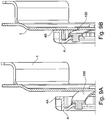
- FIGS. 9A can be removed, the drive ring according to the axial mobility of the leaf springs 100 maximum in the direction of drive (in Figure 9A "far left”).
- the case achievable maximum distance is in Figure 9A recognizable as a distance between the collar 4A of the driver ring 4 and the motor-side contact surface of the driver ring.
- the Mitauerkranz like FIG. 9B removable "far right” are located. Then all tolerances at the corresponding lower limit and ZMS and double clutch would be pushed together the next. In this position, then the leaf spring is biased the farthest. Between these two positions 9A and 9B, all intermediate positions are conceivable.
- FIGS. 8 and FIGS. 9A and 9B show examples of individual leaf springs. However, this is only to be understood, so that from the teaching of the present invention, individual leaf springs, and leaf spring assemblies, as well as a plurality along the circumference (evenly) distributed leaf springs / leaf spring assemblies are included.
- the type of connection between the leaf springs / leaf spring assemblies and the respective components via riveted joints are alternatively executable differently, for example via screw.
- a maximum distance between the driver ring 4 and the driver ring 1 is further than the theoretical maximum distance between ZMS and double clutch is set, so that in this case a bias in the circumferential direction of the spline due to the axial displacement occurring during assembly and thereby conditional twisting of the driving ring can be adjusted.
- B is the toothing length of the drive ring over the execution of Fig. 1 to 7 significantly shortened.
- a collar At the end of the toothing is a collar. This serves as a stop for the ZMS-side toothing in the flange.
- the connection between the driving ring and driving ring is realized by an axially movable, resilient element, here represented for example by leaf springs which are stiff in the circumferential direction to transmit the torque.
- the drive ring can be leftmost ( Fig. 9A ). This would mean that all tolerances would be at the upper limit and thus ZMS and dual clutch would be furthest apart.
- the drive ring can be located on the far right ( Fig. 9B ). Then all tolerances at the lower limit and ZMS and Doppelkupplung would be pushed together the next. The leaf springs would be the most preloaded. All stepless positions in between are conceivable.
Landscapes
- Engineering & Computer Science (AREA)
- General Engineering & Computer Science (AREA)
- Mechanical Engineering (AREA)
- Physics & Mathematics (AREA)
- Acoustics & Sound (AREA)
- Aviation & Aerospace Engineering (AREA)
- Mechanical Operated Clutches (AREA)
Claims (2)
- Dispositif de transfert de couple comprenant un raccord enfichable (10, 10a) entre un premier module et un deuxième module, ou entre un amortisseur d'oscillations de torsion et un embrayage, et comprenant une couronne dentée, une denture étant réalisée sur l'un des deux modules, et la couronne dentée (3, 3a) s'engageant dans la denture étant reliée de manière élastique et déplaçable axialement à l'autre, respectif, des deux modules, une liaison à ressort à lame étant prévue en tant que liaison élastique et déplaçable axialement entre la couronne dentée (3, 3a) et l'autre, respectif, des modules, de telle sorte que le couple soit transmis du premier module au deuxième module par le biais de la liaison à ressort à lame, caractérisé en ce que le premier module est une bride du côté secondaire d'un volant bimasse (ZMS) et le deuxième module est une bague d'entraînement (1), la couronne dentée est réalisée sous forme de couronne d'entraînement (4) et la couronne d'entraînement (4) est reliée à la bague d'entraînement (1) par le biais de ressorts à lame (100) de telle sorte que la couronne d'entraînement (4) soit accrochée axialement de manière déplaçable du côté de l'embrayage à la bague d'entraînement (1).
- Dispositif de transfert de couple (10) selon l'une quelconque des revendications 1 ou 2, dans lequel la liaison à ressort à lame comprend au moins un ressort à lame ou un paquet de ressorts à lames, de préférence toutefois plusieurs ressorts à lames ou plusieurs paquets de ressorts à lames disposés de manière répartie le long de la périphérie de la couronne dentée.
Applications Claiming Priority (2)
| Application Number | Priority Date | Filing Date | Title |
|---|---|---|---|
| DE102011105682 | 2011-06-22 | ||
| PCT/DE2012/000585 WO2012175065A1 (fr) | 2011-06-22 | 2012-06-04 | Dispositif de transmission d'un couple |
Publications (2)
| Publication Number | Publication Date |
|---|---|
| EP2724041A1 EP2724041A1 (fr) | 2014-04-30 |
| EP2724041B1 true EP2724041B1 (fr) | 2018-08-08 |
Family
ID=46507825
Family Applications (1)
| Application Number | Title | Priority Date | Filing Date |
|---|---|---|---|
| EP12734784.7A Not-in-force EP2724041B1 (fr) | 2011-06-22 | 2012-06-04 | Dispositif de transmission d'un couple |
Country Status (4)
| Country | Link |
|---|---|
| EP (1) | EP2724041B1 (fr) |
| CN (1) | CN103547824A (fr) |
| DE (1) | DE102012209344A1 (fr) |
| WO (1) | WO2012175065A1 (fr) |
Families Citing this family (4)
| Publication number | Priority date | Publication date | Assignee | Title |
|---|---|---|---|---|
| US9382968B2 (en) * | 2014-01-14 | 2016-07-05 | Electro-Motive Diesel, Inc. | Engine system having torsional coupling with thin web flywheel |
| US9291210B2 (en) * | 2014-08-11 | 2016-03-22 | GM Global Technology Operations LLC | Flywheel and dual clutch module assembly |
| DE102015203943A1 (de) * | 2015-03-05 | 2016-09-08 | Schaeffler Technologies AG & Co. KG | Tilger zur Verringerung einer Drehungleichförmigkeit |
| CN111609048B (zh) * | 2020-06-02 | 2021-11-16 | 浙江华信汽车零部件有限公司 | 一种可调式离合器盖总成 |
Citations (2)
| Publication number | Priority date | Publication date | Assignee | Title |
|---|---|---|---|---|
| EP1617096A2 (fr) * | 2004-07-16 | 2006-01-18 | Zf Friedrichshafen Ag | Dispositif de transmission de couple entre les composants dans une transmission d'un véhicule automobile |
| DE102006019977A1 (de) * | 2005-05-19 | 2006-11-23 | Luk Lamellen Und Kupplungsbau Beteiligungs Kg | Drehmomentübertragungseinrichtung |
Family Cites Families (8)
| Publication number | Priority date | Publication date | Assignee | Title |
|---|---|---|---|---|
| EP1632687B1 (fr) * | 2004-09-03 | 2008-11-26 | LuK Lamellen und Kupplungsbau Beteiligungs KG | Dispositif de transmission de couple |
| DE102005037514B4 (de) | 2004-09-03 | 2021-09-30 | Schaeffler Technologies AG & Co. KG | Drehmomentübertragungseinrichtung |
| EP1731786A3 (fr) * | 2005-06-09 | 2007-05-02 | LuK Lamellen und Kupplungsbau Beteiligungs KG | Disque d'embrayage |
| DE102005045158A1 (de) * | 2005-09-21 | 2007-03-22 | Zf Friedrichshafen Ag | Doppel-Kupplungseinrichtung und Axial-Abstützungseinrichtung hierfür |
| DE102007004203A1 (de) * | 2007-01-27 | 2008-07-31 | Zf Friedrichshafen Ag | Antriebssystem für ein Fahrzeug |
| EP2012034A3 (fr) | 2007-07-02 | 2010-10-20 | LuK Lamellen und Kupplungsbau Beteiligungs KG | Ensemble embrayage |
| DE102008032273B4 (de) * | 2008-02-18 | 2021-12-23 | Borgwarner Inc. | Kupplungseinrichtung mit einer Flexplatte |
| WO2012069028A1 (fr) * | 2010-11-24 | 2012-05-31 | Schaeffler Technologies AG & Co. KG | Dispositif de serrage pour un accouplement arbre-moyeu |
-
2012
- 2012-06-04 DE DE102012209344A patent/DE102012209344A1/de not_active Withdrawn
- 2012-06-04 EP EP12734784.7A patent/EP2724041B1/fr not_active Not-in-force
- 2012-06-04 WO PCT/DE2012/000585 patent/WO2012175065A1/fr not_active Ceased
- 2012-06-04 CN CN201280024968.7A patent/CN103547824A/zh active Pending
Patent Citations (2)
| Publication number | Priority date | Publication date | Assignee | Title |
|---|---|---|---|---|
| EP1617096A2 (fr) * | 2004-07-16 | 2006-01-18 | Zf Friedrichshafen Ag | Dispositif de transmission de couple entre les composants dans une transmission d'un véhicule automobile |
| DE102006019977A1 (de) * | 2005-05-19 | 2006-11-23 | Luk Lamellen Und Kupplungsbau Beteiligungs Kg | Drehmomentübertragungseinrichtung |
Also Published As
| Publication number | Publication date |
|---|---|
| DE102012209344A1 (de) | 2012-12-27 |
| CN103547824A (zh) | 2014-01-29 |
| WO2012175065A1 (fr) | 2012-12-27 |
| EP2724041A1 (fr) | 2014-04-30 |
Similar Documents
| Publication | Publication Date | Title |
|---|---|---|
| EP3093516B1 (fr) | Systeme de serrage pour une chaine cinematique d'un vehicule automobile | |
| EP1902226A2 (fr) | Unite d'accouplement | |
| WO2008046379A1 (fr) | Ensemble d'embrayage | |
| DE102011102117A1 (de) | Verspanneinrichtung für eine Welle-Nabe-Verbindung | |
| DE102012221653A1 (de) | Nasskupplung | |
| EP1862689A1 (fr) | Agencement de transmission d'un couple de rotation pour le conducteur de commande d'un véhicule | |
| WO2021043364A1 (fr) | Unité d'entraînement conçue pour une chaîne cinématique hybride | |
| EP2724041B1 (fr) | Dispositif de transmission d'un couple | |
| DE102021104113A1 (de) | Drehmomentübertragungseinrichtung, insbesondere für einen Antriebsstrang eines Kraftfahrzeugs | |
| DE102010022916A1 (de) | Drehmomentübertragungseinrichtung | |
| DE102013215582A1 (de) | Drehmomentübertragungseinrichtung und Steckverbindung für diese | |
| DE102018110076A1 (de) | Welle-Nabe-Verbindung, insbesondere für einen Drehschwingungsdämpfer und Drehschwingungsdämpfer mit einem Nabenteil dieser | |
| DE102017114444A1 (de) | Tilgereinrichtung | |
| DE102010050462A1 (de) | Steckverzahnung in einem Kupplungsaggregat | |
| WO2018177468A1 (fr) | Liaison arbre-moyeu avec élément de calage pour dentures d'emboîtement ainsi que chaîne cinématique | |
| DE19810297A1 (de) | Verbindungseinrichtung zum Herstellen einer Drehmomentübertragungsverbindung zwischen einem Drehmomentwandler und einer Antriebswelle | |
| DE102013206675A1 (de) | Antriebsstrangbaukasten für Kraftfahrzeuge | |
| DE102010032658A1 (de) | Drehmomentübertragungseinrichtung | |
| EP1979648A1 (fr) | Dispositif de transmission de couple de rotation | |
| EP2516872B1 (fr) | Dispositif à connexion à fiches | |
| DE102005049433A1 (de) | Axiale Steckverbindungsanordnung | |
| EP1657472B1 (fr) | Connexion enfichable axiale | |
| DE102015212896A1 (de) | Nabenteil für eine Steckverzahnung | |
| DE102021213313A1 (de) | Welle-Nabe-Verbindung | |
| DE102019130273A1 (de) | Drehmomentübertragungseinrichtung |
Legal Events
| Date | Code | Title | Description |
|---|---|---|---|
| PUAI | Public reference made under article 153(3) epc to a published international application that has entered the european phase |
Free format text: ORIGINAL CODE: 0009012 |
|
| 17P | Request for examination filed |
Effective date: 20140122 |
|
| AK | Designated contracting states |
Kind code of ref document: A1 Designated state(s): AL AT BE BG CH CY CZ DE DK EE ES FI FR GB GR HR HU IE IS IT LI LT LU LV MC MK MT NL NO PL PT RO RS SE SI SK SM TR |
|
| DAX | Request for extension of the european patent (deleted) | ||
| RAP1 | Party data changed (applicant data changed or rights of an application transferred) |
Owner name: SCHAEFFLER TECHNOLOGIES AG & CO. KG |
|
| STAA | Information on the status of an ep patent application or granted ep patent |
Free format text: STATUS: EXAMINATION IS IN PROGRESS |
|
| 17Q | First examination report despatched |
Effective date: 20161123 |
|
| GRAP | Despatch of communication of intention to grant a patent |
Free format text: ORIGINAL CODE: EPIDOSNIGR1 |
|
| STAA | Information on the status of an ep patent application or granted ep patent |
Free format text: STATUS: GRANT OF PATENT IS INTENDED |
|
| INTG | Intention to grant announced |
Effective date: 20180117 |
|
| GRAS | Grant fee paid |
Free format text: ORIGINAL CODE: EPIDOSNIGR3 |
|
| GRAA | (expected) grant |
Free format text: ORIGINAL CODE: 0009210 |
|
| STAA | Information on the status of an ep patent application or granted ep patent |
Free format text: STATUS: THE PATENT HAS BEEN GRANTED |
|
| AK | Designated contracting states |
Kind code of ref document: B1 Designated state(s): AL AT BE BG CH CY CZ DE DK EE ES FI FR GB GR HR HU IE IS IT LI LT LU LV MC MK MT NL NO PL PT RO RS SE SI SK SM TR |
|
| REG | Reference to a national code |
Ref country code: GB Ref legal event code: FG4D Free format text: NOT ENGLISH |
|
| REG | Reference to a national code |
Ref country code: CH Ref legal event code: EP Ref country code: AT Ref legal event code: REF Ref document number: 1027360 Country of ref document: AT Kind code of ref document: T Effective date: 20180815 |
|
| REG | Reference to a national code |
Ref country code: IE Ref legal event code: FG4D Free format text: LANGUAGE OF EP DOCUMENT: GERMAN |
|
| REG | Reference to a national code |
Ref country code: DE Ref legal event code: R096 Ref document number: 502012013213 Country of ref document: DE |
|
| REG | Reference to a national code |
Ref country code: NL Ref legal event code: MP Effective date: 20180808 |
|
| REG | Reference to a national code |
Ref country code: LT Ref legal event code: MG4D |
|
| PG25 | Lapsed in a contracting state [announced via postgrant information from national office to epo] |
Ref country code: NO Free format text: LAPSE BECAUSE OF FAILURE TO SUBMIT A TRANSLATION OF THE DESCRIPTION OR TO PAY THE FEE WITHIN THE PRESCRIBED TIME-LIMIT Effective date: 20181108 Ref country code: SE Free format text: LAPSE BECAUSE OF FAILURE TO SUBMIT A TRANSLATION OF THE DESCRIPTION OR TO PAY THE FEE WITHIN THE PRESCRIBED TIME-LIMIT Effective date: 20180808 Ref country code: GR Free format text: LAPSE BECAUSE OF FAILURE TO SUBMIT A TRANSLATION OF THE DESCRIPTION OR TO PAY THE FEE WITHIN THE PRESCRIBED TIME-LIMIT Effective date: 20181109 Ref country code: FI Free format text: LAPSE BECAUSE OF FAILURE TO SUBMIT A TRANSLATION OF THE DESCRIPTION OR TO PAY THE FEE WITHIN THE PRESCRIBED TIME-LIMIT Effective date: 20180808 Ref country code: LT Free format text: LAPSE BECAUSE OF FAILURE TO SUBMIT A TRANSLATION OF THE DESCRIPTION OR TO PAY THE FEE WITHIN THE PRESCRIBED TIME-LIMIT Effective date: 20180808 Ref country code: RS Free format text: LAPSE BECAUSE OF FAILURE TO SUBMIT A TRANSLATION OF THE DESCRIPTION OR TO PAY THE FEE WITHIN THE PRESCRIBED TIME-LIMIT Effective date: 20180808 Ref country code: PL Free format text: LAPSE BECAUSE OF FAILURE TO SUBMIT A TRANSLATION OF THE DESCRIPTION OR TO PAY THE FEE WITHIN THE PRESCRIBED TIME-LIMIT Effective date: 20180808 Ref country code: IS Free format text: LAPSE BECAUSE OF FAILURE TO SUBMIT A TRANSLATION OF THE DESCRIPTION OR TO PAY THE FEE WITHIN THE PRESCRIBED TIME-LIMIT Effective date: 20181208 Ref country code: BG Free format text: LAPSE BECAUSE OF FAILURE TO SUBMIT A TRANSLATION OF THE DESCRIPTION OR TO PAY THE FEE WITHIN THE PRESCRIBED TIME-LIMIT Effective date: 20181108 Ref country code: NL Free format text: LAPSE BECAUSE OF FAILURE TO SUBMIT A TRANSLATION OF THE DESCRIPTION OR TO PAY THE FEE WITHIN THE PRESCRIBED TIME-LIMIT Effective date: 20180808 |
|
| PG25 | Lapsed in a contracting state [announced via postgrant information from national office to epo] |
Ref country code: AL Free format text: LAPSE BECAUSE OF FAILURE TO SUBMIT A TRANSLATION OF THE DESCRIPTION OR TO PAY THE FEE WITHIN THE PRESCRIBED TIME-LIMIT Effective date: 20180808 Ref country code: LV Free format text: LAPSE BECAUSE OF FAILURE TO SUBMIT A TRANSLATION OF THE DESCRIPTION OR TO PAY THE FEE WITHIN THE PRESCRIBED TIME-LIMIT Effective date: 20180808 Ref country code: HR Free format text: LAPSE BECAUSE OF FAILURE TO SUBMIT A TRANSLATION OF THE DESCRIPTION OR TO PAY THE FEE WITHIN THE PRESCRIBED TIME-LIMIT Effective date: 20180808 |
|
| PG25 | Lapsed in a contracting state [announced via postgrant information from national office to epo] |
Ref country code: EE Free format text: LAPSE BECAUSE OF FAILURE TO SUBMIT A TRANSLATION OF THE DESCRIPTION OR TO PAY THE FEE WITHIN THE PRESCRIBED TIME-LIMIT Effective date: 20180808 Ref country code: ES Free format text: LAPSE BECAUSE OF FAILURE TO SUBMIT A TRANSLATION OF THE DESCRIPTION OR TO PAY THE FEE WITHIN THE PRESCRIBED TIME-LIMIT Effective date: 20180808 Ref country code: CZ Free format text: LAPSE BECAUSE OF FAILURE TO SUBMIT A TRANSLATION OF THE DESCRIPTION OR TO PAY THE FEE WITHIN THE PRESCRIBED TIME-LIMIT Effective date: 20180808 Ref country code: IT Free format text: LAPSE BECAUSE OF FAILURE TO SUBMIT A TRANSLATION OF THE DESCRIPTION OR TO PAY THE FEE WITHIN THE PRESCRIBED TIME-LIMIT Effective date: 20180808 Ref country code: RO Free format text: LAPSE BECAUSE OF FAILURE TO SUBMIT A TRANSLATION OF THE DESCRIPTION OR TO PAY THE FEE WITHIN THE PRESCRIBED TIME-LIMIT Effective date: 20180808 |
|
| REG | Reference to a national code |
Ref country code: DE Ref legal event code: R097 Ref document number: 502012013213 Country of ref document: DE |
|
| PG25 | Lapsed in a contracting state [announced via postgrant information from national office to epo] |
Ref country code: SM Free format text: LAPSE BECAUSE OF FAILURE TO SUBMIT A TRANSLATION OF THE DESCRIPTION OR TO PAY THE FEE WITHIN THE PRESCRIBED TIME-LIMIT Effective date: 20180808 Ref country code: DK Free format text: LAPSE BECAUSE OF FAILURE TO SUBMIT A TRANSLATION OF THE DESCRIPTION OR TO PAY THE FEE WITHIN THE PRESCRIBED TIME-LIMIT Effective date: 20180808 Ref country code: SK Free format text: LAPSE BECAUSE OF FAILURE TO SUBMIT A TRANSLATION OF THE DESCRIPTION OR TO PAY THE FEE WITHIN THE PRESCRIBED TIME-LIMIT Effective date: 20180808 |
|
| PLBE | No opposition filed within time limit |
Free format text: ORIGINAL CODE: 0009261 |
|
| STAA | Information on the status of an ep patent application or granted ep patent |
Free format text: STATUS: NO OPPOSITION FILED WITHIN TIME LIMIT |
|
| 26N | No opposition filed |
Effective date: 20190509 |
|
| PG25 | Lapsed in a contracting state [announced via postgrant information from national office to epo] |
Ref country code: SI Free format text: LAPSE BECAUSE OF FAILURE TO SUBMIT A TRANSLATION OF THE DESCRIPTION OR TO PAY THE FEE WITHIN THE PRESCRIBED TIME-LIMIT Effective date: 20180808 |
|
| PG25 | Lapsed in a contracting state [announced via postgrant information from national office to epo] |
Ref country code: MC Free format text: LAPSE BECAUSE OF FAILURE TO SUBMIT A TRANSLATION OF THE DESCRIPTION OR TO PAY THE FEE WITHIN THE PRESCRIBED TIME-LIMIT Effective date: 20180808 |
|
| REG | Reference to a national code |
Ref country code: CH Ref legal event code: PL |
|
| GBPC | Gb: european patent ceased through non-payment of renewal fee |
Effective date: 20190604 |
|
| REG | Reference to a national code |
Ref country code: BE Ref legal event code: MM Effective date: 20190630 |
|
| PG25 | Lapsed in a contracting state [announced via postgrant information from national office to epo] |
Ref country code: TR Free format text: LAPSE BECAUSE OF FAILURE TO SUBMIT A TRANSLATION OF THE DESCRIPTION OR TO PAY THE FEE WITHIN THE PRESCRIBED TIME-LIMIT Effective date: 20180808 |
|
| PG25 | Lapsed in a contracting state [announced via postgrant information from national office to epo] |
Ref country code: IE Free format text: LAPSE BECAUSE OF NON-PAYMENT OF DUE FEES Effective date: 20190604 Ref country code: GB Free format text: LAPSE BECAUSE OF NON-PAYMENT OF DUE FEES Effective date: 20190604 |
|
| PG25 | Lapsed in a contracting state [announced via postgrant information from national office to epo] |
Ref country code: LI Free format text: LAPSE BECAUSE OF NON-PAYMENT OF DUE FEES Effective date: 20190630 Ref country code: BE Free format text: LAPSE BECAUSE OF NON-PAYMENT OF DUE FEES Effective date: 20190630 Ref country code: LU Free format text: LAPSE BECAUSE OF NON-PAYMENT OF DUE FEES Effective date: 20190604 Ref country code: CH Free format text: LAPSE BECAUSE OF NON-PAYMENT OF DUE FEES Effective date: 20190630 |
|
| PG25 | Lapsed in a contracting state [announced via postgrant information from national office to epo] |
Ref country code: PT Free format text: LAPSE BECAUSE OF FAILURE TO SUBMIT A TRANSLATION OF THE DESCRIPTION OR TO PAY THE FEE WITHIN THE PRESCRIBED TIME-LIMIT Effective date: 20181208 |
|
| REG | Reference to a national code |
Ref country code: AT Ref legal event code: MM01 Ref document number: 1027360 Country of ref document: AT Kind code of ref document: T Effective date: 20190604 |
|
| PG25 | Lapsed in a contracting state [announced via postgrant information from national office to epo] |
Ref country code: AT Free format text: LAPSE BECAUSE OF NON-PAYMENT OF DUE FEES Effective date: 20190604 |
|
| PG25 | Lapsed in a contracting state [announced via postgrant information from national office to epo] |
Ref country code: CY Free format text: LAPSE BECAUSE OF FAILURE TO SUBMIT A TRANSLATION OF THE DESCRIPTION OR TO PAY THE FEE WITHIN THE PRESCRIBED TIME-LIMIT Effective date: 20180808 |
|
| PG25 | Lapsed in a contracting state [announced via postgrant information from national office to epo] |
Ref country code: MT Free format text: LAPSE BECAUSE OF FAILURE TO SUBMIT A TRANSLATION OF THE DESCRIPTION OR TO PAY THE FEE WITHIN THE PRESCRIBED TIME-LIMIT Effective date: 20180808 Ref country code: HU Free format text: LAPSE BECAUSE OF FAILURE TO SUBMIT A TRANSLATION OF THE DESCRIPTION OR TO PAY THE FEE WITHIN THE PRESCRIBED TIME-LIMIT; INVALID AB INITIO Effective date: 20120604 |
|
| PGFP | Annual fee paid to national office [announced via postgrant information from national office to epo] |
Ref country code: FR Payment date: 20210622 Year of fee payment: 10 |
|
| PGFP | Annual fee paid to national office [announced via postgrant information from national office to epo] |
Ref country code: DE Payment date: 20210819 Year of fee payment: 10 |
|
| PG25 | Lapsed in a contracting state [announced via postgrant information from national office to epo] |
Ref country code: MK Free format text: LAPSE BECAUSE OF FAILURE TO SUBMIT A TRANSLATION OF THE DESCRIPTION OR TO PAY THE FEE WITHIN THE PRESCRIBED TIME-LIMIT Effective date: 20180808 |
|
| REG | Reference to a national code |
Ref country code: DE Ref legal event code: R119 Ref document number: 502012013213 Country of ref document: DE |
|
| PG25 | Lapsed in a contracting state [announced via postgrant information from national office to epo] |
Ref country code: FR Free format text: LAPSE BECAUSE OF NON-PAYMENT OF DUE FEES Effective date: 20220630 |
|
| PG25 | Lapsed in a contracting state [announced via postgrant information from national office to epo] |
Ref country code: DE Free format text: LAPSE BECAUSE OF NON-PAYMENT OF DUE FEES Effective date: 20230103 |
|
| P01 | Opt-out of the competence of the unified patent court (upc) registered |
Effective date: 20230522 |