EP2724059B1 - Actionneur destiné à un véhicule automobile et procédé - Google Patents
Actionneur destiné à un véhicule automobile et procédé Download PDFInfo
- Publication number
- EP2724059B1 EP2724059B1 EP12727241.7A EP12727241A EP2724059B1 EP 2724059 B1 EP2724059 B1 EP 2724059B1 EP 12727241 A EP12727241 A EP 12727241A EP 2724059 B1 EP2724059 B1 EP 2724059B1
- Authority
- EP
- European Patent Office
- Prior art keywords
- housing
- locking bolt
- actuating drive
- spindle
- carriage
- Prior art date
- Legal status (The legal status is an assumption and is not a legal conclusion. Google has not performed a legal analysis and makes no representation as to the accuracy of the status listed.)
- Active
Links
Images



Classifications
-
- H—ELECTRICITY
- H02—GENERATION; CONVERSION OR DISTRIBUTION OF ELECTRIC POWER
- H02K—DYNAMO-ELECTRIC MACHINES
- H02K5/00—Casings; Enclosures; Supports
- H02K5/04—Casings or enclosures characterised by the shape, form or construction thereof
- H02K5/10—Casings or enclosures characterised by the shape, form or construction thereof with arrangements for protection from ingress, e.g. water or fingers
-
- B—PERFORMING OPERATIONS; TRANSPORTING
- B60—VEHICLES IN GENERAL
- B60K—ARRANGEMENT OR MOUNTING OF PROPULSION UNITS OR OF TRANSMISSIONS IN VEHICLES; ARRANGEMENT OR MOUNTING OF PLURAL DIVERSE PRIME-MOVERS IN VEHICLES; AUXILIARY DRIVES FOR VEHICLES; INSTRUMENTATION OR DASHBOARDS FOR VEHICLES; ARRANGEMENTS IN CONNECTION WITH COOLING, AIR INTAKE, GAS EXHAUST OR FUEL SUPPLY OF PROPULSION UNITS IN VEHICLES
- B60K15/00—Arrangement in connection with fuel supply of combustion engines or other fuel consuming energy converters, e.g. fuel cells; Mounting or construction of fuel tanks
- B60K15/03—Fuel tanks
- B60K15/04—Tank inlets
- B60K15/05—Inlet covers
-
- E—FIXED CONSTRUCTIONS
- E05—LOCKS; KEYS; WINDOW OR DOOR FITTINGS; SAFES
- E05B—LOCKS; ACCESSORIES THEREFOR; HANDCUFFS
- E05B77/00—Vehicle locks characterised by special functions or purposes
- E05B77/34—Protection against weather or dirt, e.g. against water ingress
-
- E—FIXED CONSTRUCTIONS
- E05—LOCKS; KEYS; WINDOW OR DOOR FITTINGS; SAFES
- E05B—LOCKS; ACCESSORIES THEREFOR; HANDCUFFS
- E05B81/00—Power-actuated vehicle locks
- E05B81/02—Power-actuated vehicle locks characterised by the type of actuators used
- E05B81/04—Electrical
- E05B81/06—Electrical using rotary motors
-
- E—FIXED CONSTRUCTIONS
- E05—LOCKS; KEYS; WINDOW OR DOOR FITTINGS; SAFES
- E05B—LOCKS; ACCESSORIES THEREFOR; HANDCUFFS
- E05B81/00—Power-actuated vehicle locks
- E05B81/12—Power-actuated vehicle locks characterised by the function or purpose of the powered actuators
- E05B81/18—Power-actuated vehicle locks characterised by the function or purpose of the powered actuators to effect movement of a bolt or bolts
-
- E—FIXED CONSTRUCTIONS
- E05—LOCKS; KEYS; WINDOW OR DOOR FITTINGS; SAFES
- E05B—LOCKS; ACCESSORIES THEREFOR; HANDCUFFS
- E05B81/00—Power-actuated vehicle locks
- E05B81/24—Power-actuated vehicle locks characterised by constructional features of the actuator or the power transmission
- E05B81/32—Details of the actuator transmission
- E05B81/34—Details of the actuator transmission of geared transmissions
-
- E—FIXED CONSTRUCTIONS
- E05—LOCKS; KEYS; WINDOW OR DOOR FITTINGS; SAFES
- E05B—LOCKS; ACCESSORIES THEREFOR; HANDCUFFS
- E05B81/00—Power-actuated vehicle locks
- E05B81/24—Power-actuated vehicle locks characterised by constructional features of the actuator or the power transmission
- E05B81/32—Details of the actuator transmission
- E05B81/40—Nuts or nut-like elements moving along a driven threaded axle
-
- E—FIXED CONSTRUCTIONS
- E05—LOCKS; KEYS; WINDOW OR DOOR FITTINGS; SAFES
- E05B—LOCKS; ACCESSORIES THEREFOR; HANDCUFFS
- E05B83/00—Vehicle locks specially adapted for particular types of wing or vehicle
- E05B83/28—Locks for glove compartments, console boxes, fuel inlet covers or the like
- E05B83/32—Locks for glove compartments, console boxes, fuel inlet covers or the like for console boxes, e.g. between passenger seats
-
- E—FIXED CONSTRUCTIONS
- E05—LOCKS; KEYS; WINDOW OR DOOR FITTINGS; SAFES
- E05B—LOCKS; ACCESSORIES THEREFOR; HANDCUFFS
- E05B85/00—Details of vehicle locks not provided for in groups E05B77/00 - E05B83/00
- E05B85/02—Lock casings
-
- F—MECHANICAL ENGINEERING; LIGHTING; HEATING; WEAPONS; BLASTING
- F16—ENGINEERING ELEMENTS AND UNITS; GENERAL MEASURES FOR PRODUCING AND MAINTAINING EFFECTIVE FUNCTIONING OF MACHINES OR INSTALLATIONS; THERMAL INSULATION IN GENERAL
- F16J—PISTONS; CYLINDERS; SEALINGS
- F16J15/00—Sealings
- F16J15/16—Sealings between relatively-moving surfaces
- F16J15/32—Sealings between relatively-moving surfaces with elastic sealings, e.g. O-rings
- F16J15/3204—Sealings between relatively-moving surfaces with elastic sealings, e.g. O-rings with at least one lip
- F16J15/3232—Sealings between relatively-moving surfaces with elastic sealings, e.g. O-rings with at least one lip having two or more lips
-
- H—ELECTRICITY
- H02—GENERATION; CONVERSION OR DISTRIBUTION OF ELECTRIC POWER
- H02K—DYNAMO-ELECTRIC MACHINES
- H02K7/00—Arrangements for handling mechanical energy structurally associated with dynamo-electric machines, e.g. structural association with mechanical driving motors or auxiliary dynamo-electric machines
- H02K7/06—Means for converting reciprocating motion into rotary motion or vice versa
Definitions
- the invention relates to an actuator preferably for a motor vehicle having the features of the preamble of claim 1 and an assembly method.
- the generic document DE 102 59 465 A1 discloses an actuator for a fuel tank flap lock of a motor vehicle with an electric motor, which is able to rotate a spindle. A rotational movement of the spindle causes a linear displacement of a bolt. The latch is sealed to the outside by a bellows to protect the actuator from moisture and dirt.
- the publication DE 102 14 398 A1 discloses an actuator with a shape memory element.
- German patent application 10 2010 003 523.8 goes a locking device with an actuator, ie an actuator with a bolt out, the actuator is mounted on a housing wall of a first component.
- a second component has a second housing wall.
- the housing wall of the second component is pushed into an opening in the housing wall of the first component.
- the latch of the actuator is pushed through a hole of the housing wall of the first component and further into a hole or in a recess of the adjacent housing wall of the second component, so as to lock the two components together.
- an actuator has to cope with many different requirements, since a motor vehicle usually does not allow a large amount of space, very different exposed to climatic conditions and is mechanically stressed by shocks and accelerations.
- an actuator comprises the features of the first claim and / or the features according to one or more additional claims.
- Advantageous embodiments emerge from the subclaims.
- the actuator according to claim 1 has a latch which can be moved back and forth between two different positions, and in principle at least partially out of a sealed housing of the actuator and into it.
- the bolt is in particular at least substantially pin-shaped, bolt-shaped or cylindrical.
- One end of the latch that can be moved out of the housing may be ramped to push the latch back toward the housing using the ramp, as is known from a door latch latch.
- the latch may be moved against a spring force of a biased spring toward the housing.
- the bolt can at least partially be moved out of the housing again.
- the actuator can also perform alternatively or additionally a rotary motion to be moved from one position to another position.
- the actuator includes a drive with which the bolt can be moved. It is in particular an electric drive, which includes, for example, an electric motor or a drive based on a shape memory alloy.
- the aforementioned, optionally provided spring may also be provided as a drive.
- the actuator comprises a deformable material ring seal, through which the bolt is passed.
- the material of the ring seal behaves in particular elastic. It is therefore preferably an elastomer from which the ring seal is made.
- the ring seal helps seal the interior of the actuator housing outward to prevent dust or moisture from entering the interior of the housing.
- the ring seal has an X-shaped cross-section or at least with at least two band-shaped or linearly extending regions circumferentially on the bolt tight. Such a cross-section or such a close contact has been found to be particularly advantageous and in particular in comparison to conventional circular cross-sections of ring seals.
- the cross-section may also resemble a rectangle or a square.
- sides of the cross-section generally extend in an arcuate and / or angled manner inwards so that the cross-section is similar to an X.
- the entire cross section extends exclusively arcuate and thus has no bends. This ensures improved that the sealing ring can not be damaged by compression.
- the X-shaped cross section or the double dense contact increases the number of areas that contribute to the sealing. It is therefore achieved a particularly reliable sealing effect.
- the ring seal is in one embodiment within a double wall of the housing, for example in a compressed form. So it may be necessary to press the ring seal together to bring them between the two walls of the double wall can. Due to the X-shape of the cross section of the ring seal this is then band-shaped or linear on the adjacent walls of the double wall. On each wall there are then two areas of the sealing ring, the band or line-shaped and circumferentially and that generally abut annular tightly against the two walls of the double wall.
- said wall portion presses or pushes the ring seal in the direction of the bolt so that at the same time circumferential band-shaped or linear regions of the ring seal are pressed against adjacent walls of a double wall of the housing and so further contribute to a sealing effect.
- the inner diameter of the ring seal in one embodiment is smaller than the outer diameter of the bolt and in such a way that the ring seal pressed against the bolt rests when the bolt passes through the ring seal.
- the latch is passed in one embodiment through an opening of the housing, which is formed by a one-piece wall portion of the housing. Due to the one-piece construction, the occurrence of a leak in the particularly critical region of the bolt leadthrough is particularly reliably avoided. To achieve this effect, it is not necessary for the ring seal to have an X - shaped cross section and / or to tightly abut the bar with at least two band - shaped or line - shaped areas, so as to prevent dust or moisture from entering the interior of the housing Actuator can get.
- the housing of the actuator is formed by two housing shells, which are connected together by means of a circumferential seal.
- the circumferential seal may be inserted in a circumferential groove of a housing shell or injected into such a circumferential groove.
- the two housing shells can be tightly connected to one another, for example by screw connections or rivet connections, thus forming a sealed housing into which no dust or moisture can penetrate.
- a generic actuator has, in one embodiment, a further annular seal which rests with its inner diameter on two housing shells of the housing and which is guided around an opening through which the bolt extends through.
- the further annular seal can serve to provide a sealed connection to another component to which the actuator is mounted, such as in the German patent application 10 2010 003 523.8 described way.
- the further annular seal ensures that the two housing shells are improved and held together, specifically in the particularly critical region which serves to pass the bolt and which is therefore particularly mechanically stressed.
- the further annular seal bears against the wall region which presses or presses the first-mentioned ring seal adjacent to the bolt in the direction of the bolt.
- the additional ring seal then contributes to the fact that the ring seal adjacent to the bolt seals particularly reliably. In order to achieve this effect, it is not necessary for the ring seal, which bears against the bolt, to have an X-shaped cross-section and / or to bear tightly against the bolt with at least two band-shaped or line-shaped regions.
- the further annular seal is preferably applied to a wall region of the housing which preferably protrudes perpendicularly from the wall region, which is guided around the opening for the bolt around. If the actuator is pressed against the wall of another component such as in the German patent application 10 2010 003 523.8 described way, so is the further ring seal between the protruding wall portion and the wall of the other component and thus contributes to a tight connection to the wall of the other component. The further ring seal then lies tightly and circumferentially against the protruding wall region and tight against the wall of the further component. Then no moisture or dust can get between these two wall areas. The protection against moisture or pollution is thus further improved.
- the further annular seal preferably has, in the non-tensioned state, a smaller inner diameter in comparison to the diameter of the wall against which the inner diameter of the further annular seal rests.
- the further annular seal is thus biased by stretching when it has been mounted and thus exerts a pressure in the direction of the wall, against which the inner diameter rests.
- This embodiment further supports improved that no dust or moisture can get into the interior of the actuator.
- the actuator has a connection device for connection to another component.
- a connection device for connection to another component.
- a bayonet connection device through which the bolt is passed.
- a threaded connection device may also be provided, for example in the form of an external thread through which the bolt is passed.
- a bayonet connection device is to be preferred, since such a connection can be made faster and, after the connection has been established, the affected components are aligned with one another in always the same, foreseeable manner.
- the space required for attachment to another component is minimized and, above all, both in the case of the bayonet connection device as well as in the case of the threaded connection device.
- it is not necessary for the ring seal to have an X-shaped cross-section and / or to bear tightly against the bolt at all times with at least two band-shaped or line-shaped regions.
- the actuator on a bolt which is connected by positive engagement with a carriage of the actuator.
- a bolt of an actuator expediently has various shapes, such as a ramp-shaped, movable out of the housing end in one case and a cylinder-shaped, movable out of the housing plan end in another case.
- this is preferably connected by positive engagement with a carriage.
- the individually manufactured component, so the bolt is on the one hand so small and on the other hand can be easily replaced.
- it is not necessary for the ring seal to have an X - shaped cross section and / or to be tightly abutting the bolt with at least two band - shaped or line - shaped regions.
- the positive connection between the carriage and the bolt is formed in one embodiment by a groove in the bolt and by a reaching into the groove wall portion of the carriage.
- the groove in particular extends annularly around the bolt.
- the reaching into the groove wall portion is preferably semicircular or U-shaped designed to be able to extend for a good grip particularly suitable in the groove and on the other hand to be able to be used in the groove without great technical effort.
- This embodiment allows a particularly simple assembly of bars and sledges and at the same time a long-lasting form-fitting connection between these two parts.
- a ring of elastic material is in the groove of the bolt and is held by this.
- the ring is pressed in particular against the reaching into the groove wall portion of the carriage. This ensures that the bolt is connected to the carriage without play or a game is at least minimized.
- the bolt can be moved accordingly precisely to desired positions.
- the actuator comprises in one embodiment a rotatably mounted spindle for moving the bolt and preferably at least two different bearings for the spindle.
- Two of the three bearings are then in an embodiment in front of and behind a drive wheel, which serves the drive of the spindle and is preferably integrally connected to this, in order to keep the number of parts used small.
- These two bearings preferably adjoin the drive wheel and / or an optionally provided spring cassette. Between such an adjacent storage and the drive wheel so still a spring cassette may be provided or at least a free space for such a spring cassette to rotate the spindle using a biased spring located in the cassette in one direction.
- a third bearing is in one embodiment at the end of the spindle, which points in the direction of bolt.
- the spindle usually causes a linear movement of the bolt.
- the spindle is then with its external thread by a corresponding internal thread of a rotatably mounted Carried slide, so as to achieve the desired movement.
- the slide is connected to the carriage. A rotation of the spindle shifts the carriage and thus the bar linear.
- At least one end of the spindle, preferably both ends of the spindle are rotatably supported by a bearing.
- a third bearing may be located between the two bearings, in particular to stabilize the position of a drive wheel. This embodiment also ensures a reliable long-term storage of the spindle.
- a bearing of the spindle forms in one embodiment a guide for a carriage and at the same time a stop for the carriage and / or the bolt, which is moved linearly by a rotation of the spindle.
- a bearing assumes at least a double function or even a triple function and thus contributes to the fact that the space of the actuator is low and the number of parts used is low.
- the aforementioned storage extends into an oblong hole of the carriage and thus ensures or at least contributes to the fact that the carriage is mounted non-rotatably and displaceably.
- the actuator is used in particular for locking a flap of a motor vehicle, such as the locking of a fuel filler flap or flap, which can cover a charging device of an electric vehicle.
- Serves the actuator of the lock of such a flap it preferably has a ramped end. If the flap is closed, so that the ramp-shaped end is mechanically pressed in the direction of the housing of the actuator and although preferred against a force of a preloaded spring. If the flap has reached its closed end position, then the bolt jumps back due to the prestressed spring in the starting position, which then the flap is locked. If the flap should be opened again, the bolt is moved back by a drive so in the direction of the housing of the actuator. It is in particular an electric drive.
- FIG. 1 shown a housing shell 1 of a housing of an actuator according to the invention.
- the housing shell 1 comprises a passage opening 2 through the housing shell 1 through for a in the FIG. 2 shown in section 3.
- the passage 2 is formed by a double wall 4, 5, which in the FIG. 2 is shown in section.
- the double wall 4,5 is open to one side. Through this open side is like in the FIG. 1 indicated a sealing ring 6 inserted.
- the sealing ring has an X-shape, which in the FIG. 2 is shown.
- the distance between the inner sides of the double wall 4.5 corresponds to the width of the sealing ring 6.
- the sealing ring 6 can therefore be at least largely frictionless and thus easily inserted between the walls 4 and 5 of the double wall, as shown in Figure 2 in section.
- FIG. 2 the dimensions of the sealing ring are shown in the compressed state. If the opening leading into the double wall is closed by a wall region 7 of a further housing shell, then the height of the space then available within the double wall 4, 5 is insufficient, as indicated by the dashed lines, to accommodate the sealing ring in the relaxed state therein, without squeezing him. Thus, if the opening leading into the double wall 4, 5 is closed by the wall region 7, then the wall region 7 presses the sealing ring 6 in the direction of the bolt 3, when it passes through the passage opening 2 passes through. In the same way, the wall portion 15 of the housing shell 1.
- the sealing ring 6 is thus pressed not only in the direction of bolt 3, but the X-shaped ends of the sealing ring are spread at the same time and pressed against the walls 4 and 5 of the double wall. If the sealing ring 6 pressed in this manner within the double wall 4, 5 held, so the sealing ring 6 provides a particularly reliable and durable for a watertight seal the particularly problematic passage area for the bolt 3.
- the X-shaped ends of the sealing ring 6 are then in pairs tight and circumferentially band-shaped or linearly on the bar 3, on the walls 4 and 5 and on the wall portions 7 and 15, which are opposite to the bolt 3. Through the opening 2 through then no water can get into the interior of the housing of the actuator and especially not even if the latch 3 is linearly displaced by a drive.
- the bolt 3 comprises a circumferential groove 9, in which an elastic ring 10 is held.
- the width of the elastic ring 10 is smaller than that Width of the groove 9, so that a wall portion of a carriage can get into the groove.
- the housing shell 1 which comprises a carriage 11, a spindle 12, a drive wheel 13 fixedly connected to the spindle 12, and optionally a spring cassette 14.
- the external thread of the spindle 12 is passed through a corresponding internal thread of the carriage 11 in order to convert a rotational movement of the spindle into a linear movement of the carriage 11 can.
- the spring cassette 14 includes a spring which can be further biased by rotating the drive wheel 13 or which is due to its bias in a position to rotate the drive wheel 13 in the opposite direction.
- the housing shell 1 further supports 16 and 17 for the rotatable mounting of the spindle 12. If the aforementioned assembly is inserted into the housing shell 1, the bearing 17 is adjacent from one side to the drive wheel 13 and the Bearing 16 from the other side to the spring cassette 14. In the bearing 8, the end of the spindle 12 is rotatably mounted, which faces the latch 3.
- the carriage 11 has two lateral boundaries 18 and 19 which abut laterally in the installed state on the stop 8 and thus cause a rotationally fixed mounting of the carriage 11.
- By the lateral boundaries 18 and 19 creates a kind of slot on the top of the carriage, in which the stop 8 as in the FIG. 5 shown extends when the aforementioned assembly is inserted into the housing shell 1.
- the carriage 11 has a U-shaped wall portion 20 which enters into the groove 9 of the bolt 3, when the aforementioned assembly is inserted into the housing shell 1 and the bolt 3 is in its mounting position.
- the existing elastic material ring 10 is compressed slightly by the insertion and thus ensures that the wall portion 20 is held without play in the groove 9 in the inserted state. This results in a form-fitting, play-free connection between the carriage 11 and the bolt. 3
- an electric motor 21 is used thereafter, which serves as an electric drive means.
- the housing shell 1 has bearings 22 and 23 and protruding electrical contacts 24 and 25 as in the FIGS. 1 . 3 . 4 and 5 shown on.
- the electrical contacts 24 and 25 and thus the electric motor 21 are supplied with power.
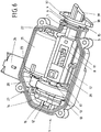
- the electric motor 21 comprises a shaft 27 with an associated drive roller 28, which may have a rubberized surface. If the electric motor 21 has been inserted into the housing shell 1, the drive roller 28 is frictionally engaged with the drive wheel 13, for example, as in FIG FIG. 6 will be shown. If the drive roller 28 is rotated by the electric motor 21, this rotational movement due to the frictional connection is transmitted to the drive wheel 13. The diameter of the drive roller 28 is small compared to the diameter of the drive wheel 13, so as to ensure a suitable translation. Instead of a frictional connection and a gear connection can be provided.
- a sensor such as a micro-switch can be used with which the position of the carriage 11 and thus the position of the bolt 3 can be detected.
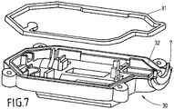
- a circumferential seal 31 is now in a groove 32 a in the FIG. 7 shown housing shell 30 used or injected.
- the housing shell 30 is now with the housing shell 1 as in the FIG. 8 shown connected and screwed by means of screws 33 as shown.
- screws 33 instead of screws 33 but other connection means may be provided, such as rivets or a clip connection with resilient, attached to a housing shell hook-shaped tabs that can engage in corresponding recesses in the other housing shell for a connection.
- FIG. 9 shows a bayonet connection with another component.
- the wings 37 and 38 of the bayonet connection are integrally connected to the housing shell 1.
- the wall portion 35 is also part of the integrally formed housing shell 1.
- the wall portion 36 is part of the integrally formed housing shell 30.
- the inner diameter of the further sealing ring 34 rests on the one hand on the wall portion 7 of the housing shell 30 and on the other hand on the wall portion 15 of the housing shell 1.
- the wall portions 35 and 36 are perpendicular from the wall portions 7 and 15.
- the further sealing ring 34 preferably has a relatively small diameter, so that this rests in the prestressed, stretched state with its inner diameter on the wall regions 7 and 15.
- the further, then stretched sealing ring 34 contributes to the fact that the wall portions 7 and 15 are not pressed apart by the compressed sealing ring 6 with the X-shaped cross section.
- the movable out of the actuator end 39 of the bolt 3 may be ramped, such as in the FIGS. 3, 4 . 5 . 6 . 8 and 9 will be shown. But it can also be provided a plan end 40, as in the FIG. 2 will be shown. Since the bolt 3 is relatively simple and built small, different bolt shapes can be provided and used depending on the desired application without great technical effort. Depending on the optionally optional components such as latch 3, sensor, spring cassette 14 or other sealing ring 34 actuators can be provided with different properties or for different applications, without having to operate a large technical effort.
- the assembly can be done almost without tools. If a locking connection is provided instead of a screw connection, then no tool is required for the assembly. Each assembly step is easy and without complicated handling to accomplish. The number of parts is very low. Therefore, the actuator can also be very small and light. The actuator is very reliable and permanently protected against the ingress of moisture or dust. By replacing individual, simply held components, the actuator can be adapted to different needs. Since the optional or optionally provided components are small, the storage space is correspondingly small, which is to be provided for the availability of different components.
Landscapes
- Engineering & Computer Science (AREA)
- Mechanical Engineering (AREA)
- General Engineering & Computer Science (AREA)
- Power Engineering (AREA)
- Sustainable Energy (AREA)
- Combustion & Propulsion (AREA)
- Transportation (AREA)
- Chemical & Material Sciences (AREA)
- Life Sciences & Earth Sciences (AREA)
- Sustainable Development (AREA)
- Transmission Devices (AREA)
- Power-Operated Mechanisms For Wings (AREA)
- Connection Of Motors, Electrical Generators, Mechanical Devices, And The Like (AREA)
Claims (17)
- Actionneur destiné à un véhicule automobile, comportant un boulon mobile (3) qui peut être déplacé au moins partiellement hors d'un boîtier étanche (1, 30) de l'actionneur et dans le boîtier (1, 30), comportant un entraînement (14, 21) pour déplacer le boulon (3), un joint annulaire (6) en matériau déformable à travers lequel le boulon (3) est passé, le boîtier (1, 30) de l'actionneur étant constitué de deux coquilles (1, 30) qui sont reliés l'un à l'autre de manière étanche au moyen d'un joint circonférentielle (31), caractérisé en ce que le joint annulaire (6) présente une section transversale en forme de X et/ou en ce qu'au moins deux zones en forme de bande ou linéaires du joint annulaire (6) sont en appui circonférentiellement contre le boulon (3), l'actionneur est disposé de telle sorte que le joint annulaire (6) est pressé ou serré par une zone de paroi (7) de l'une des coquilles de boîtier (30) dans la direction du boulon (3).
- Actionneur selon la revendication précédente, caractérisé en ce que le joint annulaire (6) est logé au sein d'une double paroi (4, 5) du boîtier (1, 30), et surtout sous forme comprimée.
- Actionneur selon l'une des revendications précédentes, caractérisé en ce que le diamètre intérieur du joint annulaire (6) est inférieur au diamètre extérieur adjacent du boulon (3).
- Actionneur selon l'une des revendications précédentes, caractérisé en ce que le boulon (3) est passé à travers une ouverture de passage (2) du boîtier (1, 30) qui est formée par une zone de paroi monobloc du boîtier (1, 30) et en particulier est relié d'un seul tenant à une coquille de boîtier (1) du boîtier (1, 30).
- Actionneur selon l'une des revendications précédentes, caractérisé par un autre joint annulaire (34) qui est en appui avec son diamètre intérieur contre deux coquilles de boîtier (1, 30) du boîtier et qui est passé autour d'une ouverture de passage (2) à travers laquelle le boulon (3) est passé.
- Actionneur selon l'une des revendications précédentes, caractérisé par un dispositif de liaison pour la liaison à un autre composant à travers lequel le boulon (3) est passé, en particulier un dispositif de liaison à baïonnette (37, 38).
- Actionneur selon l'une des revendications précédentes, caractérisé en ce que le boulon (3) est relié par engagement positif à un coulisseau (11) de l'actionneur.
- Actionneur selon la revendication précédente, caractérisé en ce que la liaison par engagement positif entre le coulisseau (11) et le boulon (3) est formée par une rainure (9) dans le boulon (3) et par une zone de paroi (20) du coulisseau (11) s'étendant dans la rainure (9).
- Actionneur selon la revendication précédente, caractérisé par un anneau (10) en matière déformable, en particulier en matière élastique ou plastique, qui est maintenue dans la rainure (9).
- Actionneur selon la revendication précédente, caractérisé en ce que l'anneau (10) est pressé contre la zone de paroi (20) du coulisseau qui s'étend dans la rainure (9).
- Actionneur selon l'une des revendications précédentes, caractérisé par une broche (12) montée rotative pour déplacer le boulon (3), avec au moins un palier pour la broche, de préférence avec trois paliers (8, 16, 17) pour la broche (12).
- Actionneur selon la revendication précédente, caractérisé en ce qu'au moins une extrémité de la broche (12), de préférence les deux extrémités de la broche (12), sont maintenues en rotation par un palier (8, 16) respectivement.
- Actionneur selon l'une des deux revendications précédentes, caractérisé en ce qu'un palier (8) de la broche (12) simultanément forme une butée et/ou un guidage pour un coulisseau (11) et/ou une butée pour le boulon (3) qui est déplacé linéairement par une rotation de la broche (12).
- Procédé de montage d'un actionneur selon l'une des revendications précédentes, dans lequel un boulon (3) est poussé à travers une ouverture traversante (2) d'une coquille de boîtier (1), et de préférence jusqu'à une butée (8), et ensuite un coulisseau (11) est inséré dans la coquille de boîtier (1) et ainsi est relié au boulon (3).
- Procédé selon la revendication précédente, dans lequel un joint annulaire (6) est amené entre une double paroi (4, 5) d'une coquille de boîtier (1) et le boulon (3) est ensuite poussé à travers l'ouverture (2).
- Procédé selon l'une des deux revendications de procédé précédentes, dans lequel un ensemble est utilisé qui comprend le coulisseau (11), une broche (12) reliée en rotation à celui-ci, et une roue d'entraînement (13) reliée à la broche (12).
- Procédé selon la revendication précédente, dans lequel, après l'insertion de l'ensemble, on utilise un moteur électrique (21) avec un rouleau d'entraînement (28) qui, à l'état inséré, borde la roue d'entraînement (13) de telle manière que le rouleau d'entraînement (28) puisse faire tourner la roue d'entraînement (13).
Applications Claiming Priority (2)
| Application Number | Priority Date | Filing Date | Title |
|---|---|---|---|
| DE102011076560A DE102011076560A1 (de) | 2011-05-26 | 2011-05-26 | Stellantrieb für ein Kraftfahrzeug und Verfahren |
| PCT/DE2012/000286 WO2012159595A2 (fr) | 2011-05-26 | 2012-03-16 | Actionneur destiné à un véhicule automobile et procédé |
Publications (2)
| Publication Number | Publication Date |
|---|---|
| EP2724059A2 EP2724059A2 (fr) | 2014-04-30 |
| EP2724059B1 true EP2724059B1 (fr) | 2019-05-08 |
Family
ID=46275620
Family Applications (1)
| Application Number | Title | Priority Date | Filing Date |
|---|---|---|---|
| EP12727241.7A Active EP2724059B1 (fr) | 2011-05-26 | 2012-03-16 | Actionneur destiné à un véhicule automobile et procédé |
Country Status (3)
| Country | Link |
|---|---|
| EP (1) | EP2724059B1 (fr) |
| DE (1) | DE102011076560A1 (fr) |
| WO (1) | WO2012159595A2 (fr) |
Families Citing this family (11)
| Publication number | Priority date | Publication date | Assignee | Title |
|---|---|---|---|---|
| DE102013102340A1 (de) * | 2013-03-08 | 2014-09-11 | Valeo Wischersysteme Gmbh | Gehäuse für einen Scheibenwischermotor, Verfahren zum Herstellen eines Gehäuses für einen Scheibenwischer und Scheibenwischermotor |
| CN105658889B (zh) * | 2013-09-25 | 2018-10-19 | 麦格纳覆盖件有限公司 | 电车辆闩锁 |
| DE102014220722A1 (de) | 2014-10-14 | 2016-04-14 | Schaeffler Technologies AG & Co. KG | Gewindetrieb |
| DE102015106518A1 (de) * | 2015-04-28 | 2016-11-03 | Johnson Electric Germany GmbH & Co. KG | Elektrisches Bauteil |
| DE102015108271A1 (de) | 2015-05-26 | 2016-12-01 | BROSE SCHLIEßSYSTEME GMBH & CO. KG | Kraftfahrzeugschließsystem |
| DE102016121187A1 (de) | 2016-11-07 | 2018-05-09 | Kiekert Ag | Stellantrieb für ein Kraftfahrzeug |
| DE102016121188A1 (de) | 2016-11-07 | 2018-05-09 | Kiekert Ag | Stellantrieb für ein Kraftfahrzeug |
| DE102017106606A1 (de) * | 2017-03-28 | 2018-10-04 | Kiekert Ag | Stellantrieb für ein Kraftfahrzeug-Klappenelement |
| DE102017111397A1 (de) | 2017-05-24 | 2018-11-29 | Kiekert Ag | Stellantrieb für ein kraftfahrzeug |
| FR3115552B1 (fr) | 2020-10-28 | 2023-06-30 | Akwel Vigo Spain Sl | Actionneur électromécanique pour véhicule automobile. |
| US12297674B2 (en) * | 2022-07-13 | 2025-05-13 | Kiekert Ag | Motor vehicle latch, in particular a motor vehicle door latch |
Family Cites Families (6)
| Publication number | Priority date | Publication date | Assignee | Title |
|---|---|---|---|---|
| GB1148885A (en) * | 1965-08-14 | 1969-04-16 | Pioneer Oilsealing & Moulding | Improvements in and relating to sealing rings |
| NL1010726C2 (nl) * | 1998-12-04 | 2000-06-06 | Wavin Bv | Afdichtingsring en buisverbindingselement met een afdichtingsring. |
| DE10259464A1 (de) | 2001-12-29 | 2003-07-10 | Kiekert Ag | Stellantrieb |
| DE10214398A1 (de) | 2002-03-30 | 2003-10-16 | Kiekert Ag | Stellvorrichtung |
| DE102010039916A1 (de) * | 2009-09-01 | 2011-03-03 | Continental Teves Ag & Co. Ohg | Lineareinheit |
| DE102010003523A1 (de) | 2010-03-31 | 2011-10-06 | Kiekert Ag | Verriegelungseinrichtung für ein Kraftfahrzeug |
-
2011
- 2011-05-26 DE DE102011076560A patent/DE102011076560A1/de not_active Withdrawn
-
2012
- 2012-03-16 WO PCT/DE2012/000286 patent/WO2012159595A2/fr not_active Ceased
- 2012-03-16 EP EP12727241.7A patent/EP2724059B1/fr active Active
Non-Patent Citations (1)
| Title |
|---|
| None * |
Also Published As
| Publication number | Publication date |
|---|---|
| EP2724059A2 (fr) | 2014-04-30 |
| WO2012159595A2 (fr) | 2012-11-29 |
| WO2012159595A3 (fr) | 2013-08-15 |
| DE102011076560A1 (de) | 2012-11-29 |
Similar Documents
| Publication | Publication Date | Title |
|---|---|---|
| WO2012159595A2 (fr) | Actionneur destiné à un véhicule automobile et procédé | |
| EP2576264B1 (fr) | Mécanisme d'actionnement pour véhicule automobile | |
| EP2923418B1 (fr) | Mécanisme de verrouillage pour connecteur enfichable | |
| DE202013001917U1 (de) | Verriegelungsanordnung für eine Kraftfahrzeugklappe | |
| DE202010012379U1 (de) | Stellantrieb für ein Kraftfahrzeug | |
| DE2353004B2 (de) | Elektrischer Stecker mit Schnellverriegelung | |
| EP0500868B1 (fr) | Dispositif d'entrainement, notamment d'essuie-glaces de vehicules a moteur | |
| DE102018123949A1 (de) | Betätigungsvorrichtung | |
| EP3776750B1 (fr) | Pièce de connecteur électrique et système de connexion électrique avec verrouillage | |
| DE112007000611B4 (de) | Elektrischer Steckverbinder und elektrische Steckverbindung mit unterschiedlichen Eingriffs- und operativen Rückhaltekraften | |
| DE102024111590A1 (de) | Verfahren und system zum schliessen und verriegeln einer klappe | |
| DE19546906A1 (de) | Wischerlager für eine Scheibenwischvorrichtung, insbesondere eines Kraftfahrzeuges | |
| EP3850261B1 (fr) | Dispositif destiné à relier deux objets tubulaires | |
| EP4010601B1 (fr) | Élément de verrouillage pour verrouiller de manière libérable un mouvement de rotation d'un adaptateur par rapport à un corps d'une tige de traction-compression et tige de traction-compression pourvue d'un tel élément de verrouillage | |
| DE102008024584A1 (de) | Tankklappenverriegelungseinrichtung und Anordnung einer Tankklappenverriegelungseinrichtung in einer Tankmulde eines Kraftfahrzeugs | |
| DE202013104526U1 (de) | Flächenbündiger Drehspannverschluss | |
| DE102019102253A1 (de) | Antriebsvorrichtung für ein Verschlusselement eines Kraftfahrzeugs | |
| DE19646231A1 (de) | Nadellager | |
| DE102011006475A1 (de) | System mit Stellantrieb für ein Kraftfahrzeug | |
| DE2733710A1 (de) | Verriegelungsvorrichtung fuer fenster, tueren o.dgl. | |
| WO2012130206A2 (fr) | Dispositif de verrouillage pour un véhicule à moteur | |
| DE102013205061A1 (de) | Bedienungsmittel für eine Platte, Kombination zweier Bedienungsmittel und Verfahren zum klemmfesten Positionieren des Bedienungsmittels an einer Platte | |
| CH669636A5 (fr) | ||
| DE102013016055B4 (de) | Kraftfahrzeugschloss umfassend einen Schalter mit einem Federelement und eine Drehfalle sowie Verfahren zum Auslenken einer Drehfalle mittels des Federelements des Schalters | |
| WO2023160749A1 (fr) | Connecteur enfichable |
Legal Events
| Date | Code | Title | Description |
|---|---|---|---|
| PUAI | Public reference made under article 153(3) epc to a published international application that has entered the european phase |
Free format text: ORIGINAL CODE: 0009012 |
|
| 17P | Request for examination filed |
Effective date: 20140123 |
|
| AK | Designated contracting states |
Kind code of ref document: A2 Designated state(s): AL AT BE BG CH CY CZ DE DK EE ES FI FR GB GR HR HU IE IS IT LI LT LU LV MC MK MT NL NO PL PT RO RS SE SI SK SM TR |
|
| RIN1 | Information on inventor provided before grant (corrected) |
Inventor name: BASAVARAJAPPA, MADHU, S. Inventor name: KUNST, FRANK |
|
| DAX | Request for extension of the european patent (deleted) | ||
| STAA | Information on the status of an ep patent application or granted ep patent |
Free format text: STATUS: EXAMINATION IS IN PROGRESS |
|
| 17Q | First examination report despatched |
Effective date: 20180312 |
|
| GRAP | Despatch of communication of intention to grant a patent |
Free format text: ORIGINAL CODE: EPIDOSNIGR1 |
|
| STAA | Information on the status of an ep patent application or granted ep patent |
Free format text: STATUS: GRANT OF PATENT IS INTENDED |
|
| INTG | Intention to grant announced |
Effective date: 20181219 |
|
| GRAS | Grant fee paid |
Free format text: ORIGINAL CODE: EPIDOSNIGR3 |
|
| GRAA | (expected) grant |
Free format text: ORIGINAL CODE: 0009210 |
|
| STAA | Information on the status of an ep patent application or granted ep patent |
Free format text: STATUS: THE PATENT HAS BEEN GRANTED |
|
| AK | Designated contracting states |
Kind code of ref document: B1 Designated state(s): AL AT BE BG CH CY CZ DE DK EE ES FI FR GB GR HR HU IE IS IT LI LT LU LV MC MK MT NL NO PL PT RO RS SE SI SK SM TR |
|
| REG | Reference to a national code |
Ref country code: GB Ref legal event code: FG4D Free format text: NOT ENGLISH |
|
| REG | Reference to a national code |
Ref country code: CH Ref legal event code: EP Ref country code: AT Ref legal event code: REF Ref document number: 1130647 Country of ref document: AT Kind code of ref document: T Effective date: 20190515 |
|
| REG | Reference to a national code |
Ref country code: DE Ref legal event code: R096 Ref document number: 502012014753 Country of ref document: DE Ref country code: IE Ref legal event code: FG4D Free format text: LANGUAGE OF EP DOCUMENT: GERMAN |
|
| REG | Reference to a national code |
Ref country code: NL Ref legal event code: MP Effective date: 20190508 |
|
| REG | Reference to a national code |
Ref country code: LT Ref legal event code: MG4D |
|
| PG25 | Lapsed in a contracting state [announced via postgrant information from national office to epo] |
Ref country code: AL Free format text: LAPSE BECAUSE OF FAILURE TO SUBMIT A TRANSLATION OF THE DESCRIPTION OR TO PAY THE FEE WITHIN THE PRESCRIBED TIME-LIMIT Effective date: 20190508 Ref country code: ES Free format text: LAPSE BECAUSE OF FAILURE TO SUBMIT A TRANSLATION OF THE DESCRIPTION OR TO PAY THE FEE WITHIN THE PRESCRIBED TIME-LIMIT Effective date: 20190508 Ref country code: PT Free format text: LAPSE BECAUSE OF FAILURE TO SUBMIT A TRANSLATION OF THE DESCRIPTION OR TO PAY THE FEE WITHIN THE PRESCRIBED TIME-LIMIT Effective date: 20190908 Ref country code: SE Free format text: LAPSE BECAUSE OF FAILURE TO SUBMIT A TRANSLATION OF THE DESCRIPTION OR TO PAY THE FEE WITHIN THE PRESCRIBED TIME-LIMIT Effective date: 20190508 Ref country code: NL Free format text: LAPSE BECAUSE OF FAILURE TO SUBMIT A TRANSLATION OF THE DESCRIPTION OR TO PAY THE FEE WITHIN THE PRESCRIBED TIME-LIMIT Effective date: 20190508 Ref country code: HR Free format text: LAPSE BECAUSE OF FAILURE TO SUBMIT A TRANSLATION OF THE DESCRIPTION OR TO PAY THE FEE WITHIN THE PRESCRIBED TIME-LIMIT Effective date: 20190508 Ref country code: LT Free format text: LAPSE BECAUSE OF FAILURE TO SUBMIT A TRANSLATION OF THE DESCRIPTION OR TO PAY THE FEE WITHIN THE PRESCRIBED TIME-LIMIT Effective date: 20190508 Ref country code: FI Free format text: LAPSE BECAUSE OF FAILURE TO SUBMIT A TRANSLATION OF THE DESCRIPTION OR TO PAY THE FEE WITHIN THE PRESCRIBED TIME-LIMIT Effective date: 20190508 Ref country code: NO Free format text: LAPSE BECAUSE OF FAILURE TO SUBMIT A TRANSLATION OF THE DESCRIPTION OR TO PAY THE FEE WITHIN THE PRESCRIBED TIME-LIMIT Effective date: 20190808 |
|
| PG25 | Lapsed in a contracting state [announced via postgrant information from national office to epo] |
Ref country code: RS Free format text: LAPSE BECAUSE OF FAILURE TO SUBMIT A TRANSLATION OF THE DESCRIPTION OR TO PAY THE FEE WITHIN THE PRESCRIBED TIME-LIMIT Effective date: 20190508 Ref country code: GR Free format text: LAPSE BECAUSE OF FAILURE TO SUBMIT A TRANSLATION OF THE DESCRIPTION OR TO PAY THE FEE WITHIN THE PRESCRIBED TIME-LIMIT Effective date: 20190809 Ref country code: LV Free format text: LAPSE BECAUSE OF FAILURE TO SUBMIT A TRANSLATION OF THE DESCRIPTION OR TO PAY THE FEE WITHIN THE PRESCRIBED TIME-LIMIT Effective date: 20190508 Ref country code: BG Free format text: LAPSE BECAUSE OF FAILURE TO SUBMIT A TRANSLATION OF THE DESCRIPTION OR TO PAY THE FEE WITHIN THE PRESCRIBED TIME-LIMIT Effective date: 20190808 |
|
| PG25 | Lapsed in a contracting state [announced via postgrant information from national office to epo] |
Ref country code: DK Free format text: LAPSE BECAUSE OF FAILURE TO SUBMIT A TRANSLATION OF THE DESCRIPTION OR TO PAY THE FEE WITHIN THE PRESCRIBED TIME-LIMIT Effective date: 20190508 Ref country code: SK Free format text: LAPSE BECAUSE OF FAILURE TO SUBMIT A TRANSLATION OF THE DESCRIPTION OR TO PAY THE FEE WITHIN THE PRESCRIBED TIME-LIMIT Effective date: 20190508 Ref country code: RO Free format text: LAPSE BECAUSE OF FAILURE TO SUBMIT A TRANSLATION OF THE DESCRIPTION OR TO PAY THE FEE WITHIN THE PRESCRIBED TIME-LIMIT Effective date: 20190508 Ref country code: EE Free format text: LAPSE BECAUSE OF FAILURE TO SUBMIT A TRANSLATION OF THE DESCRIPTION OR TO PAY THE FEE WITHIN THE PRESCRIBED TIME-LIMIT Effective date: 20190508 |
|
| REG | Reference to a national code |
Ref country code: DE Ref legal event code: R097 Ref document number: 502012014753 Country of ref document: DE |
|
| PG25 | Lapsed in a contracting state [announced via postgrant information from national office to epo] |
Ref country code: SM Free format text: LAPSE BECAUSE OF FAILURE TO SUBMIT A TRANSLATION OF THE DESCRIPTION OR TO PAY THE FEE WITHIN THE PRESCRIBED TIME-LIMIT Effective date: 20190508 Ref country code: IT Free format text: LAPSE BECAUSE OF FAILURE TO SUBMIT A TRANSLATION OF THE DESCRIPTION OR TO PAY THE FEE WITHIN THE PRESCRIBED TIME-LIMIT Effective date: 20190508 |
|
| PLBE | No opposition filed within time limit |
Free format text: ORIGINAL CODE: 0009261 |
|
| STAA | Information on the status of an ep patent application or granted ep patent |
Free format text: STATUS: NO OPPOSITION FILED WITHIN TIME LIMIT |
|
| PG25 | Lapsed in a contracting state [announced via postgrant information from national office to epo] |
Ref country code: TR Free format text: LAPSE BECAUSE OF FAILURE TO SUBMIT A TRANSLATION OF THE DESCRIPTION OR TO PAY THE FEE WITHIN THE PRESCRIBED TIME-LIMIT Effective date: 20190508 |
|
| 26N | No opposition filed |
Effective date: 20200211 |
|
| PG25 | Lapsed in a contracting state [announced via postgrant information from national office to epo] |
Ref country code: PL Free format text: LAPSE BECAUSE OF FAILURE TO SUBMIT A TRANSLATION OF THE DESCRIPTION OR TO PAY THE FEE WITHIN THE PRESCRIBED TIME-LIMIT Effective date: 20190508 |
|
| PG25 | Lapsed in a contracting state [announced via postgrant information from national office to epo] |
Ref country code: SI Free format text: LAPSE BECAUSE OF FAILURE TO SUBMIT A TRANSLATION OF THE DESCRIPTION OR TO PAY THE FEE WITHIN THE PRESCRIBED TIME-LIMIT Effective date: 20190508 |
|
| PG25 | Lapsed in a contracting state [announced via postgrant information from national office to epo] |
Ref country code: MC Free format text: LAPSE BECAUSE OF FAILURE TO SUBMIT A TRANSLATION OF THE DESCRIPTION OR TO PAY THE FEE WITHIN THE PRESCRIBED TIME-LIMIT Effective date: 20190508 |
|
| REG | Reference to a national code |
Ref country code: CH Ref legal event code: PL |
|
| REG | Reference to a national code |
Ref country code: BE Ref legal event code: MM Effective date: 20200331 |
|
| PG25 | Lapsed in a contracting state [announced via postgrant information from national office to epo] |
Ref country code: LU Free format text: LAPSE BECAUSE OF NON-PAYMENT OF DUE FEES Effective date: 20200316 |
|
| PG25 | Lapsed in a contracting state [announced via postgrant information from national office to epo] |
Ref country code: LI Free format text: LAPSE BECAUSE OF NON-PAYMENT OF DUE FEES Effective date: 20200331 Ref country code: CH Free format text: LAPSE BECAUSE OF NON-PAYMENT OF DUE FEES Effective date: 20200331 Ref country code: IE Free format text: LAPSE BECAUSE OF NON-PAYMENT OF DUE FEES Effective date: 20200316 |
|
| PG25 | Lapsed in a contracting state [announced via postgrant information from national office to epo] |
Ref country code: BE Free format text: LAPSE BECAUSE OF NON-PAYMENT OF DUE FEES Effective date: 20200331 |
|
| GBPC | Gb: european patent ceased through non-payment of renewal fee |
Effective date: 20200316 |
|
| PG25 | Lapsed in a contracting state [announced via postgrant information from national office to epo] |
Ref country code: GB Free format text: LAPSE BECAUSE OF NON-PAYMENT OF DUE FEES Effective date: 20200316 |
|
| REG | Reference to a national code |
Ref country code: AT Ref legal event code: MM01 Ref document number: 1130647 Country of ref document: AT Kind code of ref document: T Effective date: 20200316 |
|
| PG25 | Lapsed in a contracting state [announced via postgrant information from national office to epo] |
Ref country code: AT Free format text: LAPSE BECAUSE OF NON-PAYMENT OF DUE FEES Effective date: 20200316 |
|
| PG25 | Lapsed in a contracting state [announced via postgrant information from national office to epo] |
Ref country code: MT Free format text: LAPSE BECAUSE OF FAILURE TO SUBMIT A TRANSLATION OF THE DESCRIPTION OR TO PAY THE FEE WITHIN THE PRESCRIBED TIME-LIMIT Effective date: 20190508 Ref country code: CY Free format text: LAPSE BECAUSE OF FAILURE TO SUBMIT A TRANSLATION OF THE DESCRIPTION OR TO PAY THE FEE WITHIN THE PRESCRIBED TIME-LIMIT Effective date: 20190508 |
|
| PG25 | Lapsed in a contracting state [announced via postgrant information from national office to epo] |
Ref country code: MK Free format text: LAPSE BECAUSE OF FAILURE TO SUBMIT A TRANSLATION OF THE DESCRIPTION OR TO PAY THE FEE WITHIN THE PRESCRIBED TIME-LIMIT Effective date: 20190508 Ref country code: IS Free format text: LAPSE BECAUSE OF FAILURE TO SUBMIT A TRANSLATION OF THE DESCRIPTION OR TO PAY THE FEE WITHIN THE PRESCRIBED TIME-LIMIT Effective date: 20190908 |
|
| P01 | Opt-out of the competence of the unified patent court (upc) registered |
Effective date: 20230529 |
|
| PGFP | Annual fee paid to national office [announced via postgrant information from national office to epo] |
Ref country code: DE Payment date: 20260320 Year of fee payment: 15 |
|
| PGFP | Annual fee paid to national office [announced via postgrant information from national office to epo] |
Ref country code: FR Payment date: 20260324 Year of fee payment: 15 |
|
| PGFP | Annual fee paid to national office [announced via postgrant information from national office to epo] |
Ref country code: CZ Payment date: 20260303 Year of fee payment: 15 |