EP2724457B1 - Alimentation électrique modulaire pour un système d'automatisation de distribution - Google Patents
Alimentation électrique modulaire pour un système d'automatisation de distribution Download PDFInfo
- Publication number
- EP2724457B1 EP2724457B1 EP12741379.7A EP12741379A EP2724457B1 EP 2724457 B1 EP2724457 B1 EP 2724457B1 EP 12741379 A EP12741379 A EP 12741379A EP 2724457 B1 EP2724457 B1 EP 2724457B1
- Authority
- EP
- European Patent Office
- Prior art keywords
- power supply
- module
- voltage
- load
- output
- Prior art date
- Legal status (The legal status is an assumption and is not a legal conclusion. Google has not performed a legal analysis and makes no representation as to the accuracy of the status listed.)
- Active
Links
Images




Classifications
-
- G—PHYSICS
- G05—CONTROLLING; REGULATING
- G05F—SYSTEMS FOR REGULATING ELECTRIC OR MAGNETIC VARIABLES
- G05F1/00—Automatic systems in which deviations of an electric quantity from one or more predetermined values are detected at the output of the system and fed back to a device within the system to restore the detected quantity to its predetermined value or values, i.e. retroactive systems
-
- G—PHYSICS
- G05—CONTROLLING; REGULATING
- G05F—SYSTEMS FOR REGULATING ELECTRIC OR MAGNETIC VARIABLES
- G05F1/00—Automatic systems in which deviations of an electric quantity from one or more predetermined values are detected at the output of the system and fed back to a device within the system to restore the detected quantity to its predetermined value or values, i.e. retroactive systems
- G05F1/66—Regulating electric power
- G05F1/67—Regulating electric power to the maximum power available from a generator, e.g. from solar cell
-
- G—PHYSICS
- G06—COMPUTING OR CALCULATING; COUNTING
- G06F—ELECTRIC DIGITAL DATA PROCESSING
- G06F1/00—Details not covered by groups G06F3/00 - G06F13/00 and G06F21/00
- G06F1/26—Power supply means, e.g. regulation thereof
-
- H—ELECTRICITY
- H02—GENERATION; CONVERSION OR DISTRIBUTION OF ELECTRIC POWER
- H02J—ELECTRIC POWER NETWORKS; CIRCUIT ARRANGEMENTS OR SYSTEMS FOR SUPPLYING OR DISTRIBUTING ELECTRIC POWER; SYSTEMS FOR STORING ELECTRIC ENERGY
- H02J1/00—Circuit arrangements for DC mains or DC distribution networks
- H02J1/10—Parallel operation of DC sources
-
- H—ELECTRICITY
- H02—GENERATION; CONVERSION OR DISTRIBUTION OF ELECTRIC POWER
- H02J—ELECTRIC POWER NETWORKS; CIRCUIT ARRANGEMENTS OR SYSTEMS FOR SUPPLYING OR DISTRIBUTING ELECTRIC POWER; SYSTEMS FOR STORING ELECTRIC ENERGY
- H02J1/00—Circuit arrangements for DC mains or DC distribution networks
- H02J1/10—Parallel operation of DC sources
- H02J1/102—Parallel operation of DC sources being switching converters
-
- H—ELECTRICITY
- H02—GENERATION; CONVERSION OR DISTRIBUTION OF ELECTRIC POWER
- H02M—APPARATUS FOR CONVERSION BETWEEN AC AND AC, BETWEEN AC AND DC, OR BETWEEN DC AND DC, AND FOR USE WITH MAINS OR SIMILAR POWER SUPPLY SYSTEMS; CONVERSION OF DC OR AC INPUT POWER INTO SURGE OUTPUT POWER; CONTROL OR REGULATION THEREOF
- H02M3/00—Conversion of DC power input into DC power output
- H02M3/02—Conversion of DC power input into DC power output without intermediate conversion into AC
- H02M3/04—Conversion of DC power input into DC power output without intermediate conversion into AC by static converters
- H02M3/10—Conversion of DC power input into DC power output without intermediate conversion into AC by static converters using discharge tubes with control electrode or semiconductor devices with control electrode
- H02M3/145—Conversion of DC power input into DC power output without intermediate conversion into AC by static converters using discharge tubes with control electrode or semiconductor devices with control electrode using devices of a triode or transistor type requiring continuous application of a control signal
- H02M3/155—Conversion of DC power input into DC power output without intermediate conversion into AC by static converters using discharge tubes with control electrode or semiconductor devices with control electrode using devices of a triode or transistor type requiring continuous application of a control signal using semiconductor devices only
- H02M3/156—Conversion of DC power input into DC power output without intermediate conversion into AC by static converters using discharge tubes with control electrode or semiconductor devices with control electrode using devices of a triode or transistor type requiring continuous application of a control signal using semiconductor devices only with automatic control of output voltage or current, e.g. switching regulators
-
- H—ELECTRICITY
- H02—GENERATION; CONVERSION OR DISTRIBUTION OF ELECTRIC POWER
- H02M—APPARATUS FOR CONVERSION BETWEEN AC AND AC, BETWEEN AC AND DC, OR BETWEEN DC AND DC, AND FOR USE WITH MAINS OR SIMILAR POWER SUPPLY SYSTEMS; CONVERSION OF DC OR AC INPUT POWER INTO SURGE OUTPUT POWER; CONTROL OR REGULATION THEREOF
- H02M3/00—Conversion of DC power input into DC power output
- H02M3/22—Conversion of DC power input into DC power output with intermediate conversion into AC
- H02M3/24—Conversion of DC power input into DC power output with intermediate conversion into AC by static converters
- H02M3/28—Conversion of DC power input into DC power output with intermediate conversion into AC by static converters using discharge tubes with control electrode or semiconductor devices with control electrode to produce the intermediate AC
- H02M3/285—Single converters with a plurality of output stages connected in parallel
-
- H—ELECTRICITY
- H01—ELECTRIC ELEMENTS
- H01R—ELECTRICALLY-CONDUCTIVE CONNECTIONS; STRUCTURAL ASSOCIATIONS OF A PLURALITY OF MUTUALLY-INSULATED ELECTRICAL CONNECTING ELEMENTS; COUPLING DEVICES; CURRENT COLLECTORS
- H01R13/00—Details of coupling devices of the kinds covered by groups H01R12/70 or H01R24/00 - H01R33/00
- H01R13/66—Structural association with built-in electrical component
- H01R13/665—Structural association with built-in electrical component with built-in electronic circuit
- H01R13/6675—Structural association with built-in electrical component with built-in electronic circuit with built-in power supply
-
- H—ELECTRICITY
- H02—GENERATION; CONVERSION OR DISTRIBUTION OF ELECTRIC POWER
- H02J—ELECTRIC POWER NETWORKS; CIRCUIT ARRANGEMENTS OR SYSTEMS FOR SUPPLYING OR DISTRIBUTING ELECTRIC POWER; SYSTEMS FOR STORING ELECTRIC ENERGY
- H02J11/00—Circuit arrangements for providing service supply to auxiliaries of stations in which electric power is generated, distributed or converted
Definitions
- the present invention relates to power supplies modules for distribution automation system and more particularly to provision of power supply in remote input output devices such that more than one power supplies modules may be effectively connected together.
- DA Distribution Automation
- IO input/output
- the remote IO devices need to be capable of supplying required power to connected DA products.
- Required power is supplied through use of a power supply module.
- the power rating of the individual power supply module is usually limited by the available height, board space and by the limitation on volumetric heat dissipation.
- a power supply module in remote IO device may have a capability to supply maximum 7.5W as an example but the need may be to have capability to supply 15W.
- two power supply modules may be connected together in parallel.
- the parallel modules can also offer redundancy, an important factor to achieve reliable, uninterrupted operation and extended life expectancy in the systems.
- Independent power supply modules when connected in a parallel configuration may result in each of the independent power supply modules sharing unequal loads including sinking current instead of sourcing due to differences in operating point or output V-I characteristic, even when they are of similar kind. This may result in uneven distribution of electrical and thermal stress, and consequently possible decrease in life of overloaded power supply module.
- load sharing To avoid the problem of unbalanced sharing of load current, it is common to include circuitry for proportionally distributing load current among parallel connected power supply modules depending on their individual capacity. This technique is referred to as "load sharing". Load sharing is typically found in power supplies wherein more than one power module service a single load or has a common point such as on a common output voltage bus which supplies power to multiple loads.
- the common output voltage bus need to be provided in such a manner that independent power supply module are capable to indicate their respective health status in spite having multiple independent power supply modules connected in parallel.
- Each power supply module need to be decoupled from any effect from having voltage output from power supply combination be available at the output of the each power supply modules in the combination including that of the faulty supply.
- power supplies may be designed to operate around large range of high frequency that may also generate noise capable to create interference.
- the noise in power supply modules connected in parallel may result from cross talk/interference due to the coupling at the input/output and due to interaction from load sharing control loops of various modules used for proportionally distributing load current among parallel connected power supply modules.
- Such spreading of noise from a module across the entire system may lead to stability issues in any of the power supply modules, eventually risking the stability of the entire system.
- the task of controlling noise and improving stability is specifically challenging when there is no common input voltage source to the converter power supplies and/or there is a need for power supply modules to support wide input voltage range.
- the noise and stability may be improved by effective decoupling by reducing noise and cross talk in the system for reliable operation. Further, decoupling is also required for reliable health indication and communication in the system.
- US 2006/239046 A1 describes a converter module for use as a phase in a multiphase DC-DC converter having a data bus for transferring current-sharing information.
- US 2003/173937 A1 describes a switching power supply control circuit based on the parallel operation scheme that suppresses ripples in the output voltage.
- a power supply module according to the invention is defined in claim 1.
- the modular power supply module has a health check module to infer its health status based on comparison of the DC output voltage and a signal derived from an equivalent rectification module connected at the secondary side of the power supply module.
- a modular power supply system having a plurality of power supply modules coupled at the output using a common output voltage bus and common current share bus is provided.
- the power supply modules can be connected together in parallel by simply stacking them together without any additional settings or use of additional devices/signals.
- the modular power supply system having power supply modules connected in parallel is provided with independent and different input power sources.
- the modular power supply system has some of the power supply modules provided with an independent and different input power sources and some other power supply modules are provided with a common input power source.
- the modular power supply system has at least one power supply modules provided with backup battery input sources.
- the invention describes a technique to control noise and improve stability for power supply modules that are connectable in parallel for its use in distribution automation system.
- These power supply modules are modular and are mountable in DIN rail and may have a common input voltage source or individual input source and support a wide range as input voltage.
- Fig.1 illustrates a power supply module according to a comparative example.
- the power supply module 100 includes an independent input power source 110, a regulating means 120, a rectification module 140 generating output DC voltage 160, a transformer 130 having a primary side connected with the regulating means 120 and the input power source 110, and a secondary side connected to the rectification module 140, a voltage feedback means 150, voltage divider in the illustration, for providing voltage feedback signal to the regulating means 120 to regulate the output DC voltage 160 in the voltage control loop.
- the regulating means in the illustration is designed with use of a switching element (switch) which is driven by a PWM (Pulse width modulation) based control.
- PWM Pulse width modulation
- Fig.2 illustrates a power supply system 200 according to a comparative example with two power supply modules 100 connected in parallel with load sharing circuitry.
- the figure illustrates a load sharing circuitry having load share control module 210 which is responsible for load sharing control, a common output voltage bus 230 from parallel coupling of output voltages of all the independent power supply modules and a common current share bus (SHARE signal) 220 which is used as a reference for load sharing.
- load share control module 210 which is responsible for load sharing control
- common output voltage bus 230 from parallel coupling of output voltages of all the independent power supply modules
- SHARE signal common current share bus
- the respective load share control module 210 in each of the power supply modules uses the common current share signal to have active load share control.
- the operating principle of a load share mechanism is to measure the output current of each individual module and to be able to modify the output voltage of the units, until all participating power supplies deliver equal output currents.
- all the power supply modules actively make their load current equal to the common current share signal by appropriately controlling their respective regulating means 120.
- the independent power supply modules may have a common input source or have independent input sources and each of the power supply module may have input filter & protection, health status indication & communication, output protection (not shown in the figure).
- the parallel connected power supplies convert their independent input voltage to a defined DC output voltage.
- Each of the modules will continue to provide independent filtering, protection & health indication/communication.
- the parallel connected power supplies share only one extra terminal (i.e. SHARE signal 220) between them, which indicates the maximum current supplied by any of the connected power supply.
- SHARE signal 220 the parallel connected power supplies try to make their shared load current equal to the SHARE signal (as in common current share bus), by using active current sharing technique over the complete range of load current even though their respective input sources or voltage ratings maybe different.
- the source of noise in the voltage control loop in a power supply module 100 may be due to the following as examples are:
- the Fourier components of noise undergo gain changes and phase shifts in filter and amplifier components in the system. If for any one of these Fourier components, the gain and phase shifts result in positive rather than negative feedback, the power supply module will have oscillations. So even if the initial source of noise signal dies out, the circuit will continue to oscillate at that particular frequency component.
- a common way to improve the stability of the system is to increase the phase margin. Hence to achieve stability in the voltage control loop, it is required to have enough phase margin at gain cross over frequency (i.e. frequency at which open loop gain is unity).
- the regulating means 120 in each module may switch at different duty cycles from one another. Therefore, disturbances due to switching maybe different in each of the parallel connected modules. It may happen that disturbance/noise due to individual input sources 110 in each of the modules or due to switching operation in modules, will reflect on the share bus 220. So each parallel connected module will react to this disturbance, in a different way (because they are operating at different duty cycles) making crosstalk between different control loops prone to unstable operation.
- Fig. 3 illustrates a power supply system according to the present invention having two power supply modules connected in parallel effectively decoupled from each other to achieve better stability during operation in standalone mode and in multiple power supply mode.
- the power supply system has common voltage bus and common current share bus for providing the power to the load by having each of the power supply modules sharing load equally.
- a filter amplifier 310 (voltage error amplifier) is connected on the secondary side of the power supply module to condition the voltage feedback in the voltage control loop.
- the load share control module 210 is designed for being slow acting i.e. poor response to high frequency changes, which is acceptable as it responds to equalize the mean (average) output current.
- the filter amplifier 310 and the voltage error amplifier in the regulating means 120, both provide filtering and gain to help achieve stability over the complete input voltage range.
- the filter amplifier 310 on secondary side of the power supply module performs the following function:
- Variation affecting the load share control loop is being taken care only by low gain provided by voltage error amplifier on primary 120.
- the usage of filter amplifier 310 on the secondary side and voltage error amplifier in the PWM based module on the primary side of the regulating means 120, where both the components have different frequency response, provides for high phase margin in power supply module.
- stability has been achieved over the wide input voltage range (eg. for universal range i.e. 85-264VAC/ 88-375VDC) and/or different input power sources including AC input sources for parallel connected power supply modules with equal load sharing.
- Another aspect related to distribution automation system products is to have proper health indicators and health communication for the distribution automation product.
- the health status indication and communication for individual power supply module is decoupled from that of others.
- Fig. 4 illustrates a technique for health indication and communication with a circuit diagram depicting secondary side of a power supply module having rectification module 140 connected in parallel with an additional set of components to have an equivalent rectification module 420.
- the circuit further has a voltage divider 430 provided with the equivalent rectification module 420.
- a health check module 440, associated with each power supply module consists of a comparator to evaluate health of the respective power supply module based on comparison of the signal from the voltage divider 430 with the common output voltage bus 230 to provide a health status signal 450..
- the equivalent rectification module 420 consists of elements similar to the elements in the rectification module 140, however these elements have very low power rating (as they are required only for signal output) and hence consume little power.
- the health check module has LED indication to indicate health status and a communication module to communicate health status signal in the distribution automation system.
- each power supply module provides for output DC voltage, SHARE signal and health signal.
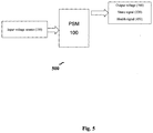
- the power supply module function in a standalone mode is as depicted in Fig. 5 . Standalone mode is utilized when the required power is within the defined capacity of a single power supply.
- two power supply modules are connected in parallel, though the required power maybe within the defined capacity of a single power supply.
- all connected modules share load current equally.
- the healthy power supply module will continue to work normally by providing the required load current.
- the power supply modules are working in the multiple power supply mode though the requirement of power is within the capacity of one power supply to increase reliability of the power supply system.
- multiple power supply modules may be connected together having multiple combinations of input voltage source to improve reliability in a distribution automation system.
- the multiple power supply modules may share a common input voltage source or have independent input voltage sources.
- the multiple power supply modules may have input voltage source derived from input voltage sources that are less in number compared with the number of power supply modules connected together.
- two input voltage sources (610 and 620) are used to provide input voltage to three power supply modules 100 connected together.
- Fig. 7 illustrates again a case with two input voltage sources (710 and 720) for three power supply modules (100) but depicting use of a battery backup supply 710 to supply to a power supply module.
Landscapes
- Engineering & Computer Science (AREA)
- Power Engineering (AREA)
- General Physics & Mathematics (AREA)
- Physics & Mathematics (AREA)
- Radar, Positioning & Navigation (AREA)
- Automation & Control Theory (AREA)
- Electromagnetism (AREA)
- Theoretical Computer Science (AREA)
- Life Sciences & Earth Sciences (AREA)
- Sustainable Development (AREA)
- Sustainable Energy (AREA)
- General Engineering & Computer Science (AREA)
- Dc-Dc Converters (AREA)
- Direct Current Feeding And Distribution (AREA)
Claims (9)
- Alimentation électrique modulaire (100) pour système d'automatisation de distribution, l'alimentation électrique modulaire (100) pouvant être connectée en parallèle et comprenant:un moyen pour connecter une source d'alimentation d'entrée (110) à l'alimentation électrique modulaire et pour connecter la sortie de l'alimentation électrique modulaire à des dispositifs externes;un moyen de régulation (120) comprenant un élément de commutation qui est commandé par un amplificateur d'erreur de tension pour réguler une tension continue de sortie (160);un module de rectification (140) générant la tension continue de sortie (160);un transformateur (130) présentant un côté primaire raccordé au moyen de régulation (120) et aux une ou plusieurs sources d'alimentation d'entrée, et le côté secondaire étant connecté au module de rectification (140);dans laquelle l'élément de commutation est adaptée pour commander le courant du côté primaire du transformateur (130);un moyen de rétroaction de tension (150) destiné à fournir un signal de rétroaction de tension;un module de commande de partage de charge (210) responsable de la commande de partage de charge présentant un signal de partage de charge pour commander le partage de charge pour l'alimentation électrique modulaire;dans laquelle l'alimentation électrique modulaire (100) est par ailleurs munie d'un amplificateur de filtre (310) destiné à conditionner le signal de rétroaction de tension dans la boucle de commande de tension, ledit amplificateur de filtre (310) étant connecté au côté secondaire du transformateur (130) pour réduire l'effet du bruit dans l'alimentation électrique modulaire, dans lequel l'amplificateur de filtre (310) atténue le bruit dû à la commutation et empêche le bruit d'aller à l'amplificateur d'erreur de tension du côté primaire du moyen de régulation (120), et amplifie le bruit dû à la fréquence de ligne de 50/60Hz et à la variation de charge;dans laquelle le signal de sortie de l'amplificateur de filtre (310) est combiné avec un signal de sortie d'une boucle de commande de partage de charge dans le module de commande de partage de charge (210) pour former un signal de sortie du module de commande de partage de charge (210), le module de commande de partage de charge (210) recevant le signal de partage de charge d'un bus de partage de charge (220) et recevant une rétroaction de courant de charge du côté secondaire du transformateur (130), dans laquelle le signal de sortie du module de commande de partage de charge (210) est alimenté vers l'amplificateur d'erreur de tension du moyen de régulation (120),dans laquelle l'alimentation électrique modulaire (100) rend activement le courant de charge égal au signal de partage de charge en commandant le moyen de régulation (120) et dans laquelle les variations affectant une boucle de commande de charge ne sont prises en compte que par le faible gain fourni par l'amplificateur d'erreur de tension du côté primaire du moyen de régulation (120),et dans laquelle l'amplificateur de filtre (310) du côté secondaire et l'amplificateur d'erreur de tension du côté primaire du moyen de régulation (120) ont une réponse en fréquence différente pour obtenir une stabilité sur une ample plage de tensions d'entrée et différentes sources d'alimentation d'entrée pour les alimentations électriques modulaires connectées en parallèle à partage de charge égal.
- Alimentation électrique modulaire selon la revendication 1, dans laquelle le moyen de rétroaction de tension (150) comprend un diviseur de tension présentant des éléments résistifs.
- Alimentation électrique modulaire selon la revendication 1, dans laquelle l'amplificateur de filtre (310) atténue les bruits de hautes fréquences apparaissant dans l'alimentation électrique modulaire.
- Alimentation électrique modulaire selon la revendication 1, dans laquelle l'alimentation électrique modulaire comprend par ailleurs un module de contrôle de santé (440) destiné à déduire l'état de santé de l'alimentation électrique modulaire sur base de la comparaison de la tension continue de sortie (160) et d'un signal dérivé d'un module de rectification équivalent (420) connecté au secondaire du transformateur (130).
- Système d'alimentations électriques modulaires (300) pour système d'automatisation de distribution, comprenant:une pluralité d'alimentations électriques modulaires (100) avec au moins une alimentation électrique modulaire selon la revendication 1, où les moyens pour connecter à une source d'alimentation d'entrée (110) de l'alimentation électrique modulaire (100) et pour connecter la sortie de l'alimentation électrique modulaire (100) à des dispositifs externes sont des moyens pour connecter à une ou plusieurs sources d'alimentation d'entrée (110) et pour connecter les sorties respectives en parallèle;un bus de tension de sortie commun (230) connectant la tension continue de sortie respective de la pluralité d'alimentations électriques modulaires (100);un bus de partage de courant commun (220) connectant le signal de partage de charge pour le module de commande de partage de charge respectif (210) de la pluralité d'alimentations électriques modulaires (100);et dans lequel au moins une alimentation électrique modulaire (100) parmi la pluralité d'alimentations électriques modulaires (100) sont connectées entre elles à la sortie en parallèle.
- Système d'alimentations électriques modulaires selon la revendication 5, dans lequel la pluralité d'alimentations électriques modulaires sont munies de sources de courant d'entrée indépendantes pour chacune des alimentations électriques modulaires.
- Système d'alimentations électriques modulaires selon la revendication 5, dans lequel au moins deux alimentations électriques modulaires parmi la pluralité d'alimentations électriques modulaires sont munies d'une source d'alimentation d'entrée commune.
- Système d'alimentations électriques modulaires selon la revendication 5, dans lequel au moins une alimentation électrique modulaire parmi la pluralité d'alimentations électriques modulaires est munie d'une source d'entrée à batterie de secours.
- Système d'alimentations électriques modulaires selon la revendication 5, dans lequel au moins deux alimentations électriques modulaires parmi la pluralité d'alimentations électriques modulaires sont connectées en parallèle à l'aide de leur moyen de connexion respectif pour connecter leur borne de tension continue de sortie respective au bus de tension de sortie commun (230) et pour connecter leur signal de partage de charge respectif pour leur module de commande de partage de charge respectif (210) au bus de partage de courant commun (220) sans réglage additionnel ou utilisation d'un dispositif additionnel ou signal additionnel du système d'alimentations électriques modulaires pour le partage de charge proportionnel dans lesdites au moins deux alimentations électriques modulaires connectées en parallèle.
Applications Claiming Priority (2)
| Application Number | Priority Date | Filing Date | Title |
|---|---|---|---|
| IN2096CH2011 | 2011-06-21 | ||
| PCT/IB2012/001235 WO2012176051A1 (fr) | 2011-06-21 | 2012-06-21 | Alimentation électrique modulaire pour un système d'automatisation de distribution |
Publications (2)
| Publication Number | Publication Date |
|---|---|
| EP2724457A1 EP2724457A1 (fr) | 2014-04-30 |
| EP2724457B1 true EP2724457B1 (fr) | 2017-01-18 |
Family
ID=46601856
Family Applications (1)
| Application Number | Title | Priority Date | Filing Date |
|---|---|---|---|
| EP12741379.7A Active EP2724457B1 (fr) | 2011-06-21 | 2012-06-21 | Alimentation électrique modulaire pour un système d'automatisation de distribution |
Country Status (4)
| Country | Link |
|---|---|
| US (1) | US9640990B2 (fr) |
| EP (1) | EP2724457B1 (fr) |
| CN (1) | CN103814512B (fr) |
| WO (1) | WO2012176051A1 (fr) |
Families Citing this family (9)
| Publication number | Priority date | Publication date | Assignee | Title |
|---|---|---|---|---|
| KR20170002365A (ko) * | 2014-05-08 | 2017-01-06 | 미쓰비시덴키 가부시키가이샤 | 전원 다중화 시스템 및 피전력 급전 유닛 |
| US10211644B2 (en) * | 2016-02-26 | 2019-02-19 | Abb Schweiz Ag | System and method for regulating voltage in a low voltage power distribution system |
| US10082856B1 (en) * | 2016-09-29 | 2018-09-25 | Juniper Networks, Inc. | Performing a health check on power supply modules that operate in a current sharing mode |
| CN106787850A (zh) * | 2016-12-29 | 2017-05-31 | 施耐德万高(天津)电气设备有限公司 | 自动转换开关电器控制器专用电源 |
| CN107070262A (zh) * | 2016-12-29 | 2017-08-18 | 施耐德万高(天津)电气设备有限公司 | 自动转换开关电器控制器专用电源 |
| KR102942698B1 (ko) * | 2020-04-07 | 2026-03-23 | 엘지이노텍 주식회사 | 부하분담 제어장치 |
| CN114301153B (zh) * | 2020-09-22 | 2024-05-10 | 西安诺瓦星云科技股份有限公司 | 电源备份控制电路卡和led显示控制系统 |
| TWI825794B (zh) * | 2022-06-21 | 2023-12-11 | 群光電能科技股份有限公司 | 電源供應系統及其供電控制方法 |
| CN115333075B (zh) * | 2022-09-05 | 2025-03-18 | 广东美的暖通设备有限公司 | 开关电源的负载分配控制系统、方法、装置和空调设备 |
Citations (2)
| Publication number | Priority date | Publication date | Assignee | Title |
|---|---|---|---|---|
| EP1783568A1 (fr) * | 2004-08-02 | 2007-05-09 | The University of Electro-Communications | Contrôleur numerique robuste et son dispositif de conception |
| US20070133236A1 (en) * | 2005-12-14 | 2007-06-14 | Sanken Electric Co., Ltd. | DC-DC Converter for overvoltage protection |
Family Cites Families (11)
| Publication number | Priority date | Publication date | Assignee | Title |
|---|---|---|---|---|
| US5138543A (en) * | 1991-05-31 | 1992-08-11 | At&T Bell Laboratories | Output voltage estimating circuit for a power converter having galvanic isolation between input and output circuits |
| US6009000A (en) * | 1999-02-05 | 1999-12-28 | The Aerospace Corporation | Shared-bus current sharing parallel connected current-mode DC to DC converters |
| US6433522B1 (en) * | 2001-05-02 | 2002-08-13 | The Aerospace Corporation | Fault tolerant maximum power tracking solar power system |
| JP3624186B2 (ja) * | 2002-03-15 | 2005-03-02 | Tdk株式会社 | スイッチング電源装置用の制御回路及びこれを用いたスイッチング電源装置 |
| TW538586B (en) * | 2002-05-27 | 2003-06-21 | Richtek Technology Corp | Two-step ripple-free multi-phase converter and the converting method thereof |
| US6670794B1 (en) * | 2002-07-12 | 2003-12-30 | Richtek Technology Corp. | Multi-phase DC-to-DC buck converter with multi-phase current balance and adjustable load regulation |
| EP1574696A3 (fr) * | 2004-03-10 | 2006-01-04 | Delphi Technologies, Inc. | Unité d'alimentation pour un circuit de commande d'un injecteur de carburant |
| US7479772B2 (en) * | 2005-02-25 | 2009-01-20 | The Regents Of The University Of Colorado | Active current sharing multiphase DC-DC converter |
| US7541793B2 (en) * | 2005-06-07 | 2009-06-02 | Delta Electronics, Inc. | Parallel power supply with active droop current sharing circuit having current limiting function |
| US8400794B2 (en) * | 2007-10-02 | 2013-03-19 | Ching Hsiung Liu | Power system |
| US8829868B2 (en) * | 2011-07-18 | 2014-09-09 | Crane Electronics, Inc. | Power converter apparatus and method with output current sensing and compensation for current limit/current share operation |
-
2012
- 2012-06-21 WO PCT/IB2012/001235 patent/WO2012176051A1/fr not_active Ceased
- 2012-06-21 CN CN201280030918.XA patent/CN103814512B/zh active Active
- 2012-06-21 EP EP12741379.7A patent/EP2724457B1/fr active Active
-
2013
- 2013-12-20 US US14/136,729 patent/US9640990B2/en active Active
Patent Citations (2)
| Publication number | Priority date | Publication date | Assignee | Title |
|---|---|---|---|---|
| EP1783568A1 (fr) * | 2004-08-02 | 2007-05-09 | The University of Electro-Communications | Contrôleur numerique robuste et son dispositif de conception |
| US20070133236A1 (en) * | 2005-12-14 | 2007-06-14 | Sanken Electric Co., Ltd. | DC-DC Converter for overvoltage protection |
Also Published As
| Publication number | Publication date |
|---|---|
| CN103814512A (zh) | 2014-05-21 |
| EP2724457A1 (fr) | 2014-04-30 |
| WO2012176051A1 (fr) | 2012-12-27 |
| US20140111008A1 (en) | 2014-04-24 |
| US9640990B2 (en) | 2017-05-02 |
| CN103814512B (zh) | 2017-08-29 |
Similar Documents
| Publication | Publication Date | Title |
|---|---|---|
| EP2724457B1 (fr) | Alimentation électrique modulaire pour un système d'automatisation de distribution | |
| US11762405B2 (en) | Power combiner and balancer | |
| US7773395B2 (en) | Uniform converter input voltage distribution power system | |
| US6009000A (en) | Shared-bus current sharing parallel connected current-mode DC to DC converters | |
| EP1844533B1 (fr) | Procédé de statisme compensé permettant de mettre en parallele des alimentations (procede de statisme c) | |
| EP2984745B1 (fr) | Commande de chute de tension au sein d'une alimentation à découpage commandé en tension | |
| EP2724206B1 (fr) | Système d'alimentation électrique | |
| US20220052609A1 (en) | Power distribution architecture with series-connected bus converter | |
| US10531587B2 (en) | Method and apparatus for modular power distribution | |
| JP6086867B2 (ja) | 燃料電池制御装置および方法 | |
| US9793711B2 (en) | Modularly redundant DC-DC power supply arrangement having outputs that can be connected in parallel | |
| EP2830205A2 (fr) | Alimentation à découpage avec partage de courant et de température | |
| US9362748B2 (en) | Power system with combination of active current sharing and droop current sharing and power system assembly using the same | |
| US8351229B2 (en) | Current sharing power system | |
| WO2014028301A1 (fr) | Systèmes et procédés à blocs d'alimentation multiples | |
| CN103999319A (zh) | 并联逆变器系统的自适应负载分担 | |
| EP1107417A2 (fr) | Circuit et procédé pour génerer une rétroaction estimée pour le régulateur d'un module esclave d'alimentation dans un schema parallèle de maítre/esclave | |
| US10998759B2 (en) | Uninterruptible power supply with DC output | |
| KR20130096421A (ko) | 데이터센터의 전원공급시스템 | |
| Siri et al. | Current-sharing/voltage-distribution control for interconnected dc-dc converters | |
| Angkititrakul et al. | Design considerations of 1.2 kW redundant parallel DC/DC power supplies | |
| KR20140068822A (ko) | 데이터센터의 전원공급시스템 |
Legal Events
| Date | Code | Title | Description |
|---|---|---|---|
| PUAI | Public reference made under article 153(3) epc to a published international application that has entered the european phase |
Free format text: ORIGINAL CODE: 0009012 |
|
| 17P | Request for examination filed |
Effective date: 20131220 |
|
| AK | Designated contracting states |
Kind code of ref document: A1 Designated state(s): AL AT BE BG CH CY CZ DE DK EE ES FI FR GB GR HR HU IE IS IT LI LT LU LV MC MK MT NL NO PL PT RO RS SE SI SK SM TR |
|
| DAX | Request for extension of the european patent (deleted) | ||
| 17Q | First examination report despatched |
Effective date: 20150105 |
|
| REG | Reference to a national code |
Ref country code: DE Ref legal event code: R079 Ref document number: 602012027987 Country of ref document: DE Free format text: PREVIOUS MAIN CLASS: H02M0003335000 Ipc: H02M0003280000 |
|
| GRAP | Despatch of communication of intention to grant a patent |
Free format text: ORIGINAL CODE: EPIDOSNIGR1 |
|
| RIC1 | Information provided on ipc code assigned before grant |
Ipc: H02M 3/335 20060101ALI20160708BHEP Ipc: H02J 11/00 20060101ALI20160708BHEP Ipc: H02M 3/28 20060101AFI20160708BHEP Ipc: H02J 1/10 20060101ALI20160708BHEP |
|
| INTG | Intention to grant announced |
Effective date: 20160727 |
|
| GRAS | Grant fee paid |
Free format text: ORIGINAL CODE: EPIDOSNIGR3 |
|
| GRAA | (expected) grant |
Free format text: ORIGINAL CODE: 0009210 |
|
| RAP1 | Party data changed (applicant data changed or rights of an application transferred) |
Owner name: ABB SCHWEIZ AG |
|
| AK | Designated contracting states |
Kind code of ref document: B1 Designated state(s): AL AT BE BG CH CY CZ DE DK EE ES FI FR GB GR HR HU IE IS IT LI LT LU LV MC MK MT NL NO PL PT RO RS SE SI SK SM TR |
|
| REG | Reference to a national code |
Ref country code: GB Ref legal event code: FG4D |
|
| REG | Reference to a national code |
Ref country code: CH Ref legal event code: EP |
|
| REG | Reference to a national code |
Ref country code: AT Ref legal event code: REF Ref document number: 863421 Country of ref document: AT Kind code of ref document: T Effective date: 20170215 |
|
| REG | Reference to a national code |
Ref country code: IE Ref legal event code: FG4D |
|
| REG | Reference to a national code |
Ref country code: DE Ref legal event code: R096 Ref document number: 602012027987 Country of ref document: DE |
|
| REG | Reference to a national code |
Ref country code: NL Ref legal event code: MP Effective date: 20170118 |
|
| REG | Reference to a national code |
Ref country code: LT Ref legal event code: MG4D |
|
| REG | Reference to a national code |
Ref country code: AT Ref legal event code: MK05 Ref document number: 863421 Country of ref document: AT Kind code of ref document: T Effective date: 20170118 |
|
| REG | Reference to a national code |
Ref country code: FR Ref legal event code: PLFP Year of fee payment: 6 |
|
| PG25 | Lapsed in a contracting state [announced via postgrant information from national office to epo] |
Ref country code: NL Free format text: LAPSE BECAUSE OF FAILURE TO SUBMIT A TRANSLATION OF THE DESCRIPTION OR TO PAY THE FEE WITHIN THE PRESCRIBED TIME-LIMIT Effective date: 20170118 |
|
| PG25 | Lapsed in a contracting state [announced via postgrant information from national office to epo] |
Ref country code: GR Free format text: LAPSE BECAUSE OF FAILURE TO SUBMIT A TRANSLATION OF THE DESCRIPTION OR TO PAY THE FEE WITHIN THE PRESCRIBED TIME-LIMIT Effective date: 20170419 Ref country code: IS Free format text: LAPSE BECAUSE OF FAILURE TO SUBMIT A TRANSLATION OF THE DESCRIPTION OR TO PAY THE FEE WITHIN THE PRESCRIBED TIME-LIMIT Effective date: 20170518 Ref country code: NO Free format text: LAPSE BECAUSE OF FAILURE TO SUBMIT A TRANSLATION OF THE DESCRIPTION OR TO PAY THE FEE WITHIN THE PRESCRIBED TIME-LIMIT Effective date: 20170418 Ref country code: LT Free format text: LAPSE BECAUSE OF FAILURE TO SUBMIT A TRANSLATION OF THE DESCRIPTION OR TO PAY THE FEE WITHIN THE PRESCRIBED TIME-LIMIT Effective date: 20170118 Ref country code: HR Free format text: LAPSE BECAUSE OF FAILURE TO SUBMIT A TRANSLATION OF THE DESCRIPTION OR TO PAY THE FEE WITHIN THE PRESCRIBED TIME-LIMIT Effective date: 20170118 Ref country code: FI Free format text: LAPSE BECAUSE OF FAILURE TO SUBMIT A TRANSLATION OF THE DESCRIPTION OR TO PAY THE FEE WITHIN THE PRESCRIBED TIME-LIMIT Effective date: 20170118 |
|
| PG25 | Lapsed in a contracting state [announced via postgrant information from national office to epo] |
Ref country code: LV Free format text: LAPSE BECAUSE OF FAILURE TO SUBMIT A TRANSLATION OF THE DESCRIPTION OR TO PAY THE FEE WITHIN THE PRESCRIBED TIME-LIMIT Effective date: 20170118 Ref country code: SE Free format text: LAPSE BECAUSE OF FAILURE TO SUBMIT A TRANSLATION OF THE DESCRIPTION OR TO PAY THE FEE WITHIN THE PRESCRIBED TIME-LIMIT Effective date: 20170118 Ref country code: PT Free format text: LAPSE BECAUSE OF FAILURE TO SUBMIT A TRANSLATION OF THE DESCRIPTION OR TO PAY THE FEE WITHIN THE PRESCRIBED TIME-LIMIT Effective date: 20170518 Ref country code: RS Free format text: LAPSE BECAUSE OF FAILURE TO SUBMIT A TRANSLATION OF THE DESCRIPTION OR TO PAY THE FEE WITHIN THE PRESCRIBED TIME-LIMIT Effective date: 20170118 Ref country code: AT Free format text: LAPSE BECAUSE OF FAILURE TO SUBMIT A TRANSLATION OF THE DESCRIPTION OR TO PAY THE FEE WITHIN THE PRESCRIBED TIME-LIMIT Effective date: 20170118 Ref country code: ES Free format text: LAPSE BECAUSE OF FAILURE TO SUBMIT A TRANSLATION OF THE DESCRIPTION OR TO PAY THE FEE WITHIN THE PRESCRIBED TIME-LIMIT Effective date: 20170118 Ref country code: BG Free format text: LAPSE BECAUSE OF FAILURE TO SUBMIT A TRANSLATION OF THE DESCRIPTION OR TO PAY THE FEE WITHIN THE PRESCRIBED TIME-LIMIT Effective date: 20170418 Ref country code: PL Free format text: LAPSE BECAUSE OF FAILURE TO SUBMIT A TRANSLATION OF THE DESCRIPTION OR TO PAY THE FEE WITHIN THE PRESCRIBED TIME-LIMIT Effective date: 20170118 |
|
| REG | Reference to a national code |
Ref country code: DE Ref legal event code: R097 Ref document number: 602012027987 Country of ref document: DE |
|
| PG25 | Lapsed in a contracting state [announced via postgrant information from national office to epo] |
Ref country code: RO Free format text: LAPSE BECAUSE OF FAILURE TO SUBMIT A TRANSLATION OF THE DESCRIPTION OR TO PAY THE FEE WITHIN THE PRESCRIBED TIME-LIMIT Effective date: 20170118 Ref country code: SK Free format text: LAPSE BECAUSE OF FAILURE TO SUBMIT A TRANSLATION OF THE DESCRIPTION OR TO PAY THE FEE WITHIN THE PRESCRIBED TIME-LIMIT Effective date: 20170118 Ref country code: EE Free format text: LAPSE BECAUSE OF FAILURE TO SUBMIT A TRANSLATION OF THE DESCRIPTION OR TO PAY THE FEE WITHIN THE PRESCRIBED TIME-LIMIT Effective date: 20170118 Ref country code: IT Free format text: LAPSE BECAUSE OF FAILURE TO SUBMIT A TRANSLATION OF THE DESCRIPTION OR TO PAY THE FEE WITHIN THE PRESCRIBED TIME-LIMIT Effective date: 20170118 Ref country code: CZ Free format text: LAPSE BECAUSE OF FAILURE TO SUBMIT A TRANSLATION OF THE DESCRIPTION OR TO PAY THE FEE WITHIN THE PRESCRIBED TIME-LIMIT Effective date: 20170118 |
|
| PLBE | No opposition filed within time limit |
Free format text: ORIGINAL CODE: 0009261 |
|
| STAA | Information on the status of an ep patent application or granted ep patent |
Free format text: STATUS: NO OPPOSITION FILED WITHIN TIME LIMIT |
|
| PG25 | Lapsed in a contracting state [announced via postgrant information from national office to epo] |
Ref country code: DK Free format text: LAPSE BECAUSE OF FAILURE TO SUBMIT A TRANSLATION OF THE DESCRIPTION OR TO PAY THE FEE WITHIN THE PRESCRIBED TIME-LIMIT Effective date: 20170118 Ref country code: SM Free format text: LAPSE BECAUSE OF FAILURE TO SUBMIT A TRANSLATION OF THE DESCRIPTION OR TO PAY THE FEE WITHIN THE PRESCRIBED TIME-LIMIT Effective date: 20170118 |
|
| 26N | No opposition filed |
Effective date: 20171019 |
|
| PG25 | Lapsed in a contracting state [announced via postgrant information from national office to epo] |
Ref country code: MC Free format text: LAPSE BECAUSE OF FAILURE TO SUBMIT A TRANSLATION OF THE DESCRIPTION OR TO PAY THE FEE WITHIN THE PRESCRIBED TIME-LIMIT Effective date: 20170118 |
|
| REG | Reference to a national code |
Ref country code: CH Ref legal event code: PL |
|
| PG25 | Lapsed in a contracting state [announced via postgrant information from national office to epo] |
Ref country code: SI Free format text: LAPSE BECAUSE OF FAILURE TO SUBMIT A TRANSLATION OF THE DESCRIPTION OR TO PAY THE FEE WITHIN THE PRESCRIBED TIME-LIMIT Effective date: 20170118 |
|
| PGFP | Annual fee paid to national office [announced via postgrant information from national office to epo] |
Ref country code: GB Payment date: 20171127 Year of fee payment: 6 |
|
| REG | Reference to a national code |
Ref country code: IE Ref legal event code: MM4A |
|
| PG25 | Lapsed in a contracting state [announced via postgrant information from national office to epo] |
Ref country code: LU Free format text: LAPSE BECAUSE OF NON-PAYMENT OF DUE FEES Effective date: 20170621 Ref country code: IE Free format text: LAPSE BECAUSE OF NON-PAYMENT OF DUE FEES Effective date: 20170621 Ref country code: LI Free format text: LAPSE BECAUSE OF NON-PAYMENT OF DUE FEES Effective date: 20170630 Ref country code: CH Free format text: LAPSE BECAUSE OF NON-PAYMENT OF DUE FEES Effective date: 20170630 |
|
| REG | Reference to a national code |
Ref country code: BE Ref legal event code: MM Effective date: 20170630 |
|
| REG | Reference to a national code |
Ref country code: FR Ref legal event code: PLFP Year of fee payment: 7 |
|
| PG25 | Lapsed in a contracting state [announced via postgrant information from national office to epo] |
Ref country code: BE Free format text: LAPSE BECAUSE OF NON-PAYMENT OF DUE FEES Effective date: 20170630 |
|
| PG25 | Lapsed in a contracting state [announced via postgrant information from national office to epo] |
Ref country code: MT Free format text: LAPSE BECAUSE OF NON-PAYMENT OF DUE FEES Effective date: 20170621 |
|
| GBPC | Gb: european patent ceased through non-payment of renewal fee |
Effective date: 20180621 |
|
| PG25 | Lapsed in a contracting state [announced via postgrant information from national office to epo] |
Ref country code: GB Free format text: LAPSE BECAUSE OF NON-PAYMENT OF DUE FEES Effective date: 20180621 |
|
| PG25 | Lapsed in a contracting state [announced via postgrant information from national office to epo] |
Ref country code: HU Free format text: LAPSE BECAUSE OF FAILURE TO SUBMIT A TRANSLATION OF THE DESCRIPTION OR TO PAY THE FEE WITHIN THE PRESCRIBED TIME-LIMIT; INVALID AB INITIO Effective date: 20120621 |
|
| PG25 | Lapsed in a contracting state [announced via postgrant information from national office to epo] |
Ref country code: CY Free format text: LAPSE BECAUSE OF NON-PAYMENT OF DUE FEES Effective date: 20170118 |
|
| PG25 | Lapsed in a contracting state [announced via postgrant information from national office to epo] |
Ref country code: MK Free format text: LAPSE BECAUSE OF FAILURE TO SUBMIT A TRANSLATION OF THE DESCRIPTION OR TO PAY THE FEE WITHIN THE PRESCRIBED TIME-LIMIT Effective date: 20170118 |
|
| PG25 | Lapsed in a contracting state [announced via postgrant information from national office to epo] |
Ref country code: TR Free format text: LAPSE BECAUSE OF FAILURE TO SUBMIT A TRANSLATION OF THE DESCRIPTION OR TO PAY THE FEE WITHIN THE PRESCRIBED TIME-LIMIT Effective date: 20170118 |
|
| PG25 | Lapsed in a contracting state [announced via postgrant information from national office to epo] |
Ref country code: AL Free format text: LAPSE BECAUSE OF FAILURE TO SUBMIT A TRANSLATION OF THE DESCRIPTION OR TO PAY THE FEE WITHIN THE PRESCRIBED TIME-LIMIT Effective date: 20170118 |
|
| PGFP | Annual fee paid to national office [announced via postgrant information from national office to epo] |
Ref country code: DE Payment date: 20250618 Year of fee payment: 14 |
|
| PGFP | Annual fee paid to national office [announced via postgrant information from national office to epo] |
Ref country code: FR Payment date: 20250624 Year of fee payment: 14 |