EP2724697A2 - Auxiliaire d'entraînement séparé pour chaises roulantes - Google Patents
Auxiliaire d'entraînement séparé pour chaises roulantes Download PDFInfo
- Publication number
- EP2724697A2 EP2724697A2 EP13188217.7A EP13188217A EP2724697A2 EP 2724697 A2 EP2724697 A2 EP 2724697A2 EP 13188217 A EP13188217 A EP 13188217A EP 2724697 A2 EP2724697 A2 EP 2724697A2
- Authority
- EP
- European Patent Office
- Prior art keywords
- axle
- aid
- drive aid
- drive
- wheelchair
- Prior art date
- Legal status (The legal status is an assumption and is not a legal conclusion. Google has not performed a legal analysis and makes no representation as to the accuracy of the status listed.)
- Withdrawn
Links
- 230000008878 coupling Effects 0.000 claims abstract description 49
- 238000010168 coupling process Methods 0.000 claims abstract description 49
- 238000005859 coupling reaction Methods 0.000 claims abstract description 49
- 230000000295 complement effect Effects 0.000 claims description 4
- 230000000903 blocking effect Effects 0.000 claims description 3
- MOVRNJGDXREIBM-UHFFFAOYSA-N aid-1 Chemical compound O=C1NC(=O)C(C)=CN1C1OC(COP(O)(=O)OC2C(OC(C2)N2C3=C(C(NC(N)=N3)=O)N=C2)COP(O)(=O)OC2C(OC(C2)N2C3=C(C(NC(N)=N3)=O)N=C2)COP(O)(=O)OC2C(OC(C2)N2C3=C(C(NC(N)=N3)=O)N=C2)COP(O)(=O)OC2C(OC(C2)N2C(NC(=O)C(C)=C2)=O)COP(O)(=O)OC2C(OC(C2)N2C3=C(C(NC(N)=N3)=O)N=C2)COP(O)(=O)OC2C(OC(C2)N2C3=C(C(NC(N)=N3)=O)N=C2)COP(O)(=O)OC2C(OC(C2)N2C3=C(C(NC(N)=N3)=O)N=C2)COP(O)(=O)OC2C(OC(C2)N2C(NC(=O)C(C)=C2)=O)COP(O)(=O)OC2C(OC(C2)N2C3=C(C(NC(N)=N3)=O)N=C2)COP(O)(=O)OC2C(OC(C2)N2C3=C(C(NC(N)=N3)=O)N=C2)COP(O)(=O)OC2C(OC(C2)N2C3=C(C(NC(N)=N3)=O)N=C2)COP(O)(=O)OC2C(OC(C2)N2C(NC(=O)C(C)=C2)=O)COP(O)(=O)OC2C(OC(C2)N2C3=C(C(NC(N)=N3)=O)N=C2)COP(O)(=O)OC2C(OC(C2)N2C3=C(C(NC(N)=N3)=O)N=C2)COP(O)(=O)OC2C(OC(C2)N2C3=C(C(NC(N)=N3)=O)N=C2)CO)C(O)C1 MOVRNJGDXREIBM-UHFFFAOYSA-N 0.000 description 24
- 210000002683 foot Anatomy 0.000 description 6
- 238000004519 manufacturing process Methods 0.000 description 4
- 230000001133 acceleration Effects 0.000 description 3
- 230000005484 gravity Effects 0.000 description 3
- 230000005540 biological transmission Effects 0.000 description 2
- 239000000969 carrier Substances 0.000 description 2
- 210000004744 fore-foot Anatomy 0.000 description 2
- 239000012237 artificial material Substances 0.000 description 1
- 239000011248 coating agent Substances 0.000 description 1
- 238000000576 coating method Methods 0.000 description 1
- 238000002485 combustion reaction Methods 0.000 description 1
- 239000002131 composite material Substances 0.000 description 1
- 238000006073 displacement reaction Methods 0.000 description 1
- 230000000694 effects Effects 0.000 description 1
- 239000000446 fuel Substances 0.000 description 1
- 239000000463 material Substances 0.000 description 1
- 230000007246 mechanism Effects 0.000 description 1
- 239000002184 metal Substances 0.000 description 1
- 230000009467 reduction Effects 0.000 description 1
- 230000001960 triggered effect Effects 0.000 description 1
- 238000003466 welding Methods 0.000 description 1
- 239000002023 wood Substances 0.000 description 1
Images

Classifications
-
- A—HUMAN NECESSITIES
- A61—MEDICAL OR VETERINARY SCIENCE; HYGIENE
- A61G—TRANSPORT, PERSONAL CONVEYANCES, OR ACCOMMODATION SPECIALLY ADAPTED FOR PATIENTS OR DISABLED PERSONS; OPERATING TABLES OR CHAIRS; CHAIRS FOR DENTISTRY; FUNERAL DEVICES
- A61G5/00—Chairs or personal conveyances specially adapted for patients or disabled persons, e.g. wheelchairs
- A61G5/003—Wheelchairs attached to a cycle steerable by an attendant
-
- A—HUMAN NECESSITIES
- A61—MEDICAL OR VETERINARY SCIENCE; HYGIENE
- A61G—TRANSPORT, PERSONAL CONVEYANCES, OR ACCOMMODATION SPECIALLY ADAPTED FOR PATIENTS OR DISABLED PERSONS; OPERATING TABLES OR CHAIRS; CHAIRS FOR DENTISTRY; FUNERAL DEVICES
- A61G5/00—Chairs or personal conveyances specially adapted for patients or disabled persons, e.g. wheelchairs
- A61G5/04—Chairs or personal conveyances specially adapted for patients or disabled persons, e.g. wheelchairs motor-driven
- A61G5/047—Chairs or personal conveyances specially adapted for patients or disabled persons, e.g. wheelchairs motor-driven by a modular detachable drive system
-
- A—HUMAN NECESSITIES
- A61—MEDICAL OR VETERINARY SCIENCE; HYGIENE
- A61G—TRANSPORT, PERSONAL CONVEYANCES, OR ACCOMMODATION SPECIALLY ADAPTED FOR PATIENTS OR DISABLED PERSONS; OPERATING TABLES OR CHAIRS; CHAIRS FOR DENTISTRY; FUNERAL DEVICES
- A61G5/00—Chairs or personal conveyances specially adapted for patients or disabled persons, e.g. wheelchairs
- A61G5/10—Parts, details or accessories
-
- A—HUMAN NECESSITIES
- A61—MEDICAL OR VETERINARY SCIENCE; HYGIENE
- A61G—TRANSPORT, PERSONAL CONVEYANCES, OR ACCOMMODATION SPECIALLY ADAPTED FOR PATIENTS OR DISABLED PERSONS; OPERATING TABLES OR CHAIRS; CHAIRS FOR DENTISTRY; FUNERAL DEVICES
- A61G5/00—Chairs or personal conveyances specially adapted for patients or disabled persons, e.g. wheelchairs
- A61G5/10—Parts, details or accessories
- A61G5/1051—Arrangements for steering
-
- B—PERFORMING OPERATIONS; TRANSPORTING
- B62—LAND VEHICLES FOR TRAVELLING OTHERWISE THAN ON RAILS
- B62B—HAND-PROPELLED VEHICLES, e.g. HAND CARTS OR PERAMBULATORS; SLEDGES
- B62B5/00—Accessories or details specially adapted for hand carts
- B62B5/0026—Propulsion aids
- B62B5/0079—Towing by connecting to another vehicle
-
- B—PERFORMING OPERATIONS; TRANSPORTING
- B62—LAND VEHICLES FOR TRAVELLING OTHERWISE THAN ON RAILS
- B62B—HAND-PROPELLED VEHICLES, e.g. HAND CARTS OR PERAMBULATORS; SLEDGES
- B62B5/00—Accessories or details specially adapted for hand carts
- B62B5/002—Adaptations for moving the carts by wheel chair users or other disabled persons
-
- B—PERFORMING OPERATIONS; TRANSPORTING
- B62—LAND VEHICLES FOR TRAVELLING OTHERWISE THAN ON RAILS
- B62B—HAND-PROPELLED VEHICLES, e.g. HAND CARTS OR PERAMBULATORS; SLEDGES
- B62B5/00—Accessories or details specially adapted for hand carts
- B62B5/0026—Propulsion aids
- B62B5/0033—Electric motors
Definitions
- the invention relates to a separate drive aid for rollable person or load carrier, in particular for wheelchairs, with a drive motor, at least one drive wheel, at least one seat for a driver, and a coupling device by which the drive aid to the passenger or load carrier is repeatedly releasably fastened wherein the coupling means comprises a hinge disposed between the coupling means and the drive wheel.
- the present invention is suitable for driving a variety of load carriers such as workshop trolley, file trolley or handcart.
- load carriers such as workshop trolley, file trolley or handcart.
- the present invention is described on a wheelchair, without excluding the use of other trolleys.
- the pushing device off DE 20 2006 014 217 U1 uses a unicycle, which is attached by means of a push rod to a cross strut on the wheelchair frame.
- the cross strut is fastened by means of clamp closures on the vertical tubes of the wheelchair frame.
- To improve the trailing characteristics of the saddle is offset from the drive wheel.
- the combination of this publication should be quite difficult.
- the device for the purpose of pushing off EP 1 364 634 A2 has a board-shaped main body.
- two transverse boards are attached to the lower end tubes of the wheelchair frame on the latter. Between these, the front end of the main body is then clamped and connected by a bolt with this.
- This bolt also represents a swivel joint and forms the steering axis of the vehicle. Also this vehicle requires considerable forces when steering and is limited maneuverability.
- the drive aid according to the invention can essentially consist of a body which contains the drive unit and a linkage which establishes the connection to the wheelchair.
- the drive wheel or the drive wheels On the body of the drive aid, the drive wheel or the drive wheels, at least one seat for a driver and lateral footrests can be located.
- the drive aid can have only one single wheel, which simultaneously represents the drive wheel of the drive aid and thus of the combined vehicle.
- the drive aid may also have two wheels, in particular two wheels positioned next to each other, which together form a double wheel.
- the seating for the driver may be positioned over the drive wheel so that the weight of the driver is directed into the ground via the drive wheel. This is advantageous because excessive loading of the wheelchair with the weight of the driver is avoided.
- a seat for example, a bicycle saddle can be used.
- the seat can be height adjustable to suit the size of the rider.
- the seat can be carried by a support whose axis in the direction of gravity extends the axis of the drive wheel cuts. In this case, deviations of the axes can be tolerated up to 2 cm.
- the seat can be folded to store the drive help space-saving can. It can then be transported, for example, in the trunk of a car.
- the drive assist can have lateral footrests for the driver.
- These footrests can also be designed as pedal, with which driving force and braking force are controlled.
- the foot lever can be configured as a rocker whose longer end points in the direction of travel and serves as a support for the forefoot of the driver, and whose shorter end opposite to the direction of travel and serves as a support for the heel of the driver.
- the size of the footrests can correspond to common shoe sizes, with the length preferably between 15 and 35 cm. can amount.
- the rockers may be arranged so that the driver's feet can rest on the driver without effort. From this rest position, the rockers can be easily operated as a pedal. The support of the feet and the operation of the foot pedal without effort are important features for the use of drive assistance by the elderly.
- axle coupling device can be attached.
- these axle extensions can be connected to each other, for example by a pipe or a rod, so that a single axis is formed. The connection then constitutes an axle coupling.
- This axle coupling can essentially be a part of the coupling device.
- the drive aid may have a joint between the coupling device and the drive wheel, which is aligned with a wheel axle of the wheelchair.
- This joint can have two joint axes, wherein the joint can be movable in two degrees of freedom.
- the two joint axes can preferably intersect.
- the coupling device may have a transverse to the direction of travel axle strut and a pointing between the hinge and the drive wheel in the direction of travel push rod.
- the push rod of the drive aid may be attached, so that a T-shaped linkage is formed.
- the axle strut can extend continuously between the axle extensions of the wheelchair.
- the axle strut can be penetrated by the push rod.
- a hinge axis can be arranged.
- the axle strut can be rotatably connected to the axle extensions.
- the thrust of the drive aid acts in this case on the linkage on the axes of the wheelchair wheels.
- the push rod and the axle strut may be the hinge, so that the vehicle is steerable and can also compensate for differences in the inclination of the ground.
- the axis of rotation and the pivot axis of the joint can be as close as possible to the axis of the two wheelchair wheels.
- the axis of rotation of the joint intersects the axis of the wheelchair wheels, whereby a slight steering of the combined vehicle and wheelchair drive is possible. Design and production-related deviations up to 4 cm can be tolerated.
- the pivot axis of the joint may coincide with the axis of the wheelchair wheels. In this case, design and production-related deviations can be tolerated up to 2 cm.
- This type of attachment of the drive aid on the axis of the wheelchair wheels leads to an advantageous power transmission between drive and wheelchair. There are no tilting induced as in other drive aids in the prior art. Since the driving force is not transmitted through the frame, there are no losses due to movement or deformation of the frame. The type of attachment makes it possible to retrofit the drive assistance even with existing wheelchairs.
- a folding mechanism for the seat can be designed so that the movement of the seat is transmitted via an actuator, consisting of power transmission elements, such as linkage or Bowden cables, to a coupling device of the drive aid.
- an actuator consisting of power transmission elements, such as linkage or Bowden cables
- a lock on the wheelchair can be triggered, which couples the drive aid to the wheelchair when the seat is opened, and releases again when the seat is folded.
- the coupling device may comprise adapters which are attached to the axle extensions of the individually suspended wheels.
- the adapters may be tubular extensions that are fixedly connected to the axle extensions.
- the axle strut of the coupling device can be designed to be complementary to the axle extensions.
- the axle strut of the coupling device can be half-tubular in the axial direction at its ends, so that it can be placed on the axle extensions with these ends.
- the axle strut may have fastening elements which are designed to be complementary to the axle extensions.
- the fastening elements may have locking elements, wherein the locking elements from a mounting position in which they are released from the axle extensions, may be movable into a coupling position in which they are locked to the axle extensions.
- the blocking elements may be connected to an actuating device and be movable by the actuating device between the assembly position and the coupling position.
- fasteners such as e.g. Bolts or pins are located in the axle strut, which are movable and can be inserted with one end into the tubular axle extensions.
- the fastening members can then each be with one end in the Achsstrebe and the other end in the retainer, so that the drive aid is locked to the wheelchair.
- the fastening elements may be formed as rotatable sleeves, which are inserted in the open state in the semi-tubular ends of the axle strut, so that they can be placed on the axle extensions. Upon rotation of the sleeves, these can then surround the axle extensions and thereby secure the drive aid on the wheelchair.
- the fastening members may be connected to the actuating device. Unfolding the seat can then lock the fasteners to the axle extensions, so that the drive aid is attached to the wheelchair.
- the drive aid is in this case in a working position.
- the seat can be movable from an operating position to a transport position, wherein the cubature of the drive aid in this transport position is smaller than in the operating position.
- the actuating device may be coupled to the operating side with the seat, wherein in the transport position the locking elements are transferred via the actuating device in the mounting position, so that the drive aid is released from the passenger or load carrier and are transferred in the operating position via the actuating device in the coupling position, in the drive aid is attached to the passenger or load carrier.
- Folding the seat can separate the fastening members from the retaining members, whereby the drive assistance is released from the wheelchair and is in a transport position.
- the drive aid may have a stand that supports the drive aid when it is not attached to the wheelchair. This stand can be foldable to attach it to the body of the drive aid when it is not needed.
- the wheelchair handles can be used to steer the combined vehicle out of the wheelchair and the drive aid. It is then no additional steering device necessary. At the Push rod of the drive aid, the distance between the drive aid and wheelchair can be changed. Thereby, the distance of the handles to the driver on the height and arm length of the driver can be adjusted so that it can easily reach the handles and hold securely.
- An advantageous embodiment of the drive aid can use an electric motor as a drive and a battery as an energy source.
- a fuel cell may be used or, instead of an electric motor, an internal combustion engine.
- electric motor and accumulator charging of the battery can be done directly on the device via a socket on the housing, or the accumulator can be removed to load it to a charger.
- the drive unit may have a drive motor with a reduction gear, in particular with a worm gear.
- the speed of the drive aid and the combined vehicle out of the wheelchair and drive aid may be throttled due to the approval, in particular to a walking speed of 6 km / h.
- the drive aid may have a safety device by which a starting acceleration is limited.
- the limitation of the starting acceleration can be achieved in particular by a torque limitation. As a result, an acceleration is possible, which allows a safe driving style for old or sick people.
- Fig. 1 shows a separate drive aid 1, connected to a wheelchair 3 in an operating position 13.
- the drive aid 1 is attached with its coupling device 5 at the wheelchair end of the push rod 7 on the wheelchair 3.
- the seat 9 and the associated support 11 are opened.
- the seat 9 is located above the drive wheel 21, wherein the longitudinal axis 15 extends in the direction of gravity 17, the wheel axle 19 of the drive wheel 21 intersects.
- design-related and production-related deviations of the longitudinal axis 15 of the support 11 and the wheel axle 19 of the drive wheel 21 can be tolerated up to 2 cm.
- the support 11 is captively connected by fastening members 23 with the body 25 of the drive aid 1.
- footrests 27 are located between the seat 9 for the driver and the coupling device 5 laterally on the body 25 of the drive aid 1.
- the footrests 27 are by fastening members 28 to the body 25 of the drive aid. 1 inextricably linked. They serve to support the feet of the driver while driving. Width and length of the footrests 27 are adapted to the size of the shoe of an average tall person, so that in each case the entire foot of the driver can be placed. This allows a comfortable and safe posture and a relaxed driving style, which is particularly advantageous for the elderly.
- the footrests 27 have the shape of a rocker with a longer end 33 and a shorter end 31.
- the longer end 33 points in the direction of travel 29 and serves to support the forefoot of the driver, the shorter end 31 has opposite to the direction 29 and serves to support the Heel of the driver.
- the rocker-shaped footrest 27 is pivotable about an axis pointing transversely to the direction of travel in two directions.
- the pivot axis preferably coincides with the axis of the fastening element 28.
- the footrests 27 are designed as pedal, with which driving force and braking force can be controlled.
- a depression of the front end 33 of the footrest 27 may, for. B. control the strength of the driving force.
- a pressure on the rear end 31 of the footrest 27 can actuate the brakes of the vehicle 43.
- the pivoting range of the footrests 27 is limited to a range that allows the execution of the control functions.
- the top of the footrests 27 is designed substantially flat. It may be provided with a structure or coating which has anti-slip properties to prevent foot slipping while riding. This improves safety for the driver.
- the footrests 27 may be made of a metal. However, with sufficient strength, other materials such as e.g. Artificial or composite materials or wood are used.
- the diameter 35 of the drive wheel 21 is preferably less than half the diameter 37 of the wheelchair wheels 39 of the wheelchair 3.
- the drive wheel 21 is captively connected to the body 25 of the drive aid 1 and is located to a part within the body 25. This is a touch prevents the driver with the drive wheel 21.
- Inside the body 25 of the drive aid 1 are also the drive unit consisting of an electric motor and an energy source, such. B. an accumulator.
- the handles 41 of the wheelchair 3 serve as handles for the driver and at the same time as handlebar grips for the combined vehicle 43 from wheelchair 3 and drive aid 1.
- the driver assumes a secure posture on the drive aid 1 and can steer the vehicle 43 comfortably and smoothly.
- Fig. 2 shows the embodiment Fig. 1 in the operating position 13 in plan view. For clarity, only the elements necessary for the description of the wheelchair 3 are shown.
- the wheels 39 are suspended individually.
- the two wheels 39 form the pair of wheels 40.
- the axes 45 of the wheels 39 pierce the tubes 47 of the wheelchair frame 49 and are continued for a distance to the inside.
- the coupling device 5 of the drive aid 1 is fastened captive. Wheelchair and drive aid 1 then together form the vehicle 43.
- the coupling device 5 is essentially formed from a transverse to the direction 29 axis strut 53.
- the axle strut 53 is substantially tubular. It is captively connected via an axle coupling 57 with the axle extensions 51. If the axle strut 53 can not be fastened directly to the axle extensions 51, the coupling device 5 can have adapters 52, which are first attached to the axle extensions 51 in order to allow attachment of the axle strut 53.
- the coupling device 5 thus forms a common rigid axis of the two wheelchair wheels 39. This increases the stability of the vehicle 43 and improves the driving characteristics. The thrust of the drive aid 1 is transmitted to the wheelchair wheels 39 via this axis.
- the axle strut 53 is pivotally connected to the wheelchair wheel axles 45, so that the axis of the axle strut 53 forms a pivot axis 59 of the combined vehicle 43.
- the axle strut 53 is preferably pivotally connected to the axle extensions 51. Then fall the pivot axis 59 of the vehicle 43 and the common axis 61 of the wheelchair wheels 39 together. This position of the pivot axis 59 makes it possible to significantly improve the driving characteristics of the vehicle 43, in particular when negotiating small obstacles or when driving on slopes.
- the axle strut 53 is not pivotably connected to the axle extensions 51 but fixed immovably to the wheelchair 3, the connection of the push rod 7 to the axle strut 53 can be made pivotable. In this case, design-related deviations of the position of the pivot axis 59 to the axis 61 of the wheels 39 up to 2 cm are tolerable.
- the push rod 7 is connected at its end pointing in the direction of travel 29 with the coupling device 5.
- the axle strut 53 has a receptacle 54. At this receptacle 54 it is penetrated by the push rod 7.
- the push rod 7 is connected captively to the axle strut 53 by a fastener 63. Push rod 7 and axle strut 53 together form a substantially T-shaped linkage 55.
- connection of the push rod 7 to the axle strut 53 is designed to be rotatable about a vertical axis.
- the receptacle 54 is designed as an opening whose size and cross section of the push rod is adapted and is sufficiently large to allow movement about the vertical axis.
- This axis forms the steering axle 65 of the combined vehicle 43.
- the steering axle 65 preferably coincides with the axis of the fastener 63.
- the steering shaft 65 intersects the axis 61 of the wheelchair wheels 39. This allows a particularly easy steering of the combined vehicle 43. Design and manufacturing-related deviations from the steering axis 65 and the axis 61 of the pair of wheels of up to 4 cm are tolerable.
- connection of push rod 7 to the Achsstrebe 53 thus forms a rotatable joint in two axes 66, wherein the joint 66 is in the cutting area of the T-shaped rod 55.
- the support 11 of the seat 9 is fork-shaped and connected to the two fork legs 14 on the sides of the body 25 of the drive aid 1 by fastening members 23.
- Fig. 3 shows the drive aid 1 in the transport position 67 uncoupled from the wheelchair 3.
- the seat 9 and the associated support 11 are folded in this position.
- the linkage 55 is designed so that the seat 9 can be folded to save space.
- the drive aid 1 has a smaller cubature in the transport position 67 than in the operating position 13. It is therefore space-saving and easy to stow, for example in the trunk of a car.
- the folding of seat 9 and the support 11 has released the coupling device 5 from the wheelchair 3 via an actuating device 64.
- the drive aid 1 is therefore disconnected from the wheelchair 3.
- the drive aid 1 rests on a stand 69, which can be applied in the operating position 13 to the body 25 of the drive aid 1 or inserted into the body 25.
- the fork-shaped support 11 has a transverse strut 12 which connects the two fork legs 14 with each other.
- the crossbar 12 gives the support 11 additional stability.
- the cross strut 12 is designed as a carrying handle 16 or can carry a carrying handle, so that the drive aid 1 can be raised and transported in the transport position 67 on this carrying handle 16.
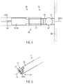
- Fig. 4 shows a plan view of an embodiment of fasteners 73 of an axle clutch 57 of the drive aid 1 in an operating position 13.
- the axle extensions 51 of the wheelchair wheels 39 have been extended by tubular adapter 52.
- the adapters 52 can be attached to the wheelchair 3, inter alia, by welding or screwing. On this adapter 52, the axle strut 53 of the coupling device 5 is placed.
- axle strut 53 The ends 71 of the axle strut 53 are semi-tubular shaped to fit onto the tubular adapters 52.
- sliding elements 74 In the interior of the axle strut 53 are sliding elements 74 as locking elements 78 which are inserted in a coupling position 70 in the adapter 52 and thereby lock the drive aid 1 on the wheelchair 3.
- a mounting position 68 These locking elements are pushed back into the axle strut 53, so that they no longer engage in the adapter 52, whereby the coupling device 5 is released from the wheelchair 3.
- the locking elements 78 are connected via an actuating device with the support 11 of the seat 9.
- Fig. 5 shows as an exemplary embodiment, the schematic representation of a fastener 73 with a locking element 78, which is formed by a rotary member 77.
- the fastening element 73 is shown in the coupling position 70.
- the rotary member 77 is rotatable about the longitudinal axis 79 of the axle strut 53 and has a sleeve 81. In the assembly position 68, the rotary member 77 is rotated so that the sleeve 81 is opened and fits into the semi-tubular end 71 of the axle strut 53. The coupling device 5 can then be placed on the adapter 52.
- the rotary member 77 can be transferred by rotation in the coupling position 70.
- the sleeve 81 engages around the adapter 52, so that the coupling device 5 is locked to the wheelchair 3.
- the drive aid 1 is then connected to the wheelchair 3.
- the rotary members 77 can be connected to an actuator 64. If the seat 9 is transferred into the transport position 67, the rotary element 77 is moved into the assembly position 68 and the drive aid 1 is released from the wheelchair 3. If the seat 9, however, transferred to the operating position 13, the rotary member 77 is moved to the coupling position 70 and the drive aid 1 locked to the wheelchair 3.
Landscapes
- Health & Medical Sciences (AREA)
- Life Sciences & Earth Sciences (AREA)
- Animal Behavior & Ethology (AREA)
- General Health & Medical Sciences (AREA)
- Public Health (AREA)
- Veterinary Medicine (AREA)
- Engineering & Computer Science (AREA)
- Chemical & Material Sciences (AREA)
- Combustion & Propulsion (AREA)
- Transportation (AREA)
- Mechanical Engineering (AREA)
- Nursing (AREA)
- Motorcycle And Bicycle Frame (AREA)
- Carriages For Children, Sleds, And Other Hand-Operated Vehicles (AREA)
Applications Claiming Priority (1)
| Application Number | Priority Date | Filing Date | Title |
|---|---|---|---|
| DE102012219689.7A DE102012219689A1 (de) | 2012-10-26 | 2012-10-26 | Separate Antriebshilfe für Rollstühle |
Publications (2)
| Publication Number | Publication Date |
|---|---|
| EP2724697A2 true EP2724697A2 (fr) | 2014-04-30 |
| EP2724697A3 EP2724697A3 (fr) | 2014-05-21 |
Family
ID=49354494
Family Applications (1)
| Application Number | Title | Priority Date | Filing Date |
|---|---|---|---|
| EP13188217.7A Withdrawn EP2724697A3 (fr) | 2012-10-26 | 2013-10-11 | Auxiliaire d'entraînement séparé pour chaises roulantes |
Country Status (2)
| Country | Link |
|---|---|
| EP (1) | EP2724697A3 (fr) |
| DE (1) | DE102012219689A1 (fr) |
Citations (2)
| Publication number | Priority date | Publication date | Assignee | Title |
|---|---|---|---|---|
| EP1364634A2 (fr) | 2001-08-31 | 2003-11-26 | Bernd Rothenburg | Dispositif d'accouplement d'un aggrégat d'entraínement par poussée à un fauteuil roulant ou en cas d'un entraínement corporel ou motorisé du fauteuil roulant ceci est déplacé par derrière par traction |
| DE202006014217U1 (de) | 2006-09-16 | 2006-11-23 | Kappner, Kurt, Dipl.-Ing. (FH) | Schubeinrichtung für Rollstühle |
Family Cites Families (9)
| Publication number | Priority date | Publication date | Assignee | Title |
|---|---|---|---|---|
| US2482585A (en) * | 1946-01-15 | 1949-09-20 | Gerhard G Hauptman | Combination bicycle and baby carriage |
| US3524512A (en) * | 1968-02-21 | 1970-08-18 | Elton L Voeks | Self-propelled driving and steering truck for shopping carts |
| US3575250A (en) * | 1968-12-23 | 1971-04-20 | Battery Power Unit Co Inc | Self-propelled electric vehicle and battery mount |
| DE8710562U1 (de) * | 1986-07-31 | 1987-10-29 | Schramm, Siegfried, 3208 Giesen | Fahrzeug zum Transport von Personen und/oder Lasten |
| US4771840A (en) * | 1987-04-15 | 1988-09-20 | Orthokinetics, Inc. | Articulated power-driven shopping cart |
| DE3714106A1 (de) * | 1987-04-28 | 1988-11-10 | Helmut Prof Dr Reichmann | Kupplungsanschluss fuer kombinationsfahrzeuge aus rollstuhl und fahrrad |
| US4770431A (en) * | 1987-08-05 | 1988-09-13 | Helmut Kulik | Snap on wheel chair bicycle converter |
| IL121778A (en) * | 1997-09-16 | 2001-01-11 | Hillel Hillel | Lift transit vehicle |
| JP2001346836A (ja) * | 2000-06-07 | 2001-12-18 | Genzo Nishigori | 介護者操作電動移動車 |
-
2012
- 2012-10-26 DE DE102012219689.7A patent/DE102012219689A1/de not_active Withdrawn
-
2013
- 2013-10-11 EP EP13188217.7A patent/EP2724697A3/fr not_active Withdrawn
Patent Citations (2)
| Publication number | Priority date | Publication date | Assignee | Title |
|---|---|---|---|---|
| EP1364634A2 (fr) | 2001-08-31 | 2003-11-26 | Bernd Rothenburg | Dispositif d'accouplement d'un aggrégat d'entraínement par poussée à un fauteuil roulant ou en cas d'un entraínement corporel ou motorisé du fauteuil roulant ceci est déplacé par derrière par traction |
| DE202006014217U1 (de) | 2006-09-16 | 2006-11-23 | Kappner, Kurt, Dipl.-Ing. (FH) | Schubeinrichtung für Rollstühle |
Also Published As
| Publication number | Publication date |
|---|---|
| DE102012219689A1 (de) | 2014-04-30 |
| EP2724697A3 (fr) | 2014-05-21 |
Similar Documents
| Publication | Publication Date | Title |
|---|---|---|
| EP3145800B1 (fr) | Trottinette à voie unique | |
| WO2019101635A1 (fr) | Déambulateur à roulettes, à entraînement électrique | |
| DE102011111419B4 (de) | Fahrzeug mit einem Fahrbrett zum Abstellen wenigstens der Füße des Fahrers des Fahrzeugs | |
| EP3488839A1 (fr) | Déambulateur à entraînement électrique | |
| DE102016101870A1 (de) | Lastenrad | |
| EP3898395A1 (fr) | Véhicule électrique à fonction de transport et procédé pour modifier l'état de celui-ci | |
| EP3652052B1 (fr) | Trottinette et méthode d'utilisation d'un trottinette | |
| EP2724698B1 (fr) | Auxiliaire d'entraînement séparé pour chaises roulantes | |
| EP2895129B1 (fr) | Fauteuil roulant | |
| DE3303218A1 (de) | Dreirad zur befoerderung von personen und guetern | |
| DE102012014027B3 (de) | Vorrichtung zum Umrüsten eines Rollators in ein motorbetriebenes Fortbewegungsmittel | |
| EP0085091A1 (fr) | Appareil de traction pour fauteuil roulant | |
| DE2724553C2 (de) | Elektrisch angetriebener, als Selbstfahrer ausgebildeter Krankenfahrstuhl | |
| DE102017205080B4 (de) | Kraftfahrzeug mit mobilem Fahrzeugsitz und mobiler Fahrzeugsitz | |
| EP3569214A1 (fr) | Véhicule | |
| EP2724697A2 (fr) | Auxiliaire d'entraînement séparé pour chaises roulantes | |
| DE102015105321A1 (de) | Zusammenfaltbares Zweirad und Verfahren zum Zusammenfalten eines Zweirads | |
| DE102019121133B4 (de) | Bewegungsvorrichtung für Personen | |
| DE102012015651A1 (de) | Nutzfahrzeug | |
| DE102009024522A1 (de) | Baukastensystem für teilzerlegbare Fahrzeuge | |
| DE102015116236A1 (de) | Rollstuhl mit Antrieb | |
| DE202025106797U1 (de) | Elektromotorischer Hilfs- oder Nachrüstantrieb | |
| DE202010015482U1 (de) | Gymnastik-Laufrad mit Elektroantrieb | |
| DE202009001418U1 (de) | Gymnastik-Laufrad | |
| DE202006014217U1 (de) | Schubeinrichtung für Rollstühle |
Legal Events
| Date | Code | Title | Description |
|---|---|---|---|
| PUAL | Search report despatched |
Free format text: ORIGINAL CODE: 0009013 |
|
| PUAI | Public reference made under article 153(3) epc to a published international application that has entered the european phase |
Free format text: ORIGINAL CODE: 0009012 |
|
| 17P | Request for examination filed |
Effective date: 20131011 |
|
| AK | Designated contracting states |
Kind code of ref document: A2 Designated state(s): AL AT BE BG CH CY CZ DE DK EE ES FI FR GB GR HR HU IE IS IT LI LT LU LV MC MK MT NL NO PL PT RO RS SE SI SK SM TR |
|
| AX | Request for extension of the european patent |
Extension state: BA ME |
|
| AK | Designated contracting states |
Kind code of ref document: A3 Designated state(s): AL AT BE BG CH CY CZ DE DK EE ES FI FR GB GR HR HU IE IS IT LI LT LU LV MC MK MT NL NO PL PT RO RS SE SI SK SM TR |
|
| AX | Request for extension of the european patent |
Extension state: BA ME |
|
| RIC1 | Information provided on ipc code assigned before grant |
Ipc: A61G 5/00 20060101ALI20140417BHEP Ipc: A61G 5/10 20060101ALI20140417BHEP Ipc: A61G 5/04 20130101AFI20140417BHEP |
|
| STAA | Information on the status of an ep patent application or granted ep patent |
Free format text: STATUS: THE APPLICATION IS DEEMED TO BE WITHDRAWN |
|
| 18D | Application deemed to be withdrawn |
Effective date: 20141122 |