EP2724765A2 - Système de capture de CO2 - Google Patents
Système de capture de CO2 Download PDFInfo
- Publication number
- EP2724765A2 EP2724765A2 EP13184528.1A EP13184528A EP2724765A2 EP 2724765 A2 EP2724765 A2 EP 2724765A2 EP 13184528 A EP13184528 A EP 13184528A EP 2724765 A2 EP2724765 A2 EP 2724765A2
- Authority
- EP
- European Patent Office
- Prior art keywords
- sorbent
- water
- capture system
- absorption tower
- steam
- Prior art date
- Legal status (The legal status is an assumption and is not a legal conclusion. Google has not performed a legal analysis and makes no representation as to the accuracy of the status listed.)
- Granted
Links
- XLYOFNOQVPJJNP-UHFFFAOYSA-N water Substances O XLYOFNOQVPJJNP-UHFFFAOYSA-N 0.000 claims abstract description 137
- 239000002594 sorbent Substances 0.000 claims abstract description 136
- 238000010521 absorption reaction Methods 0.000 claims abstract description 30
- 230000001172 regenerating effect Effects 0.000 claims abstract description 6
- 229910021645 metal ion Inorganic materials 0.000 claims description 32
- 239000003595 mist Substances 0.000 claims description 25
- 230000002940 repellent Effects 0.000 claims description 23
- 239000005871 repellent Substances 0.000 claims description 23
- 238000011084 recovery Methods 0.000 claims description 21
- 239000003463 adsorbent Substances 0.000 claims description 15
- 239000000463 material Substances 0.000 claims description 15
- 238000000034 method Methods 0.000 claims description 14
- 239000011248 coating agent Substances 0.000 claims description 11
- 238000000576 coating method Methods 0.000 claims description 11
- 239000002245 particle Substances 0.000 claims description 11
- 239000007788 liquid Substances 0.000 claims description 9
- OKTJSMMVPCPJKN-UHFFFAOYSA-N Carbon Chemical compound [C] OKTJSMMVPCPJKN-UHFFFAOYSA-N 0.000 claims description 6
- 229910052799 carbon Inorganic materials 0.000 claims description 6
- 229910021536 Zeolite Inorganic materials 0.000 claims description 5
- HNPSIPDUKPIQMN-UHFFFAOYSA-N dioxosilane;oxo(oxoalumanyloxy)alumane Chemical compound O=[Si]=O.O=[Al]O[Al]=O HNPSIPDUKPIQMN-UHFFFAOYSA-N 0.000 claims description 5
- 239000010457 zeolite Substances 0.000 claims description 5
- 238000011144 upstream manufacturing Methods 0.000 claims description 4
- 238000001914 filtration Methods 0.000 claims description 2
- 230000008021 deposition Effects 0.000 abstract description 2
- CURLTUGMZLYLDI-UHFFFAOYSA-N Carbon dioxide Chemical compound O=C=O CURLTUGMZLYLDI-UHFFFAOYSA-N 0.000 description 189
- 229910002092 carbon dioxide Inorganic materials 0.000 description 188
- 239000001569 carbon dioxide Substances 0.000 description 188
- 239000007789 gas Substances 0.000 description 11
- 238000002485 combustion reaction Methods 0.000 description 6
- 238000009833 condensation Methods 0.000 description 4
- 230000005494 condensation Effects 0.000 description 4
- 239000011164 primary particle Substances 0.000 description 4
- 239000007787 solid Substances 0.000 description 4
- 230000003247 decreasing effect Effects 0.000 description 3
- 238000004090 dissolution Methods 0.000 description 3
- 230000000694 effects Effects 0.000 description 3
- 230000005484 gravity Effects 0.000 description 3
- 239000002244 precipitate Substances 0.000 description 3
- 238000001179 sorption measurement Methods 0.000 description 3
- QGZKDVFQNNGYKY-UHFFFAOYSA-N Ammonia Chemical compound N QGZKDVFQNNGYKY-UHFFFAOYSA-N 0.000 description 2
- VYPSYNLAJGMNEJ-UHFFFAOYSA-N Silicium dioxide Chemical compound O=[Si]=O VYPSYNLAJGMNEJ-UHFFFAOYSA-N 0.000 description 2
- GWEVSGVZZGPLCZ-UHFFFAOYSA-N Titan oxide Chemical compound O=[Ti]=O GWEVSGVZZGPLCZ-UHFFFAOYSA-N 0.000 description 2
- MCMNRKCIXSYSNV-UHFFFAOYSA-N Zirconium dioxide Chemical compound O=[Zr]=O MCMNRKCIXSYSNV-UHFFFAOYSA-N 0.000 description 2
- 238000006243 chemical reaction Methods 0.000 description 2
- 238000006482 condensation reaction Methods 0.000 description 2
- 238000010828 elution Methods 0.000 description 2
- 230000002209 hydrophobic effect Effects 0.000 description 2
- 230000007774 longterm Effects 0.000 description 2
- 230000000149 penetrating effect Effects 0.000 description 2
- 229920000642 polymer Polymers 0.000 description 2
- 239000013153 zeolitic imidazolate framework Substances 0.000 description 2
- BVKZGUZCCUSVTD-UHFFFAOYSA-L Carbonate Chemical compound [O-]C([O-])=O BVKZGUZCCUSVTD-UHFFFAOYSA-L 0.000 description 1
- XSQUKJJJFZCRTK-UHFFFAOYSA-N Urea Chemical compound NC(N)=O XSQUKJJJFZCRTK-UHFFFAOYSA-N 0.000 description 1
- 239000002250 absorbent Substances 0.000 description 1
- 230000002745 absorbent Effects 0.000 description 1
- 229910052783 alkali metal Inorganic materials 0.000 description 1
- 150000001340 alkali metals Chemical class 0.000 description 1
- 229910052784 alkaline earth metal Inorganic materials 0.000 description 1
- 150000001342 alkaline earth metals Chemical class 0.000 description 1
- PNEYBMLMFCGWSK-UHFFFAOYSA-N aluminium oxide Inorganic materials [O-2].[O-2].[O-2].[Al+3].[Al+3] PNEYBMLMFCGWSK-UHFFFAOYSA-N 0.000 description 1
- 150000001413 amino acids Chemical class 0.000 description 1
- 229910021529 ammonia Inorganic materials 0.000 description 1
- -1 and thus Substances 0.000 description 1
- 239000004202 carbamide Substances 0.000 description 1
- CETPSERCERDGAM-UHFFFAOYSA-N ceric oxide Chemical compound O=[Ce]=O CETPSERCERDGAM-UHFFFAOYSA-N 0.000 description 1
- 229910000422 cerium(IV) oxide Inorganic materials 0.000 description 1
- 230000000052 comparative effect Effects 0.000 description 1
- 239000011521 glass Substances 0.000 description 1
- 239000004519 grease Substances 0.000 description 1
- 239000005431 greenhouse gas Substances 0.000 description 1
- 238000010438 heat treatment Methods 0.000 description 1
- 239000012535 impurity Substances 0.000 description 1
- 150000002500 ions Chemical class 0.000 description 1
- 238000005259 measurement Methods 0.000 description 1
- 238000000465 moulding Methods 0.000 description 1
- 239000013384 organic framework Substances 0.000 description 1
- 238000001139 pH measurement Methods 0.000 description 1
- 230000035699 permeability Effects 0.000 description 1
- 239000011148 porous material Substances 0.000 description 1
- 239000011347 resin Substances 0.000 description 1
- 229920005989 resin Polymers 0.000 description 1
- 238000000926 separation method Methods 0.000 description 1
- 239000000377 silicon dioxide Substances 0.000 description 1
- 238000010792 warming Methods 0.000 description 1
- 238000009736 wetting Methods 0.000 description 1
Images


Classifications
-
- B—PERFORMING OPERATIONS; TRANSPORTING
- B01—PHYSICAL OR CHEMICAL PROCESSES OR APPARATUS IN GENERAL
- B01D—SEPARATION
- B01D53/00—Separation of gases or vapours; Recovering vapours of volatile solvents from gases; Chemical or biological purification of waste gases, e.g. engine exhaust gases, smoke, fumes, flue gases, aerosols
- B01D53/02—Separation of gases or vapours; Recovering vapours of volatile solvents from gases; Chemical or biological purification of waste gases, e.g. engine exhaust gases, smoke, fumes, flue gases, aerosols by adsorption, e.g. preparative gas chromatography
- B01D53/04—Separation of gases or vapours; Recovering vapours of volatile solvents from gases; Chemical or biological purification of waste gases, e.g. engine exhaust gases, smoke, fumes, flue gases, aerosols by adsorption, e.g. preparative gas chromatography with stationary adsorbents
-
- B—PERFORMING OPERATIONS; TRANSPORTING
- B01—PHYSICAL OR CHEMICAL PROCESSES OR APPARATUS IN GENERAL
- B01D—SEPARATION
- B01D2253/00—Adsorbents used in seperation treatment of gases and vapours
- B01D2253/25—Coated, impregnated or composite adsorbents
-
- B—PERFORMING OPERATIONS; TRANSPORTING
- B01—PHYSICAL OR CHEMICAL PROCESSES OR APPARATUS IN GENERAL
- B01D—SEPARATION
- B01D2257/00—Components to be removed
- B01D2257/50—Carbon oxides
- B01D2257/504—Carbon dioxide
-
- B—PERFORMING OPERATIONS; TRANSPORTING
- B01—PHYSICAL OR CHEMICAL PROCESSES OR APPARATUS IN GENERAL
- B01D—SEPARATION
- B01D2259/00—Type of treatment
- B01D2259/40—Further details for adsorption processes and devices
- B01D2259/40083—Regeneration of adsorbents in processes other than pressure or temperature swing adsorption
- B01D2259/40088—Regeneration of adsorbents in processes other than pressure or temperature swing adsorption by heating
- B01D2259/4009—Regeneration of adsorbents in processes other than pressure or temperature swing adsorption by heating using hot gas
-
- B—PERFORMING OPERATIONS; TRANSPORTING
- B01—PHYSICAL OR CHEMICAL PROCESSES OR APPARATUS IN GENERAL
- B01D—SEPARATION
- B01D53/00—Separation of gases or vapours; Recovering vapours of volatile solvents from gases; Chemical or biological purification of waste gases, e.g. engine exhaust gases, smoke, fumes, flue gases, aerosols
- B01D53/02—Separation of gases or vapours; Recovering vapours of volatile solvents from gases; Chemical or biological purification of waste gases, e.g. engine exhaust gases, smoke, fumes, flue gases, aerosols by adsorption, e.g. preparative gas chromatography
- B01D53/04—Separation of gases or vapours; Recovering vapours of volatile solvents from gases; Chemical or biological purification of waste gases, e.g. engine exhaust gases, smoke, fumes, flue gases, aerosols by adsorption, e.g. preparative gas chromatography with stationary adsorbents
- B01D53/0407—Constructional details of adsorbing systems
- B01D53/0438—Cooling or heating systems
-
- Y—GENERAL TAGGING OF NEW TECHNOLOGICAL DEVELOPMENTS; GENERAL TAGGING OF CROSS-SECTIONAL TECHNOLOGIES SPANNING OVER SEVERAL SECTIONS OF THE IPC; TECHNICAL SUBJECTS COVERED BY FORMER USPC CROSS-REFERENCE ART COLLECTIONS [XRACs] AND DIGESTS
- Y02—TECHNOLOGIES OR APPLICATIONS FOR MITIGATION OR ADAPTATION AGAINST CLIMATE CHANGE
- Y02C—CAPTURE, STORAGE, SEQUESTRATION OR DISPOSAL OF GREENHOUSE GASES [GHG]
- Y02C20/00—Capture or disposal of greenhouse gases
- Y02C20/40—Capture or disposal of greenhouse gases of CO2
Definitions
- the present invention relates to a CO 2 capture system using a CO 2 sorbent.
- the specific component in order to adsorb and separate a certain specific component in a sample gas, first, the specific component is adsorbed on an adsorbent in an adsorption tower having the adsorbent placed therein, thereafter, the specific component is desorbed by heating and aerating the adsorption tower having a given amount of the specific component adsorbed thereon, thereby regenerating the adsorbent.
- CO 2 capture systems using a CO 2 sorbent are not a method in which heated steam is allowed to flow therein when regenerating the CO 2 sorbent, but a method with a mechanism utilizing a difference in pressure of adsorption amount.
- a CO 2 capture system using a difference in CO 2 capturing amount caused by a change in pressure of a CO 2 sorbent is described in, for example, JP-A-2009-220101 (PTL 2).
- An object of the present invention is to provide a CO 2 capture system having a unit configured to reduce the possibility of contaminating a circulating water system with a CO 2 sorbent.
- the present application includes a plurality of units configured to solve the above problem, and one example is a CO 2 capture system, which includes a CO 2 sorbent, a CO 2 absorption tower having the CO 2 sorbent encapsulated therein, and a channel for recovering water condensed in the CO 2 absorption tower to a circulating water system, and which uses steam gas for regenerating the CO 2 sorbent, wherein a unit configured to reduce the outflow of the CO 2 sorbent to the circulating water system is provided.
- a CO 2 capture system which includes a CO 2 sorbent, a CO 2 absorption tower having the CO 2 sorbent encapsulated therein, and a channel for recovering water condensed in the CO 2 absorption tower to a circulating water system, and which uses steam gas for regenerating the CO 2 sorbent, wherein a unit configured to reduce the outflow of the CO 2 sorbent to the circulating water system is provided.
- the possibility of dissolving the CO 2 sorbent in the condensed water and contaminating the circulating water system with the CO 2 sorbent can be significantly reduced.
- Fig. 1 shows an example of a CO 2 capture system of the present invention, and is a view showing a structure in a step of desorbing and recovering CO 2 .
- CO 2 is desorbed by allowing high-temperature steam to flow in the CO 2 absorption tower through a steam channel 102 and bringing the high-temperature steam into contact with the CO 2 sorbent to heat the CO 2 sorbent.
- the present invention is directed to a CO 2 capture system characterized by having a unit configured to reduce the outflow of the CO 2 sorbent to the circulating water system.
- a mist removing unit 103 As the unit configured to reduce the elution of the CO 2 sorbent to the circulating water system, a mist removing unit 103, a water repellent finish for the CO 2 sorbent, and a CO 2 sorbent recovery filter 107 are provided. An effect is exhibited even by any one of these units, and it is also possible to provide one or more units in combination.
- the steam After removing mist in the steam by the mist removing unit 103, the steam is allowed to flow in the absorption tower 100.
- Water condensed in a CO 2 sorbent packed bed in the absorption tower 100 is accumulated in a condensed water pool 105 and recovered through a condensed water recovery channel 106 after completing the step of desorbing CO 2 .
- a condensation reaction occurs, and therefore, by applying a water repellent finish to the CO 2 sorbent, the possibility of dissolving the CO 2 sorbent in condensed water can be reduced.
- the condensed water After filtering the condensed water having passed through the condensed water recovery channel 106 with the CO 2 sorbent recovery filter 107, the condensed water is returned to a circulating water channel 109.
- the component can be removed by the CO 2 sorbent recovery filter 107, and therefore, the purity of the circulating water can be maintained, and by molding the recovered component of the CO 2 sorbent, it can be used again as the CO 2 sorbent.
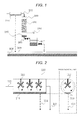
- a propeller 112 is provided in the steam channel as a swirling flow generating unit, and by a centrifugal force generated by the rotation of the propeller, water having a large particle diameter is adhered to the wall surface, and thereafter, condensed water 113 falling by the force of gravity is accumulated.
- water derived from the removed mist can be recovered through a recovery channel 114. Further, it is also possible to reduce the humidity so that steam is less likely to be condensed by providing a moisture absorbent in the steam channel in place of the swirling flow generating unit.
- CO 2 sorbent to which a water repellent finish is applied for example, a material having a high-specific surface area including silica, alumina, titania, zirconia, ceria, zeolite, a polymeric material, active carbon, MOF (Molecular Organic Framework), ZIF (Zeolitic Imidazolate Framework), or the like may be used, or a material including an oxide or a carbonate of an alkali metal or an alkaline earth metal, or the like may be used.
- MOF Molecular Organic Framework
- ZIF Zeolitic Imidazolate Framework
- the shape of the CO 2 sorbent may be a particle, a honeycomb, an air-permeable plate, or the like, and may be any shape as long as the CO 2 sorbent has air permeability and can allow steam to flow therethrough even if it has a shape other than the above-described shapes.
- Fig. 3 shows a schematic view of the CO 2 sorbent in the case where a spherical CO 2 sorbent 116 has been treated with a water repellent coating 119.
- the drawing cannot give sufficient expression, it is assumed that while the particle diameter of a primary particle 117 of the CO 2 sorbent is several nanometers to several tens of micrometers, the particle diameter of the CO 2 sorbent 116 is about 0.5 to 100 mm, and therefore, the primary particles of the CO 2 sorbent are packed therein more densely than as shown in the illustration of the drawing.
- a water repellent coating only to the outer surface, it is possible to prevent the CO 2 sorbent from dissolving due to wetting by the condensed water.
- an arbitrary method such as a grease-based coating (such as a wax), a resin-based coating (such as a polymer or a fluororesin), or a glass-based coating may be used, however, it is preferred to use a method with which a coating agent is hardly peeled off.
- JP-A-5-123525 an example of using hydrophobic zeolite as a CO 2 sorbent is described, however, in the structure disclosed in JP-A-5-123525 , dry air is introduced when desorbing CO 2 , and therefore, steam gas as disclosed in this application cannot be allowed to flow. If a water repellent finish is applied as disclosed in the present invention, in the structure in which steam is allowed to flow in the CO 2 absorption tower in the step of desorbing CO 2 , any material can be used whether it is hydrophobic or hydrophilic.
- a metal ion constituting the CO 2 sorbent is dissolved in the condensed water filtered through the CO 2 sorbent recovery filter 107, for example, as shown in Fig. 4 , by providing an adsorbent material 128 which adsorbs a CO 2 sorbent constituting metal ion, the CO 2 sorbent constituting metal ion may be captured and recovered. If the dissolved ion is a metal ion, for example, by adding a nonmetallic alkaline liquid of urea, ammonia, a basic amino acid, or the like to form a precipitate composed of the metal ion and the alkaline component, and recovery may be performed from the precipitate.
- a metal ion concentration measuring unit 131 which measures a metal ion concentration in the condensed water filtered through the CO 2 sorbent recovery filter 107 shown in Fig. 4 , is provided, and the following procedure may be performed. Only in the case where the metal ion concentration exceeds a defined reference value, a valve 133 is opened to allow the condensed water to flow through a channel provided with the adsorbent material 128 which adsorbs a CO 2 sorbent constituting metal ion, and in the case where the metal ion concentration in the condensed water does not exceed the reference value, a valve 132 is opened and the condensed water is returned to the circulating water system as it is.
- the candidate for the adsorbent material 128 which adsorbs a CO 2 sorbent constituting metal ion is, for example, zeolite, active carbon, or the like.
- the metal ion concentration measuring unit As a simplified method of the metal ion concentration measuring unit, there is a method for inferring the metal ion concentration from the measurement of pH of the condensed water. By using this method, the metal ion concentration can be inferred from the variation in pH, and therefore, the metal ion concentration measurement can be relatively easily performed, which leads to cost reduction.
- the condensed water containing the dissolved CO 2 sorbent is returned to the circulating water system.
- this circulating water is given combustion heat and converted into steam at a place where the circulating water goes, and therefore, the CO 2 sorbent in the form of a solid may be deposited at the place. This may cause a decrease in efficiency of conversion of combustion heat to steam enthalpy, and therefore, it is preferred to prevent this from occurring.
- the CO 2 capture system is provided in other than the combustion boiler, if circulating water is reused, the CO 2 sorbent may be deposited somewhere in the channel to affect an instrument. Further, it may result in a loss of the CO 2 sorbent itself by the outflow thereof after long-term use, and therefore, there is a possibility of decreasing the CO 2 recovery efficiency more than initially estimated after long-term use.
- a CO 2 capture system shown in Fig. 1 will be described. It is a CO 2 capture system configured such that after a step of capturing CO 2 in CO 2 -containing gas by a CO 2 sorbent 101 in a CO 2 absorption tower 100, CO 2 is desorbed by allowing steam with a temperature higher than that of the CO 2 sorbent 101 to flow in the CO 2 absorption tower 100 through a steam channel 102 and bringing the introduced high-temperature steam into contact with the CO 2 sorbent 101 to heat the CO 2 sorbent by the condensation heat. The desorbed CO 2 and steam are recovered through a CO 2 recovery channel 104, and then cooled and separated.
- a mist removing unit 103 is provided upstream of the CO 2 absorption tower, thereby removing a mist component of water having a relatively large particle diameter among the steam, and thereafter, the steam is allowed to flow in the absorption tower 100. Water accumulated in the mist removing unit 103 is returned to a circulating water channel 109 as it is.
- the CO 2 sorbent 101 can be prevented from dissolving in hot water condensed on the CO 2 sorbent 101.
- the condensation of steam is caused mainly on the outer surface of the CO 2 sorbent, and thus, water in the form of a liquid is prevented from penetrating into the inner portion of the CO 2 sorbent, and moreover, condensed water flowing and falling from the upper portion of the CO 2 sorbent bed is prevented from penetrating into the inner portion of the CO 2 sorbent, and thus, the dissolution of the CO 2 sorbent in the condensed water is reduced.
- Water condensed in the CO 2 sorbent packed bed is accumulated in the condensed water pool 105, and recovered through the condensed water recovery channel 106 after completing the step of desorbing CO 2 .
- the condensed water recovered from the condensed water pool 105 contains the slightest amount of the CO 2 sorbent 101, and therefore, the condensed water is filtered through a CO 2 sorbent recovery filter 107 provided downstream of the CO 2 absorption tower. By doing this, the water purity of the circulating water can be maintained, and also the CO 2 sorbent flowing out can be recovered and reused.
- the filtered condensed water is returned to the circulating water channel 109 through which the circulating water 108 flows and reused.
- mist removing unit 103 the water repellent finish for the CO 2 sorbent, and the CO 2 sorbent recovery filter 107, which are the units configured to reduce the elution of the CO 2 sorbent to the circulating water system provided in the first embodiment, and it is also possible to perform the embodiment by combining one or more of these units.
- Fig. 2 illustrates an embodiment in the case where as the mist removing unit provided in the CO 2 capture system described in the first embodiment, a device which separates mist having a large particle diameter from steam gas by a centrifugal force using a swirling flow generating unit is used.
- a mist removing unit 110 shown in Fig. 2 a propeller 112 is provided perpendicular to the steam flowing direction, and the propeller 112 is rotated about the steam flowing direction as an axis.
- the particle diameter of the adhered water in the form of a mist grows over time, and the water falls along the wall surface due to its own weight and is accumulated as the condensed water 113.
- This water contains almost no impurities, and therefore can be returned to the circulating water system through a channel 114 after completing the step of desorbing CO 2 by steam flowing.
- Fig. 3 is an imaginary view of a spherical CO 2 sorbent as an example of the water repellent finish applied to the CO 2 sorbent in the CO 2 capture system according to the first embodiment.
- a CO 2 capturing portion of the CO 2 sorbent is a gap between the primary particles of the CO 2 sorbent and a fine pore present in the primary particle. It is not preferred that a water repellent coating component penetrates thereinto. Therefore, a method in which a water repellent coating is applied under a high CO 2 partial pressure so that the CO 2 sorbent is brought into a state where CO 2 is captured in the CO 2 capturing portion of the CO 2 sorbent, is preferred.
- the water repellent coating component hardly penetrates into the inner portion of the CO 2 sorbent or the CO 2 capturing portion, and therefore, it is possible to apply the water repellent finish only to the outer surface of the CO 2 sorbent, and thus, the possibility of dissolving the outer surface of the CO 2 sorbent in condensed water can be largely reduced.
- a fourth embodiment shown in Fig. 4 conforms to the CO 2 capture system according to the first embodiment.
- it is a CO 2 capture system configured such that after capturing CO 2 in CO 2 -containing gas by a CO 2 sorbent 121 with a water repellent finish in a CO 2 absorption tower 100, CO 2 is desorbed by allowing steam with a temperature higher than that of the CO 2 sorbent 121 to flow in the CO 2 absorption tower 100 through a steam channel 102 and bringing the introduced high-temperature steam into contact with the CO 2 sorbent 121 with a water repellent finish to heat the CO 2 sorbent by the condensation heat.
- a mist removing unit 103 a mist component of water having a relatively large particle diameter among the steam is removed, and thereafter, the steam is allowed to flow in the absorption tower 100.
- the desorbed CO 2 and steam are recovered through a CO 2 recovery channel 104, and then cooled and separated.
- water condensed on the CO 2 sorbent 121 with a water repellent finish is accumulated in a condensed water pool 105 in a lower portion of the absorption tower 100 due to the flow of steam and the force of gravity.
- a valve in a condensed water recovery channel 106 is opened, and the condensed water is recovered.
- the condensed water contains the slightest amount of the CO 2 sorbent, and therefore, the condensed water is filtered through a CO 2 sorbent recovery filter 107.
- a metal ion concentration measuring unit 131 which measures a metal ion concentration in the filtered condensed water, the metal ion concentration in the filtered condensed water is measured.
- a valve 132 for feeding the condensed water to the circulating water system is opened to return the condensed water to the circulating water system, but if the metal ion concentration is higher than the reference value, a valve 133 is opened to allow the condensed water to flow through a metal ion adsorbent material 128 which adsorbs a metal ion constituting the CO 2 sorbent, whereby the metal ion concentration in the condensed water is decreased and the condensed water is returned to a condensed water channel 109.
- metal ion adsorbent material 1208 for example, an adsorbent material of zeolite, active carbon, a polymer, or the like can be used.
- active carbon an adsorbent material containing carbon at 50 wt% or more is preferred.
- the dissolution of even a small amount of the CO 2 sorbent can be controlled, and therefore, the purity of the circulating water can be maintained high.
- an effect is exhibited by any one of these units configured to prevent the outflow of the CO 2 sorbent to the circulating water system including the metal ion adsorbent material in the same manner as in the first embodiment, and it is also possible to perform the embodiment by combining one or more of these units.
- a fifth embodiment shown in Fig. 6 conforms to the CO 2 capture system according to the first embodiment.
- the metal ion concentration measuring unit 131 which measures a metal ion concentration in filtered condensed water, the metal ion concentration in condensed water filtered through a CO 2 sorbent recovery filter 107 is measured.
- a valve 132 for feeding the condensed water to the circulating water system is opened to return the condensed water to the circulating water system, but if the metal ion concentration is higher than the reference value, a valve 156 is opened and also an alkaline liquid is allowed to flow through an alkaline liquid inflow channel 151 provided in this embodiment, the metal ion in the condensed water is precipitated. By removing this precipitate through a filter 157, also the CO 2 sorbent can be recovered. The filtered condensed water is returned to a condensed water channel 109. According also to this CO 2 capture system, the dissolution of even a small amount of the CO 2 sorbent can be controlled, and therefore, the purity of the circulating water can be maintained high.
Landscapes
- Chemical & Material Sciences (AREA)
- Engineering & Computer Science (AREA)
- Analytical Chemistry (AREA)
- General Chemical & Material Sciences (AREA)
- Oil, Petroleum & Natural Gas (AREA)
- Chemical Kinetics & Catalysis (AREA)
- Treating Waste Gases (AREA)
- Carbon And Carbon Compounds (AREA)
- Separation Of Gases By Adsorption (AREA)
- Water Treatment By Sorption (AREA)
- Gas Separation By Absorption (AREA)
Applications Claiming Priority (1)
| Application Number | Priority Date | Filing Date | Title |
|---|---|---|---|
| JP2012234275A JP5936517B2 (ja) | 2012-10-24 | 2012-10-24 | Co2回収システム |
Publications (3)
| Publication Number | Publication Date |
|---|---|
| EP2724765A2 true EP2724765A2 (fr) | 2014-04-30 |
| EP2724765A3 EP2724765A3 (fr) | 2014-07-23 |
| EP2724765B1 EP2724765B1 (fr) | 2018-05-30 |
Family
ID=49162075
Family Applications (1)
| Application Number | Title | Priority Date | Filing Date |
|---|---|---|---|
| EP13184528.1A Not-in-force EP2724765B1 (fr) | 2012-10-24 | 2013-09-16 | Système de capture de CO2 |
Country Status (4)
| Country | Link |
|---|---|
| EP (1) | EP2724765B1 (fr) |
| JP (1) | JP5936517B2 (fr) |
| CA (1) | CA2828548C (fr) |
| NO (1) | NO2724765T3 (fr) |
Cited By (3)
| Publication number | Priority date | Publication date | Assignee | Title |
|---|---|---|---|---|
| EP2771096A4 (fr) * | 2011-10-28 | 2015-07-22 | L Livermore Nat Security Llc | Liquides de capture de carbone encapsulés par polymère qui tolèrent une précipitation de matières solides pour augmentation de capacité |
| CN115540498A (zh) * | 2022-08-19 | 2022-12-30 | 哈尔滨工程大学 | 一种适用于lng船舶的冷热能量利用装置与碳捕集方法 |
| WO2024239038A1 (fr) * | 2023-05-22 | 2024-11-28 | The University Of Melbourne | Procédé et système de capture de dioxyde de carbone |
Families Citing this family (3)
| Publication number | Priority date | Publication date | Assignee | Title |
|---|---|---|---|---|
| KR101973105B1 (ko) * | 2017-08-18 | 2019-04-26 | 삼성중공업 주식회사 | 공기정화장치 및 공기정화시스템 |
| CN121605000A (zh) * | 2023-05-15 | 2026-03-03 | 株式会社Jccl | 气体回收装置以及气体回收方法 |
| CN116603350B (zh) * | 2023-07-14 | 2023-11-07 | 北京环都环保科技有限公司 | 一种废气回收热能再利用系统和方法 |
Citations (3)
| Publication number | Priority date | Publication date | Assignee | Title |
|---|---|---|---|---|
| JPH05123525A (ja) | 1991-11-05 | 1993-05-21 | Kobe Steel Ltd | 気体精製方法及び装置 |
| JPH0691127A (ja) | 1992-09-14 | 1994-04-05 | Matsushita Electric Works Ltd | 吸着分離装置 |
| JP2009220101A (ja) | 2008-02-18 | 2009-10-01 | Ngk Insulators Ltd | ガス吸着材料、二酸化炭素の製造方法及び二酸化炭素の回収方法 |
Family Cites Families (9)
| Publication number | Priority date | Publication date | Assignee | Title |
|---|---|---|---|---|
| CA934939A (en) * | 1969-08-12 | 1973-10-09 | Mine Safety Appliances Company | Method for separating carbon dioxide from other gases |
| DD129520B1 (de) * | 1976-12-15 | 1980-11-26 | Siegfried Illgen | Verfahren und vorrichtung zur adsorption von loesemitteldaempfen |
| JPS56129038A (en) * | 1980-03-14 | 1981-10-08 | Toyobo Co Ltd | Adsorbing element with excellent adsorbing and desorbing property |
| JPS6456114A (en) * | 1987-08-26 | 1989-03-03 | Sumitomo Heavy Industries | Adsorption reactor for gaseous carbon dioxide |
| JP2002022102A (ja) * | 2000-07-12 | 2002-01-23 | Shinei Kk | 清浄蒸気発生装置 |
| JP2005028342A (ja) * | 2003-07-11 | 2005-02-03 | Taihei Chemical Industrial Co Ltd | 浄水用吸着剤 |
| JP2005349244A (ja) * | 2004-06-08 | 2005-12-22 | Babcock Hitachi Kk | 被処理水中のアンモニア性窒素の除去方法と装置 |
| AU2010277084B2 (en) * | 2009-07-27 | 2013-07-04 | Kawasaki Jukogyo Kabushiki Kaisha | Carbon Dioxide Separation Method and Apparatus |
| JP5829141B2 (ja) * | 2012-02-09 | 2015-12-09 | 株式会社日立製作所 | 二酸化炭素回収システム |
-
2012
- 2012-10-24 JP JP2012234275A patent/JP5936517B2/ja not_active Expired - Fee Related
-
2013
- 2013-09-16 EP EP13184528.1A patent/EP2724765B1/fr not_active Not-in-force
- 2013-09-16 NO NO13184528A patent/NO2724765T3/no unknown
- 2013-09-26 CA CA2828548A patent/CA2828548C/fr not_active Expired - Fee Related
Patent Citations (3)
| Publication number | Priority date | Publication date | Assignee | Title |
|---|---|---|---|---|
| JPH05123525A (ja) | 1991-11-05 | 1993-05-21 | Kobe Steel Ltd | 気体精製方法及び装置 |
| JPH0691127A (ja) | 1992-09-14 | 1994-04-05 | Matsushita Electric Works Ltd | 吸着分離装置 |
| JP2009220101A (ja) | 2008-02-18 | 2009-10-01 | Ngk Insulators Ltd | ガス吸着材料、二酸化炭素の製造方法及び二酸化炭素の回収方法 |
Cited By (3)
| Publication number | Priority date | Publication date | Assignee | Title |
|---|---|---|---|---|
| EP2771096A4 (fr) * | 2011-10-28 | 2015-07-22 | L Livermore Nat Security Llc | Liquides de capture de carbone encapsulés par polymère qui tolèrent une précipitation de matières solides pour augmentation de capacité |
| CN115540498A (zh) * | 2022-08-19 | 2022-12-30 | 哈尔滨工程大学 | 一种适用于lng船舶的冷热能量利用装置与碳捕集方法 |
| WO2024239038A1 (fr) * | 2023-05-22 | 2024-11-28 | The University Of Melbourne | Procédé et système de capture de dioxyde de carbone |
Also Published As
| Publication number | Publication date |
|---|---|
| NO2724765T3 (fr) | 2018-10-27 |
| CA2828548A1 (fr) | 2014-04-24 |
| EP2724765A3 (fr) | 2014-07-23 |
| CA2828548C (fr) | 2016-06-28 |
| EP2724765B1 (fr) | 2018-05-30 |
| JP2014083495A (ja) | 2014-05-12 |
| JP5936517B2 (ja) | 2016-06-22 |
Similar Documents
| Publication | Publication Date | Title |
|---|---|---|
| EP2724765B1 (fr) | Système de capture de CO2 | |
| US11707709B2 (en) | Hollow fiber membrane contactor scrubber/stripper for cabin carbon dioxide and humidity control | |
| US11179670B2 (en) | Apparatus and methods for enhancing gas-liquid contact/separation | |
| US9457340B2 (en) | Methods of applying a sorbent coating on a substrate, a support, and/or a substrate coated with a support | |
| US8460434B2 (en) | Methane recovery from a landfill gas | |
| CN110290850B (zh) | 气体回收浓缩装置 | |
| US10688435B2 (en) | Dual stripper with water sweep gas | |
| EP2409753B1 (fr) | Suppression du dioxyde de carbone de l'air | |
| US20120111192A1 (en) | Apparatus and method for removing carbon dioxide (co2) from the flue gas of a furnace after the energy conversion | |
| AU2009225587B2 (en) | A system and method for enhanced removal of CO2 from a mixed gas stream | |
| KR20170140153A (ko) | 구조화된 흡착제 베드, 이의 제조방법 및 이의 용도 | |
| JP7498106B2 (ja) | Co2の吸着及び捕捉のためのv型吸着剤及びガス濃縮の使用 | |
| JP2017502880A (ja) | Obogs用の空気乾燥システム | |
| US10252212B2 (en) | Moisture resistant molecular sieve beds | |
| EP2781249A1 (fr) | Équipement de capture de dioxyde de carbone | |
| US20180296961A1 (en) | Articles for carbon dioxide capture and methods of making the same | |
| TWI406699B (zh) | 吸收性過濾材料 | |
| Perry et al. | Atmosphere revitalization technology development for crewed space exploration | |
| JP2006095526A (ja) | 無機質多孔粒体の再生方法及び水の浄化方法並びに水の連続浄化装置 | |
| US20180250655A1 (en) | High performance co2/h2o displacement desorption sorbents and methods of making same | |
| El Arwadi | Exploring Carbon Dioxide Removal Methods for Sustainable Life Support Systems in Space Shuttles | |
| BR102024014910A2 (pt) | Dispositivo composto por módulos e processo integrado de captura de dióxido de carbono do ar atmosférico ou mistura de gases, com o uso de adsorventes alternativos | |
| Sathitsuksanoh | Sequestration of CO2 by chemically reactive aqueous K2CO3 in high efficiency adsorbents using microfibrous media entrapped support particulates | |
| KHALIL et al. | Effects on surface area, intake capacity and regeneration of monoethanolamine and 2-amino-2-methyl-1-propanol impregnated palm-shell activated carbon prepared for CO 2 adsorption |
Legal Events
| Date | Code | Title | Description |
|---|---|---|---|
| PUAI | Public reference made under article 153(3) epc to a published international application that has entered the european phase |
Free format text: ORIGINAL CODE: 0009012 |
|
| 17P | Request for examination filed |
Effective date: 20140107 |
|
| AK | Designated contracting states |
Kind code of ref document: A2 Designated state(s): AL AT BE BG CH CY CZ DE DK EE ES FI FR GB GR HR HU IE IS IT LI LT LU LV MC MK MT NL NO PL PT RO RS SE SI SK SM TR |
|
| AX | Request for extension of the european patent |
Extension state: BA ME |
|
| PUAL | Search report despatched |
Free format text: ORIGINAL CODE: 0009013 |
|
| AK | Designated contracting states |
Kind code of ref document: A3 Designated state(s): AL AT BE BG CH CY CZ DE DK EE ES FI FR GB GR HR HU IE IS IT LI LT LU LV MC MK MT NL NO PL PT RO RS SE SI SK SM TR |
|
| AX | Request for extension of the european patent |
Extension state: BA ME |
|
| RIC1 | Information provided on ipc code assigned before grant |
Ipc: B01D 53/04 20060101AFI20140616BHEP |
|
| 17Q | First examination report despatched |
Effective date: 20160502 |
|
| GRAP | Despatch of communication of intention to grant a patent |
Free format text: ORIGINAL CODE: EPIDOSNIGR1 |
|
| STAA | Information on the status of an ep patent application or granted ep patent |
Free format text: STATUS: GRANT OF PATENT IS INTENDED |
|
| INTG | Intention to grant announced |
Effective date: 20180104 |
|
| GRAS | Grant fee paid |
Free format text: ORIGINAL CODE: EPIDOSNIGR3 |
|
| GRAA | (expected) grant |
Free format text: ORIGINAL CODE: 0009210 |
|
| STAA | Information on the status of an ep patent application or granted ep patent |
Free format text: STATUS: THE PATENT HAS BEEN GRANTED |
|
| AK | Designated contracting states |
Kind code of ref document: B1 Designated state(s): AL AT BE BG CH CY CZ DE DK EE ES FI FR GB GR HR HU IE IS IT LI LT LU LV MC MK MT NL NO PL PT RO RS SE SI SK SM TR |
|
| REG | Reference to a national code |
Ref country code: GB Ref legal event code: FG4D |
|
| REG | Reference to a national code |
Ref country code: CH Ref legal event code: EP |
|
| REG | Reference to a national code |
Ref country code: AT Ref legal event code: REF Ref document number: 1003043 Country of ref document: AT Kind code of ref document: T Effective date: 20180615 |
|
| REG | Reference to a national code |
Ref country code: NL Ref legal event code: FP |
|
| REG | Reference to a national code |
Ref country code: IE Ref legal event code: FG4D |
|
| REG | Reference to a national code |
Ref country code: DE Ref legal event code: R096 Ref document number: 602013038059 Country of ref document: DE |
|
| REG | Reference to a national code |
Ref country code: NO Ref legal event code: T2 Effective date: 20180530 |
|
| REG | Reference to a national code |
Ref country code: LT Ref legal event code: MG4D |
|
| PG25 | Lapsed in a contracting state [announced via postgrant information from national office to epo] |
Ref country code: SE Free format text: LAPSE BECAUSE OF FAILURE TO SUBMIT A TRANSLATION OF THE DESCRIPTION OR TO PAY THE FEE WITHIN THE PRESCRIBED TIME-LIMIT Effective date: 20180530 Ref country code: FI Free format text: LAPSE BECAUSE OF FAILURE TO SUBMIT A TRANSLATION OF THE DESCRIPTION OR TO PAY THE FEE WITHIN THE PRESCRIBED TIME-LIMIT Effective date: 20180530 Ref country code: BG Free format text: LAPSE BECAUSE OF FAILURE TO SUBMIT A TRANSLATION OF THE DESCRIPTION OR TO PAY THE FEE WITHIN THE PRESCRIBED TIME-LIMIT Effective date: 20180830 Ref country code: CY Free format text: LAPSE BECAUSE OF FAILURE TO SUBMIT A TRANSLATION OF THE DESCRIPTION OR TO PAY THE FEE WITHIN THE PRESCRIBED TIME-LIMIT Effective date: 20180530 Ref country code: LT Free format text: LAPSE BECAUSE OF FAILURE TO SUBMIT A TRANSLATION OF THE DESCRIPTION OR TO PAY THE FEE WITHIN THE PRESCRIBED TIME-LIMIT Effective date: 20180530 Ref country code: ES Free format text: LAPSE BECAUSE OF FAILURE TO SUBMIT A TRANSLATION OF THE DESCRIPTION OR TO PAY THE FEE WITHIN THE PRESCRIBED TIME-LIMIT Effective date: 20180530 |
|
| PG25 | Lapsed in a contracting state [announced via postgrant information from national office to epo] |
Ref country code: HR Free format text: LAPSE BECAUSE OF FAILURE TO SUBMIT A TRANSLATION OF THE DESCRIPTION OR TO PAY THE FEE WITHIN THE PRESCRIBED TIME-LIMIT Effective date: 20180530 Ref country code: LV Free format text: LAPSE BECAUSE OF FAILURE TO SUBMIT A TRANSLATION OF THE DESCRIPTION OR TO PAY THE FEE WITHIN THE PRESCRIBED TIME-LIMIT Effective date: 20180530 Ref country code: RS Free format text: LAPSE BECAUSE OF FAILURE TO SUBMIT A TRANSLATION OF THE DESCRIPTION OR TO PAY THE FEE WITHIN THE PRESCRIBED TIME-LIMIT Effective date: 20180530 Ref country code: GR Free format text: LAPSE BECAUSE OF FAILURE TO SUBMIT A TRANSLATION OF THE DESCRIPTION OR TO PAY THE FEE WITHIN THE PRESCRIBED TIME-LIMIT Effective date: 20180831 |
|
| REG | Reference to a national code |
Ref country code: AT Ref legal event code: MK05 Ref document number: 1003043 Country of ref document: AT Kind code of ref document: T Effective date: 20180530 |
|
| PG25 | Lapsed in a contracting state [announced via postgrant information from national office to epo] |
Ref country code: AT Free format text: LAPSE BECAUSE OF FAILURE TO SUBMIT A TRANSLATION OF THE DESCRIPTION OR TO PAY THE FEE WITHIN THE PRESCRIBED TIME-LIMIT Effective date: 20180530 Ref country code: RO Free format text: LAPSE BECAUSE OF FAILURE TO SUBMIT A TRANSLATION OF THE DESCRIPTION OR TO PAY THE FEE WITHIN THE PRESCRIBED TIME-LIMIT Effective date: 20180530 Ref country code: DK Free format text: LAPSE BECAUSE OF FAILURE TO SUBMIT A TRANSLATION OF THE DESCRIPTION OR TO PAY THE FEE WITHIN THE PRESCRIBED TIME-LIMIT Effective date: 20180530 Ref country code: PL Free format text: LAPSE BECAUSE OF FAILURE TO SUBMIT A TRANSLATION OF THE DESCRIPTION OR TO PAY THE FEE WITHIN THE PRESCRIBED TIME-LIMIT Effective date: 20180530 Ref country code: EE Free format text: LAPSE BECAUSE OF FAILURE TO SUBMIT A TRANSLATION OF THE DESCRIPTION OR TO PAY THE FEE WITHIN THE PRESCRIBED TIME-LIMIT Effective date: 20180530 Ref country code: SK Free format text: LAPSE BECAUSE OF FAILURE TO SUBMIT A TRANSLATION OF THE DESCRIPTION OR TO PAY THE FEE WITHIN THE PRESCRIBED TIME-LIMIT Effective date: 20180530 Ref country code: CZ Free format text: LAPSE BECAUSE OF FAILURE TO SUBMIT A TRANSLATION OF THE DESCRIPTION OR TO PAY THE FEE WITHIN THE PRESCRIBED TIME-LIMIT Effective date: 20180530 |
|
| PG25 | Lapsed in a contracting state [announced via postgrant information from national office to epo] |
Ref country code: IT Free format text: LAPSE BECAUSE OF FAILURE TO SUBMIT A TRANSLATION OF THE DESCRIPTION OR TO PAY THE FEE WITHIN THE PRESCRIBED TIME-LIMIT Effective date: 20180530 Ref country code: SM Free format text: LAPSE BECAUSE OF FAILURE TO SUBMIT A TRANSLATION OF THE DESCRIPTION OR TO PAY THE FEE WITHIN THE PRESCRIBED TIME-LIMIT Effective date: 20180530 |
|
| REG | Reference to a national code |
Ref country code: DE Ref legal event code: R097 Ref document number: 602013038059 Country of ref document: DE |
|
| PLBE | No opposition filed within time limit |
Free format text: ORIGINAL CODE: 0009261 |
|
| STAA | Information on the status of an ep patent application or granted ep patent |
Free format text: STATUS: NO OPPOSITION FILED WITHIN TIME LIMIT |
|
| PG25 | Lapsed in a contracting state [announced via postgrant information from national office to epo] |
Ref country code: MC Free format text: LAPSE BECAUSE OF FAILURE TO SUBMIT A TRANSLATION OF THE DESCRIPTION OR TO PAY THE FEE WITHIN THE PRESCRIBED TIME-LIMIT Effective date: 20180530 |
|
| REG | Reference to a national code |
Ref country code: CH Ref legal event code: PL |
|
| 26N | No opposition filed |
Effective date: 20190301 |
|
| PG25 | Lapsed in a contracting state [announced via postgrant information from national office to epo] |
Ref country code: SI Free format text: LAPSE BECAUSE OF FAILURE TO SUBMIT A TRANSLATION OF THE DESCRIPTION OR TO PAY THE FEE WITHIN THE PRESCRIBED TIME-LIMIT Effective date: 20180530 |
|
| REG | Reference to a national code |
Ref country code: BE Ref legal event code: MM Effective date: 20180930 |
|
| REG | Reference to a national code |
Ref country code: IE Ref legal event code: MM4A |
|
| PG25 | Lapsed in a contracting state [announced via postgrant information from national office to epo] |
Ref country code: LU Free format text: LAPSE BECAUSE OF NON-PAYMENT OF DUE FEES Effective date: 20180916 |
|
| PG25 | Lapsed in a contracting state [announced via postgrant information from national office to epo] |
Ref country code: IE Free format text: LAPSE BECAUSE OF NON-PAYMENT OF DUE FEES Effective date: 20180916 |
|
| PG25 | Lapsed in a contracting state [announced via postgrant information from national office to epo] |
Ref country code: BE Free format text: LAPSE BECAUSE OF NON-PAYMENT OF DUE FEES Effective date: 20180930 Ref country code: CH Free format text: LAPSE BECAUSE OF NON-PAYMENT OF DUE FEES Effective date: 20180930 Ref country code: LI Free format text: LAPSE BECAUSE OF NON-PAYMENT OF DUE FEES Effective date: 20180930 Ref country code: FR Free format text: LAPSE BECAUSE OF NON-PAYMENT OF DUE FEES Effective date: 20180930 |
|
| PG25 | Lapsed in a contracting state [announced via postgrant information from national office to epo] |
Ref country code: AL Free format text: LAPSE BECAUSE OF FAILURE TO SUBMIT A TRANSLATION OF THE DESCRIPTION OR TO PAY THE FEE WITHIN THE PRESCRIBED TIME-LIMIT Effective date: 20180530 |
|
| PG25 | Lapsed in a contracting state [announced via postgrant information from national office to epo] |
Ref country code: MT Free format text: LAPSE BECAUSE OF NON-PAYMENT OF DUE FEES Effective date: 20180916 |
|
| PG25 | Lapsed in a contracting state [announced via postgrant information from national office to epo] |
Ref country code: TR Free format text: LAPSE BECAUSE OF FAILURE TO SUBMIT A TRANSLATION OF THE DESCRIPTION OR TO PAY THE FEE WITHIN THE PRESCRIBED TIME-LIMIT Effective date: 20180530 |
|
| PG25 | Lapsed in a contracting state [announced via postgrant information from national office to epo] |
Ref country code: HU Free format text: LAPSE BECAUSE OF FAILURE TO SUBMIT A TRANSLATION OF THE DESCRIPTION OR TO PAY THE FEE WITHIN THE PRESCRIBED TIME-LIMIT; INVALID AB INITIO Effective date: 20130916 Ref country code: PT Free format text: LAPSE BECAUSE OF FAILURE TO SUBMIT A TRANSLATION OF THE DESCRIPTION OR TO PAY THE FEE WITHIN THE PRESCRIBED TIME-LIMIT Effective date: 20180530 |
|
| PG25 | Lapsed in a contracting state [announced via postgrant information from national office to epo] |
Ref country code: MK Free format text: LAPSE BECAUSE OF NON-PAYMENT OF DUE FEES Effective date: 20180530 |
|
| PG25 | Lapsed in a contracting state [announced via postgrant information from national office to epo] |
Ref country code: IS Free format text: LAPSE BECAUSE OF FAILURE TO SUBMIT A TRANSLATION OF THE DESCRIPTION OR TO PAY THE FEE WITHIN THE PRESCRIBED TIME-LIMIT Effective date: 20180930 |
|
| PGFP | Annual fee paid to national office [announced via postgrant information from national office to epo] |
Ref country code: NL Payment date: 20210813 Year of fee payment: 9 |
|
| PGFP | Annual fee paid to national office [announced via postgrant information from national office to epo] |
Ref country code: GB Payment date: 20210811 Year of fee payment: 9 Ref country code: NO Payment date: 20210909 Year of fee payment: 9 Ref country code: DE Payment date: 20210803 Year of fee payment: 9 |
|
| REG | Reference to a national code |
Ref country code: DE Ref legal event code: R119 Ref document number: 602013038059 Country of ref document: DE |
|
| REG | Reference to a national code |
Ref country code: NO Ref legal event code: MMEP |
|
| REG | Reference to a national code |
Ref country code: NL Ref legal event code: MM Effective date: 20221001 |
|
| GBPC | Gb: european patent ceased through non-payment of renewal fee |
Effective date: 20220916 |
|
| PG25 | Lapsed in a contracting state [announced via postgrant information from national office to epo] |
Ref country code: NL Free format text: LAPSE BECAUSE OF NON-PAYMENT OF DUE FEES Effective date: 20221001 |
|
| PG25 | Lapsed in a contracting state [announced via postgrant information from national office to epo] |
Ref country code: NO Free format text: LAPSE BECAUSE OF NON-PAYMENT OF DUE FEES Effective date: 20220930 Ref country code: DE Free format text: LAPSE BECAUSE OF NON-PAYMENT OF DUE FEES Effective date: 20230401 |
|
| PG25 | Lapsed in a contracting state [announced via postgrant information from national office to epo] |
Ref country code: GB Free format text: LAPSE BECAUSE OF NON-PAYMENT OF DUE FEES Effective date: 20220916 |