EP2724802A2 - Schneidwerkzeug-Lokalisierungsvorrichtung zur Bildung einer Öffnung in einem Zahnrad - Google Patents
Schneidwerkzeug-Lokalisierungsvorrichtung zur Bildung einer Öffnung in einem Zahnrad Download PDFInfo
- Publication number
- EP2724802A2 EP2724802A2 EP13188540.2A EP13188540A EP2724802A2 EP 2724802 A2 EP2724802 A2 EP 2724802A2 EP 13188540 A EP13188540 A EP 13188540A EP 2724802 A2 EP2724802 A2 EP 2724802A2
- Authority
- EP
- European Patent Office
- Prior art keywords
- gear
- cutting tool
- guide member
- shaft
- locating device
- Prior art date
- Legal status (The legal status is an assumption and is not a legal conclusion. Google has not performed a legal analysis and makes no representation as to the accuracy of the status listed.)
- Granted
Links
Images



Classifications
-
- B—PERFORMING OPERATIONS; TRANSPORTING
- B23—MACHINE TOOLS; METAL-WORKING NOT OTHERWISE PROVIDED FOR
- B23B—TURNING; BORING
- B23B47/00—Constructional features of components specially designed for boring or drilling machines; Accessories therefor
- B23B47/28—Drill jigs for workpieces
-
- F—MECHANICAL ENGINEERING; LIGHTING; HEATING; WEAPONS; BLASTING
- F01—MACHINES OR ENGINES IN GENERAL; ENGINE PLANTS IN GENERAL; STEAM ENGINES
- F01D—NON-POSITIVE DISPLACEMENT MACHINES OR ENGINES, e.g. STEAM TURBINES
- F01D17/00—Regulating or controlling by varying flow
- F01D17/10—Final actuators
- F01D17/12—Final actuators arranged in stator parts
- F01D17/14—Final actuators arranged in stator parts varying effective cross-sectional area of nozzles or guide conduits
- F01D17/16—Final actuators arranged in stator parts varying effective cross-sectional area of nozzles or guide conduits by means of nozzle vanes
- F01D17/162—Final actuators arranged in stator parts varying effective cross-sectional area of nozzles or guide conduits by means of nozzle vanes for axial flow, i.e. the vanes turning around axes which are essentially perpendicular to the rotor centre line
-
- F—MECHANICAL ENGINEERING; LIGHTING; HEATING; WEAPONS; BLASTING
- F01—MACHINES OR ENGINES IN GENERAL; ENGINE PLANTS IN GENERAL; STEAM ENGINES
- F01D—NON-POSITIVE DISPLACEMENT MACHINES OR ENGINES, e.g. STEAM TURBINES
- F01D25/00—Component parts, details, or accessories, not provided for in, or of interest apart from, other groups
- F01D25/28—Supporting or mounting arrangements, e.g. for turbine casing
- F01D25/285—Temporary support structures, e.g. for testing, assembling, installing, repairing; Assembly methods using such structures
-
- B—PERFORMING OPERATIONS; TRANSPORTING
- B23—MACHINE TOOLS; METAL-WORKING NOT OTHERWISE PROVIDED FOR
- B23B—TURNING; BORING
- B23B2247/00—Details of drilling jigs
- B23B2247/12—Drilling jigs with means to affix the jig to the workpiece
-
- B—PERFORMING OPERATIONS; TRANSPORTING
- B23—MACHINE TOOLS; METAL-WORKING NOT OTHERWISE PROVIDED FOR
- B23B—TURNING; BORING
- B23B2260/00—Details of constructional elements
- B23B2260/07—Gears
-
- F—MECHANICAL ENGINEERING; LIGHTING; HEATING; WEAPONS; BLASTING
- F05—INDEXING SCHEMES RELATING TO ENGINES OR PUMPS IN VARIOUS SUBCLASSES OF CLASSES F01-F04
- F05D—INDEXING SCHEME FOR ASPECTS RELATING TO NON-POSITIVE-DISPLACEMENT MACHINES OR ENGINES, GAS-TURBINES OR JET-PROPULSION PLANTS
- F05D2230/00—Manufacture
- F05D2230/80—Repairing, retrofitting or upgrading methods
-
- F—MECHANICAL ENGINEERING; LIGHTING; HEATING; WEAPONS; BLASTING
- F05—INDEXING SCHEMES RELATING TO ENGINES OR PUMPS IN VARIOUS SUBCLASSES OF CLASSES F01-F04
- F05D—INDEXING SCHEME FOR ASPECTS RELATING TO NON-POSITIVE-DISPLACEMENT MACHINES OR ENGINES, GAS-TURBINES OR JET-PROPULSION PLANTS
- F05D2260/00—Function
- F05D2260/40—Transmission of power
- F05D2260/403—Transmission of power through the shape of the drive components
- F05D2260/4031—Transmission of power through the shape of the drive components as in toothed gearing
- F05D2260/40311—Transmission of power through the shape of the drive components as in toothed gearing of the epicyclical, planetary or differential type
-
- F—MECHANICAL ENGINEERING; LIGHTING; HEATING; WEAPONS; BLASTING
- F05—INDEXING SCHEMES RELATING TO ENGINES OR PUMPS IN VARIOUS SUBCLASSES OF CLASSES F01-F04
- F05D—INDEXING SCHEME FOR ASPECTS RELATING TO NON-POSITIVE-DISPLACEMENT MACHINES OR ENGINES, GAS-TURBINES OR JET-PROPULSION PLANTS
- F05D2260/00—Function
- F05D2260/50—Kinematic linkage, i.e. transmission of position
- F05D2260/53—Kinematic linkage, i.e. transmission of position using gears
-
- Y—GENERAL TAGGING OF NEW TECHNOLOGICAL DEVELOPMENTS; GENERAL TAGGING OF CROSS-SECTIONAL TECHNOLOGIES SPANNING OVER SEVERAL SECTIONS OF THE IPC; TECHNICAL SUBJECTS COVERED BY FORMER USPC CROSS-REFERENCE ART COLLECTIONS [XRACs] AND DIGESTS
- Y10—TECHNICAL SUBJECTS COVERED BY FORMER USPC
- Y10T—TECHNICAL SUBJECTS COVERED BY FORMER US CLASSIFICATION
- Y10T408/00—Cutting by use of rotating axially moving tool
- Y10T408/03—Processes
-
- Y—GENERAL TAGGING OF NEW TECHNOLOGICAL DEVELOPMENTS; GENERAL TAGGING OF CROSS-SECTIONAL TECHNOLOGIES SPANNING OVER SEVERAL SECTIONS OF THE IPC; TECHNICAL SUBJECTS COVERED BY FORMER USPC CROSS-REFERENCE ART COLLECTIONS [XRACs] AND DIGESTS
- Y10—TECHNICAL SUBJECTS COVERED BY FORMER USPC
- Y10T—TECHNICAL SUBJECTS COVERED BY FORMER US CLASSIFICATION
- Y10T408/00—Cutting by use of rotating axially moving tool
- Y10T408/55—Cutting by use of rotating axially moving tool with work-engaging structure other than Tool or tool-support
- Y10T408/567—Adjustable, tool-guiding jig
- Y10T408/568—Guide bushing
Definitions
- the subject matter disclosed herein relates to the art of turbomachines and, more particularly, to a cutting tool locating device for a turbomachine inlet guide vane assembly.
- turbomachines include a compressor portion linked to a turbine portion through a common compressor/turbine shaft or rotor and a combustor assembly.
- the compressor portion guides compressed air flow through a number of sequential stages toward the combustor assembly.
- the compressed air flow mixes with a fuel to form a combustible mixture.
- the combustible mixture is combusted in the combustor assembly to form hot gases.
- the hot gases are guided to the turbine portion through a transition piece.
- the hot gases expand through the turbine portion rotating turbine blades to create work that is output, for example, to power a generator, a pump, or to provide power to a vehicle.
- a portion of the compressed airflow is passed through the turbine portion for cooling purposes.
- the compressor portion includes a compressor casing and the turbine portion includes a turbine casing.
- the inlet guide vanes include an airfoil portion coupled to a shaft. An angle of attack of the airfoil portion is adjusted by applying a force to the shaft.
- Each shaft is typically provided with a shaft gear that interacts with a ring gear. Rotation of the ring gear is transmitted to the shaft gear to selectively and collectively position the inlet guide vanes to establish the desired angle of attack for the inlet air entering the compressor.
- a cutting tool locating device for forming an opening in a gear includes a guide member configured and disposed to be fixedly connected to gear assembly, and an alignment puck moveably mounted to the guide member.
- the alignment puck includes a bushing configured and disposed to align with a recess formed in the gear assembly.
- an inlet guide vane (IGV) assembly for a turbomachine includes an airfoil portion, a shaft member extending from the airfoil portion, a gear mounted to the shaft member, and a cutting tool locating device coupled relative to the gear.
- the cutting tool locating device includes a guide member fixedly connected relative to the shaft member at the gear, and an alignment puck selectively moveably mounted to the guide member.
- the alignment puck includes a bushing configured and disposed to align with a recess formed in the inlet guide vane shaft.
- a method of locating a cutting tool for forming an opening in a gear includes positioning a guide member over a gear coupled to a shaft, mounting an alignment puck to the guide member, aligning a bushing provided on the alignment puck relative with an opening formed in the shaft, locking the alignment member and guide member relative to the gear, inserting a cutting tool element through the bushing, and forming an opening in the gear that aligns with the opening in the shaft.
- Turbomachine 2 includes a compressor portion 4 having a compressor casing 5.
- Compressor portion 4 is fluidically connected to a combustor assembly 7 having a plurality of combustors, one of which is indicated at 8, arranged in a can-annular array.
- Combustor assembly 7 is also fluidically connected to a turbine portion 10 through a transition piece 12.
- IGV inlet guide vanes
- combustor 8 fuel is passed to combustor 8 to mix with the compressed air to form a combustible mixture.
- Additional air is employed for cooling in combustor assembly 7 and turbine portion 10.
- the combustible mixture is combusted to form hot gases that are guided through transition piece 12 into turbine portion 10.
- Turbine portion 10 converts thermal energy from the combustion gases into mechanical rotational energy that is employed to power a device (not shown).
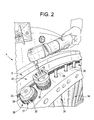
- each IGV 14 includes an airfoil portion 24 supported by a shaft member 28. Airfoil portion 24 is exposed to inlet air flow while shaft member 28 extends through compressor casing 5.
- a gear 30 is coupled to shaft member 28.
- Gear 30 includes a base portion 31 provided with a plurality of gear teeth 32. Base portion 31 extends to a raised, reduced diameter, portion 33 through a step section 34.
- Each gear 30 is operatively coupled to a ring gear 35. Rotation of ring gear 35 imparts a rotational force to IGVs 14. Over time, gear teeth 32 wear. Worn gear teeth generally lead to a need for repair or replacement of gear 30. Gear 30 completes only a partial rotation when acted upon by ring gear 35.
- a cutting tool locating device 40 is connected to gear 30 to guide a cutting tool 43 into reduced diameter portion 33.
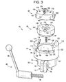
- cutting tool locating device 40 includes a base member 50, a guide member 54, a coupler member 58 and an alignment puck 62.
- Base member 50 includes a base body 70 having a lower surface 72, an upper surface 73 ( FIG. 6 ) and a central opening 75 ( FIG. 6 ).
- Lower surface 72 is configured to rest upon step section 34 with central opening 75 receiving reduced diameter portion 33.
- Base member 50 also includes a first clamping ear 78 and a second clamping ear 79. First and second clamping ears 78 and 79 are urged toward one another to secure base member 50 to reduced diameter portion 33.
- a mechanical fastener 84 is passed through an opening (not shown) in, for example, first clamping ear 78 and engages with threads (not shown) provided in an opening 85 provided in second clamping ear 79.
- Mechanical fastener 84 is shown to include a threaded portion 86 that engages with the threads and an operating handle 88.
- Base member 50 supports guide member 54.
- guide member 54 is secured to base member 50 by coupler member 58 as will be discussed more fully below. It should however be understood that guide member 54 could also be rotationally linked to base member 50.
- Guide member 54 includes a guide member body 98 having an inner surface 99 that defines a central opening 100.
- An annular step 104 extends around inner surface 99 within central opening 100.
- Guide member body 98 includes an upper surface 106 and a lower surface 107. Lower surface 107 rests upon upper surface 73 of base member 50.
- Guide member 54 is also shown to include a first flange 109 and an opposing second flange 110.
- First flange 109 includes a first portion 113 that extends generally perpendicularly from upper surface 106 and a second portion 114.
- Second portion 114 extends generally perpendicularly from first portion 113 and is spaced from upper surface 106 so as to define a first guide track 116.
- Second portion 114 is also shown to include a recess 118 having a generally circular shape.
- second flange 110 includes a first portion 122 that extends generally perpendicularly from upper surface 106 and a second portion 123.
- Second portion 123 extends generally perpendicularly from first portion 122 and is spaced from upper surface 106 so as to define a second guide track 125.
- Second portion 123 is also shown to include a recess 127 having a generally circular shape.
- Coupler member 58 includes a coupler member body 134 that is sized to be received by central opening 100.
- Coupler member body 134 includes an outer annular edge 136, an upper surface 138 and a lower surface 139 defined by an annular step portion 141.
- Annular step portion 141 is formed in outer annular edge 136.
- Coupler member body 134 includes a central opening (not separately labeled) that receives a mechanical fastener 147.
- Mechanical fastener 147 is configured to engage with a central opening (also not separately labeled) formed in shaft 28. When tightened, mechanical fastener 147 urges coupler member 58 against annular step 104 to clamp guide member 54 against upper surface 73 of base member 50.
- Coupler member body 134 also includes first and second offset openings 149 and 150 spaced from the central opening. First and second offset openings are arranged to selectively align with shaft 28 as will be discussed more fully below.
- Alignment puck 62 includes an alignment puck body 160 having a curvilinear edge 162, an upper surface 164 and a lower surface 165. Alignment puck body 160 also includes a first tab 167 and an opposing second tab 168. First and second tabs 167 and 168 are configured to be received by first and second guide tracks 116 and 125. Alignment puck 62 includes a central opening (not separately labeled) that receives a bushing 174. A fastener 176 is threaded into another opening (not shown) formed in alignment puck body 160 to retain bushing 174. Additional threaded openings 178 and 179 are positioned on either side of bushing 174. Although described as having a curvilinear edge, alignment puck 62 may include various other geometries. Further, it should be understood that instead of employing mechanical fastener 147 to claim guide member 54 to base member 50, a clamping force may be generated through fasteners extending through and operatively engaging with threaded openings 178 and 179.
- shaft 28 includes a first keyway portion 186 and gear 30 includes a second keyway portion 187.
- First and second keyway portions 186 and 187 are aligned and provided with, for example, a woodruff key to transmit movement of gear 30 to shaft 28. Over time, teeth 32 on gear 30 wear.
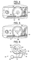
- gear 30 is rotated to expose fresh teeth (not shown) to ring gear 35 as shown in FIG. 5 .
- first and second keyway portions 186 and 187 are no longer in alignment. Accordingly, a new keyway portion is formed in gear 30.
- the new keyway portion is formed by forming an opening in gear 30 that aligns with first keyway portion 186.
- cutting tool locating device 40 is employed to form the new keyway portion.
- base member 50 is mounted to gear 30. More specifically, central opening 75 is positioned about raised, reduced diameter portion 33 with lower surface 72 resting upon step section 34.
- Mechanical fastener 84 is operated to bring together first and second clamping ears 78 and 79 to affix base member 50 to gear 30.
- guide member 54 is positioned upon upper surface 73 and coupler member 58 is positioned within central opening 100 as shown in FIG. 7 .
- Mechanical fastener 147 is threaded into the opening formed in shaft 28 to clamp guide member 54 to base member 50 as shown in FIG. 8 .
- First and second tabs 167 and 168 are aligned with first and second flanges 109 and 110 and alignment puck 62 is shifted across central opening 100 as shown in FIG. 9 .
- An alignment tool 196 is inserted into bushing 174 and guided into first keyway portion 186. Alignment tool 196 positions keyway portion 186 centrally relative to bushing 174. Alignment puck 62 may be shifted along first and second flanges 109 and 110 to facilitate insertion of alignment tool 196. Additional alignment may be provided by rotating guide member 54. Once alignment tool 196 is inserted into first keyway portion 186, mechanical fasteners 198 and 199 are threaded into threaded openings 178 and 179 and driven into contact with coupler member 58 to lock alignment puck 62 into position. At this point, cutting tool 43, such as a drill bit or the like shown in FIG.
- New keyway portion 202 includes a centerline (not separately labeled) that is substantially aligned with a centerline (also not separately labeled) of first keyway 186.
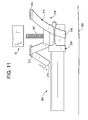
- cutting tool locating device 40 may be positioned at an underside of compressor portion 4 adjacent to a base or support structure 200 leaving little room to manipulate a tool such as shown at 204.
- Tool 204 supports and rotates a cutting tool 207 such as a drill bit or the like.
- Cutting tool 207 includes a guide element 208 that provides leverage to guide cutting tool 207 into, for example, gear 30.
- Guide element 208 includes a leveraging element 210 that takes the form of a strap 212.
- Strap 212 includes a first end 214 that extends to a second end 215 through an intermediate portion 216.
- First end 214 is affixed to, for example, compressor casing 5 and intermediate portion 216 is passed over a roller 217.
- Roller 217 is also affixed to, for example, compressor casing 5.
- a force is applied to second end 215 causing strap 212 to urge tool 204 toward compressor portion 4 guiding cutting tool 207 into gear 30 to form another keyway portion. In this manner, an operator may employ tool 204 in tighter spaces then would otherwise be possible, or comfortable.
- the alignment tool may be used to form an opening in a gear associated with any number of a variety of applications.
- the guide member may be joined directly to the base without use of a separate coupler.
Landscapes
- Engineering & Computer Science (AREA)
- Mechanical Engineering (AREA)
- General Engineering & Computer Science (AREA)
- Structures Of Non-Positive Displacement Pumps (AREA)
- Drilling And Boring (AREA)
Applications Claiming Priority (1)
| Application Number | Priority Date | Filing Date | Title |
|---|---|---|---|
| US13/658,315 US20140112727A1 (en) | 2012-10-23 | 2012-10-23 | Cutting tool locating device for forming an opening in a gear |
Publications (3)
| Publication Number | Publication Date |
|---|---|
| EP2724802A2 true EP2724802A2 (de) | 2014-04-30 |
| EP2724802A3 EP2724802A3 (de) | 2017-12-27 |
| EP2724802B1 EP2724802B1 (de) | 2020-02-12 |
Family
ID=49382273
Family Applications (1)
| Application Number | Title | Priority Date | Filing Date |
|---|---|---|---|
| EP13188540.2A Active EP2724802B1 (de) | 2012-10-23 | 2013-10-14 | Schneidwerkzeug-Lokalisierungsvorrichtung zur Bildung einer Öffnung in einem Zahnrad |
Country Status (2)
| Country | Link |
|---|---|
| US (1) | US20140112727A1 (de) |
| EP (1) | EP2724802B1 (de) |
Families Citing this family (3)
| Publication number | Priority date | Publication date | Assignee | Title |
|---|---|---|---|---|
| CN104110398A (zh) * | 2014-04-30 | 2014-10-22 | 哈尔滨汽轮机厂有限责任公司 | 一种燃气轮机压气机用的可转导叶装置 |
| EP3628647B1 (de) * | 2018-09-26 | 2020-12-02 | Benoit Pintat | Zusammensetzung zum aufbau einer dynamischen schicht eines sportbodens, sportboden und verfahren zur bereitstellung eines sportbodens |
| CN109332762B (zh) * | 2018-12-04 | 2020-06-30 | 昌乐华茂资源循环科技有限公司 | 一种电钻固定支架 |
Family Cites Families (7)
| Publication number | Priority date | Publication date | Assignee | Title |
|---|---|---|---|---|
| US820965A (en) * | 1905-12-04 | 1906-05-22 | William H Froggatt Jr | Jig for drilling, reaming, and broaching. |
| GB869924A (en) * | 1959-06-22 | 1961-06-07 | Francis Ives Wayte | Improvements in and relating to drill jigs |
| US3176548A (en) * | 1962-10-23 | 1965-04-06 | George A Pauley | Hole locating device for drilling or the like |
| US6305886B1 (en) * | 2000-06-30 | 2001-10-23 | Robert C. Womack | Drill guide fixture for drilling, to open, disc padlocks, rectangular padlocks, door knobs and lever locks |
| US6450763B1 (en) * | 2000-11-17 | 2002-09-17 | General Electric Company | Replaceable variable stator vane for gas turbines |
| GB2408471A (en) * | 2003-11-28 | 2005-06-01 | Bernard George Ryder | Jigs to form a keyway in a shaft and in a hole side-wall |
| JP5274500B2 (ja) * | 2010-03-29 | 2013-08-28 | ジヤトコ株式会社 | 歯車部品の締結治具 |
-
2012
- 2012-10-23 US US13/658,315 patent/US20140112727A1/en not_active Abandoned
-
2013
- 2013-10-14 EP EP13188540.2A patent/EP2724802B1/de active Active
Non-Patent Citations (1)
| Title |
|---|
| None |
Also Published As
| Publication number | Publication date |
|---|---|
| US20140112727A1 (en) | 2014-04-24 |
| EP2724802B1 (de) | 2020-02-12 |
| EP2724802A3 (de) | 2017-12-27 |
Similar Documents
| Publication | Publication Date | Title |
|---|---|---|
| US9988906B2 (en) | Turbomachine rotor blade milling machine system and method of field repairing a turbomachine rotor blade | |
| EP2126285B1 (de) | Sperrsystem für eine turbinenverschlussplatte | |
| US6951112B2 (en) | Methods and apparatus for assembling gas turbine engines | |
| US9523286B2 (en) | Vane segment and axial-flow fluid machine including the same | |
| EP3093436A1 (de) | Rückschnitt der zinken einer schaufel/scheibe zur belastungsreduktion der schaufel/scheibe für die zweite stufe einer turbomaschine | |
| EP2724802A2 (de) | Schneidwerkzeug-Lokalisierungsvorrichtung zur Bildung einer Öffnung in einem Zahnrad | |
| US7353588B2 (en) | Installation tool for assembling a rotor blade of a gas turbine engine fan assembly | |
| CN102220885A (zh) | 用于周向附接装置的锁定组件 | |
| CA2894032A1 (en) | Single bolting flange arrangement for variable guide vane connection | |
| CN107088591A (zh) | 用于燃气涡轮发动机的涡轮叶片的原位修理的系统及方法 | |
| US8764000B2 (en) | Tool alignment fixture | |
| EP2261567B1 (de) | Gasturbine und verfahren zum ausbilden eines einführlochs für eine gasturbinenbrennkammer | |
| JP2017074670A (ja) | ファスナ取外工具及び工具の使用方法 | |
| US10337342B2 (en) | Stator assembly for a gas turbine engine | |
| CN204212817U (zh) | 包括用于连接部件的非破坏性紧固件元件的涡轮机 | |
| KR102031963B1 (ko) | 밸런싱 플러그 셋팅툴 및 이를 이용한 밸런싱 플러그 장착 방법 | |
| JP6604600B2 (ja) | カバープレートを備えるターボ機械の構成要素 | |
| KR101967067B1 (ko) | 토크튜브 및 이를 포함하는 가스 터빈 | |
| JP4885314B1 (ja) | 管状部材固定用治具及びこれを用いた管状部材の組み立て方法 | |
| US20050172638A1 (en) | Methods and apparatus for assembling gas turbine engines | |
| US12006834B1 (en) | Gas turbine engine having a tie rod | |
| KR101979113B1 (ko) | 스페이서 조립체 및 이를 포함하는 가스 터빈 | |
| KR102480278B1 (ko) | 로터 및 이를 포함하는 터보머신 | |
| EP3088666A1 (de) | Rückschnitt der zinken einer schaufel/scheibe zur belastungsreduktion der schaufel/scheibe für die erste stufe einer turbomaschine | |
| KR20240086413A (ko) | 씰조립체를 구비하는 터빈 베인, 터빈 및 이를 포함하는 터보 머신 |
Legal Events
| Date | Code | Title | Description |
|---|---|---|---|
| PUAI | Public reference made under article 153(3) epc to a published international application that has entered the european phase |
Free format text: ORIGINAL CODE: 0009012 |
|
| 17P | Request for examination filed |
Effective date: 20131014 |
|
| AK | Designated contracting states |
Kind code of ref document: A2 Designated state(s): AL AT BE BG CH CY CZ DE DK EE ES FI FR GB GR HR HU IE IS IT LI LT LU LV MC MK MT NL NO PL PT RO RS SE SI SK SM TR |
|
| AX | Request for extension of the european patent |
Extension state: BA ME |
|
| PUAL | Search report despatched |
Free format text: ORIGINAL CODE: 0009013 |
|
| AK | Designated contracting states |
Kind code of ref document: A3 Designated state(s): AL AT BE BG CH CY CZ DE DK EE ES FI FR GB GR HR HU IE IS IT LI LT LU LV MC MK MT NL NO PL PT RO RS SE SI SK SM TR |
|
| AX | Request for extension of the european patent |
Extension state: BA ME |
|
| RIC1 | Information provided on ipc code assigned before grant |
Ipc: F01D 17/16 20060101ALI20171120BHEP Ipc: B23B 47/28 20060101AFI20171120BHEP Ipc: F01D 25/28 20060101ALI20171120BHEP |
|
| STAA | Information on the status of an ep patent application or granted ep patent |
Free format text: STATUS: REQUEST FOR EXAMINATION WAS MADE |
|
| 17P | Request for examination filed |
Effective date: 20180627 |
|
| RBV | Designated contracting states (corrected) |
Designated state(s): AL AT BE BG CH CY CZ DE DK EE ES FI FR GB GR HR HU IE IS IT LI LT LU LV MC MK MT NL NO PL PT RO RS SE SI SK SM TR |
|
| GRAP | Despatch of communication of intention to grant a patent |
Free format text: ORIGINAL CODE: EPIDOSNIGR1 |
|
| STAA | Information on the status of an ep patent application or granted ep patent |
Free format text: STATUS: GRANT OF PATENT IS INTENDED |
|
| INTG | Intention to grant announced |
Effective date: 20190621 |
|
| GRAS | Grant fee paid |
Free format text: ORIGINAL CODE: EPIDOSNIGR3 |
|
| GRAJ | Information related to disapproval of communication of intention to grant by the applicant or resumption of examination proceedings by the epo deleted |
Free format text: ORIGINAL CODE: EPIDOSDIGR1 |
|
| GRAL | Information related to payment of fee for publishing/printing deleted |
Free format text: ORIGINAL CODE: EPIDOSDIGR3 |
|
| STAA | Information on the status of an ep patent application or granted ep patent |
Free format text: STATUS: REQUEST FOR EXAMINATION WAS MADE |
|
| INTC | Intention to grant announced (deleted) | ||
| GRAR | Information related to intention to grant a patent recorded |
Free format text: ORIGINAL CODE: EPIDOSNIGR71 |
|
| STAA | Information on the status of an ep patent application or granted ep patent |
Free format text: STATUS: GRANT OF PATENT IS INTENDED |
|
| GRAA | (expected) grant |
Free format text: ORIGINAL CODE: 0009210 |
|
| STAA | Information on the status of an ep patent application or granted ep patent |
Free format text: STATUS: THE PATENT HAS BEEN GRANTED |
|
| INTG | Intention to grant announced |
Effective date: 20191206 |
|
| AK | Designated contracting states |
Kind code of ref document: B1 Designated state(s): AL AT BE BG CH CY CZ DE DK EE ES FI FR GB GR HR HU IE IS IT LI LT LU LV MC MK MT NL NO PL PT RO RS SE SI SK SM TR |
|
| REG | Reference to a national code |
Ref country code: GB Ref legal event code: FG4D |
|
| REG | Reference to a national code |
Ref country code: CH Ref legal event code: EP |
|
| REG | Reference to a national code |
Ref country code: AT Ref legal event code: REF Ref document number: 1231436 Country of ref document: AT Kind code of ref document: T Effective date: 20200215 |
|
| REG | Reference to a national code |
Ref country code: DE Ref legal event code: R096 Ref document number: 602013065642 Country of ref document: DE |
|
| REG | Reference to a national code |
Ref country code: IE Ref legal event code: FG4D |
|
| PG25 | Lapsed in a contracting state [announced via postgrant information from national office to epo] |
Ref country code: FI Free format text: LAPSE BECAUSE OF FAILURE TO SUBMIT A TRANSLATION OF THE DESCRIPTION OR TO PAY THE FEE WITHIN THE PRESCRIBED TIME-LIMIT Effective date: 20200212 Ref country code: RS Free format text: LAPSE BECAUSE OF FAILURE TO SUBMIT A TRANSLATION OF THE DESCRIPTION OR TO PAY THE FEE WITHIN THE PRESCRIBED TIME-LIMIT Effective date: 20200212 Ref country code: NO Free format text: LAPSE BECAUSE OF FAILURE TO SUBMIT A TRANSLATION OF THE DESCRIPTION OR TO PAY THE FEE WITHIN THE PRESCRIBED TIME-LIMIT Effective date: 20200512 |
|
| REG | Reference to a national code |
Ref country code: LT Ref legal event code: MG4D |
|
| REG | Reference to a national code |
Ref country code: NL Ref legal event code: MP Effective date: 20200212 |
|
| PG25 | Lapsed in a contracting state [announced via postgrant information from national office to epo] |
Ref country code: BG Free format text: LAPSE BECAUSE OF FAILURE TO SUBMIT A TRANSLATION OF THE DESCRIPTION OR TO PAY THE FEE WITHIN THE PRESCRIBED TIME-LIMIT Effective date: 20200512 Ref country code: IS Free format text: LAPSE BECAUSE OF FAILURE TO SUBMIT A TRANSLATION OF THE DESCRIPTION OR TO PAY THE FEE WITHIN THE PRESCRIBED TIME-LIMIT Effective date: 20200612 Ref country code: LV Free format text: LAPSE BECAUSE OF FAILURE TO SUBMIT A TRANSLATION OF THE DESCRIPTION OR TO PAY THE FEE WITHIN THE PRESCRIBED TIME-LIMIT Effective date: 20200212 Ref country code: SE Free format text: LAPSE BECAUSE OF FAILURE TO SUBMIT A TRANSLATION OF THE DESCRIPTION OR TO PAY THE FEE WITHIN THE PRESCRIBED TIME-LIMIT Effective date: 20200212 Ref country code: GR Free format text: LAPSE BECAUSE OF FAILURE TO SUBMIT A TRANSLATION OF THE DESCRIPTION OR TO PAY THE FEE WITHIN THE PRESCRIBED TIME-LIMIT Effective date: 20200513 Ref country code: HR Free format text: LAPSE BECAUSE OF FAILURE TO SUBMIT A TRANSLATION OF THE DESCRIPTION OR TO PAY THE FEE WITHIN THE PRESCRIBED TIME-LIMIT Effective date: 20200212 |
|
| PG25 | Lapsed in a contracting state [announced via postgrant information from national office to epo] |
Ref country code: NL Free format text: LAPSE BECAUSE OF FAILURE TO SUBMIT A TRANSLATION OF THE DESCRIPTION OR TO PAY THE FEE WITHIN THE PRESCRIBED TIME-LIMIT Effective date: 20200212 |
|
| PG25 | Lapsed in a contracting state [announced via postgrant information from national office to epo] |
Ref country code: ES Free format text: LAPSE BECAUSE OF FAILURE TO SUBMIT A TRANSLATION OF THE DESCRIPTION OR TO PAY THE FEE WITHIN THE PRESCRIBED TIME-LIMIT Effective date: 20200212 Ref country code: PT Free format text: LAPSE BECAUSE OF FAILURE TO SUBMIT A TRANSLATION OF THE DESCRIPTION OR TO PAY THE FEE WITHIN THE PRESCRIBED TIME-LIMIT Effective date: 20200705 Ref country code: DK Free format text: LAPSE BECAUSE OF FAILURE TO SUBMIT A TRANSLATION OF THE DESCRIPTION OR TO PAY THE FEE WITHIN THE PRESCRIBED TIME-LIMIT Effective date: 20200212 Ref country code: SK Free format text: LAPSE BECAUSE OF FAILURE TO SUBMIT A TRANSLATION OF THE DESCRIPTION OR TO PAY THE FEE WITHIN THE PRESCRIBED TIME-LIMIT Effective date: 20200212 Ref country code: SM Free format text: LAPSE BECAUSE OF FAILURE TO SUBMIT A TRANSLATION OF THE DESCRIPTION OR TO PAY THE FEE WITHIN THE PRESCRIBED TIME-LIMIT Effective date: 20200212 Ref country code: EE Free format text: LAPSE BECAUSE OF FAILURE TO SUBMIT A TRANSLATION OF THE DESCRIPTION OR TO PAY THE FEE WITHIN THE PRESCRIBED TIME-LIMIT Effective date: 20200212 Ref country code: LT Free format text: LAPSE BECAUSE OF FAILURE TO SUBMIT A TRANSLATION OF THE DESCRIPTION OR TO PAY THE FEE WITHIN THE PRESCRIBED TIME-LIMIT Effective date: 20200212 Ref country code: RO Free format text: LAPSE BECAUSE OF FAILURE TO SUBMIT A TRANSLATION OF THE DESCRIPTION OR TO PAY THE FEE WITHIN THE PRESCRIBED TIME-LIMIT Effective date: 20200212 Ref country code: CZ Free format text: LAPSE BECAUSE OF FAILURE TO SUBMIT A TRANSLATION OF THE DESCRIPTION OR TO PAY THE FEE WITHIN THE PRESCRIBED TIME-LIMIT Effective date: 20200212 |
|
| REG | Reference to a national code |
Ref country code: DE Ref legal event code: R097 Ref document number: 602013065642 Country of ref document: DE |
|
| REG | Reference to a national code |
Ref country code: AT Ref legal event code: MK05 Ref document number: 1231436 Country of ref document: AT Kind code of ref document: T Effective date: 20200212 |
|
| PLBE | No opposition filed within time limit |
Free format text: ORIGINAL CODE: 0009261 |
|
| STAA | Information on the status of an ep patent application or granted ep patent |
Free format text: STATUS: NO OPPOSITION FILED WITHIN TIME LIMIT |
|
| 26N | No opposition filed |
Effective date: 20201113 |
|
| PG25 | Lapsed in a contracting state [announced via postgrant information from national office to epo] |
Ref country code: IT Free format text: LAPSE BECAUSE OF FAILURE TO SUBMIT A TRANSLATION OF THE DESCRIPTION OR TO PAY THE FEE WITHIN THE PRESCRIBED TIME-LIMIT Effective date: 20200212 Ref country code: AT Free format text: LAPSE BECAUSE OF FAILURE TO SUBMIT A TRANSLATION OF THE DESCRIPTION OR TO PAY THE FEE WITHIN THE PRESCRIBED TIME-LIMIT Effective date: 20200212 |
|
| PG25 | Lapsed in a contracting state [announced via postgrant information from national office to epo] |
Ref country code: SI Free format text: LAPSE BECAUSE OF FAILURE TO SUBMIT A TRANSLATION OF THE DESCRIPTION OR TO PAY THE FEE WITHIN THE PRESCRIBED TIME-LIMIT Effective date: 20200212 Ref country code: PL Free format text: LAPSE BECAUSE OF FAILURE TO SUBMIT A TRANSLATION OF THE DESCRIPTION OR TO PAY THE FEE WITHIN THE PRESCRIBED TIME-LIMIT Effective date: 20200212 |
|
| REG | Reference to a national code |
Ref country code: CH Ref legal event code: PL |
|
| PG25 | Lapsed in a contracting state [announced via postgrant information from national office to epo] |
Ref country code: MC Free format text: LAPSE BECAUSE OF FAILURE TO SUBMIT A TRANSLATION OF THE DESCRIPTION OR TO PAY THE FEE WITHIN THE PRESCRIBED TIME-LIMIT Effective date: 20200212 Ref country code: LU Free format text: LAPSE BECAUSE OF NON-PAYMENT OF DUE FEES Effective date: 20201014 |
|
| REG | Reference to a national code |
Ref country code: BE Ref legal event code: MM Effective date: 20201031 |
|
| PG25 | Lapsed in a contracting state [announced via postgrant information from national office to epo] |
Ref country code: FR Free format text: LAPSE BECAUSE OF NON-PAYMENT OF DUE FEES Effective date: 20201031 |
|
| PG25 | Lapsed in a contracting state [announced via postgrant information from national office to epo] |
Ref country code: LI Free format text: LAPSE BECAUSE OF NON-PAYMENT OF DUE FEES Effective date: 20201031 Ref country code: CH Free format text: LAPSE BECAUSE OF NON-PAYMENT OF DUE FEES Effective date: 20201031 Ref country code: BE Free format text: LAPSE BECAUSE OF NON-PAYMENT OF DUE FEES Effective date: 20201031 |
|
| PG25 | Lapsed in a contracting state [announced via postgrant information from national office to epo] |
Ref country code: IE Free format text: LAPSE BECAUSE OF NON-PAYMENT OF DUE FEES Effective date: 20201014 |
|
| PG25 | Lapsed in a contracting state [announced via postgrant information from national office to epo] |
Ref country code: TR Free format text: LAPSE BECAUSE OF FAILURE TO SUBMIT A TRANSLATION OF THE DESCRIPTION OR TO PAY THE FEE WITHIN THE PRESCRIBED TIME-LIMIT Effective date: 20200212 Ref country code: MT Free format text: LAPSE BECAUSE OF FAILURE TO SUBMIT A TRANSLATION OF THE DESCRIPTION OR TO PAY THE FEE WITHIN THE PRESCRIBED TIME-LIMIT Effective date: 20200212 Ref country code: CY Free format text: LAPSE BECAUSE OF FAILURE TO SUBMIT A TRANSLATION OF THE DESCRIPTION OR TO PAY THE FEE WITHIN THE PRESCRIBED TIME-LIMIT Effective date: 20200212 |
|
| PG25 | Lapsed in a contracting state [announced via postgrant information from national office to epo] |
Ref country code: MK Free format text: LAPSE BECAUSE OF FAILURE TO SUBMIT A TRANSLATION OF THE DESCRIPTION OR TO PAY THE FEE WITHIN THE PRESCRIBED TIME-LIMIT Effective date: 20200212 Ref country code: AL Free format text: LAPSE BECAUSE OF FAILURE TO SUBMIT A TRANSLATION OF THE DESCRIPTION OR TO PAY THE FEE WITHIN THE PRESCRIBED TIME-LIMIT Effective date: 20200212 |
|
| REG | Reference to a national code |
Ref country code: DE Ref legal event code: R082 Ref document number: 602013065642 Country of ref document: DE Ref country code: DE Ref legal event code: R081 Ref document number: 602013065642 Country of ref document: DE Owner name: GENERAL ELECTRIC TECHNOLOGY GMBH, CH Free format text: FORMER OWNER: GENERAL ELECTRIC COMPANY, SCHENECTADY, NY, US |
|
| REG | Reference to a national code |
Ref country code: GB Ref legal event code: 732E Free format text: REGISTERED BETWEEN 20240222 AND 20240228 |
|
| PGFP | Annual fee paid to national office [announced via postgrant information from national office to epo] |
Ref country code: GB Payment date: 20250923 Year of fee payment: 13 |
|
| PGFP | Annual fee paid to national office [announced via postgrant information from national office to epo] |
Ref country code: DE Payment date: 20250923 Year of fee payment: 13 |