EP2724971B1 - Trägervorrichtung für eine aufzugshebemaschine - Google Patents
Trägervorrichtung für eine aufzugshebemaschine Download PDFInfo
- Publication number
- EP2724971B1 EP2724971B1 EP11868136.0A EP11868136A EP2724971B1 EP 2724971 B1 EP2724971 B1 EP 2724971B1 EP 11868136 A EP11868136 A EP 11868136A EP 2724971 B1 EP2724971 B1 EP 2724971B1
- Authority
- EP
- European Patent Office
- Prior art keywords
- hoisting machine
- movement
- restricting
- seat plate
- base
- Prior art date
- Legal status (The legal status is an assumption and is not a legal conclusion. Google has not performed a legal analysis and makes no representation as to the accuracy of the status listed.)
- Not-in-force
Links
Images


Classifications
-
- B—PERFORMING OPERATIONS; TRANSPORTING
- B66—HOISTING; LIFTING; HAULING
- B66B—ELEVATORS; ESCALATORS OR MOVING WALKWAYS
- B66B11/00—Main component parts of lifts in, or associated with, buildings or other structures
- B66B11/04—Driving gear ; Details thereof, e.g. seals
-
- B—PERFORMING OPERATIONS; TRANSPORTING
- B66—HOISTING; LIFTING; HAULING
- B66B—ELEVATORS; ESCALATORS OR MOVING WALKWAYS
- B66B11/00—Main component parts of lifts in, or associated with, buildings or other structures
- B66B11/0035—Arrangement of driving gear, e.g. location or support
- B66B11/004—Arrangement of driving gear, e.g. location or support in the machine room
Definitions
- the present invention relates to an elevator hoisting machine supporting apparatus, and particularly relates to a hoisting machine supporting apparatus that restricts movement of a hoisting machine during an earthquake.
- a rubber vibration isolator is inserted between a base bearing and a machine beam, a rubber vibration isolator upper plate and the base bearing are fixed by bolts, a rubber vibration isolator lower plate and the machine beam are fixed by bolts, a stopper bolt mounting seat is fixed to the rubber vibration isolator lower plate by welding, etc., so as to be positioned centrally on the rubber vibration isolator, and a stopper bolt is mounted onto the stopper bolt mounting seat so as to pass through an aperture that is formed on the base bearing (see Patent Literature 1, for example).
- Patent Literature 1 Japanese Patent Laid-Open No. SHO 58-74485 (Gazette)
- JP S54-13153 A discloses features falling under the preamble of claim 1. JP 2007/008693 A is further prior art.
- the stopper bolt mounting seat is disposed centrally on the rubber vibration isolator, making the rubber vibration isolator construction complicated, which has led to cost increases.
- the diameter of the rubber vibration isolator is increased by an amount proportionate to the aperture to ensure that damping properties are equal to a rubber vibration isolator that does not have the aperture.
- the rubber vibration isolator upper plate and lower plate are increased by an amount proportionate to the increase in the rubber vibration isolator, enlarging the supporting apparatus.
- the movement-restricting stopper bolt is a separate part from the bolts that fix the rubber vibration isolator upper plate to the base bearing, it is necessary to form the aperture through which the stopper bolt is passed on the base bearing.
- the present invention aims to solve the above problems and an object of the present invention is to provide an elevator hoisting machine supporting apparatus that enables simplification and downsizing of a rubber vibration isolator construction and that can reduce drilling for mounting on a hoisting machine base by enabling movement of the hoisting machine to be restricted using a spacer that is fixed to an upper seat plate of a rubber vibration isolator, and that connects the rubber vibration isolator and the hoisting machine base.
- an elevator hoisting machine supporting apparatus including: a rubber vibration isolator that is configured by holding a rubber material between an upper seat plate and a lower seat plate, and that is disposed by mounting the lower seat plate to a flange of a machinery base; a fastening means that fastens the lower seat plate to the flange; a cylindrical spacer of which a first end is fixed to the upper seat plate and is disposed so as to stand on the upper seat plate such that an axial direction is aligned with a center of the rubber vibration isolator, and of which a second end is fixed to a hoisting machine base; and a movement-restricting plate that has a movement-restricting aperture, and that is fixed to the lower seat plate so as to extend between the upper seat plate and the hoisting machine base such that the spacer is inserted through the movement-restricting aperture in a loosely fitted state.
- a movement-restricting aperture is formed on a movement-restricting plate that is fixed to a lower seat plate so as to extend between an upper seat plate and a hoisting machine base, and a spacer that links the upper seat plate and the hoisting machine base is inserted through the movement-restricting aperture in a loosely fitted state, to restrict movement of the hoisting machine.
- the rubber vibration isolator does not constitute a movement-restricting mechanism, the construction of the rubber vibration isolator can be simplified, enabling cost reductions and downsizing to be achieved.
- the spacer which transfers vibration of the hoisting machine to the rubber vibration isolator, serves also as a member that restricts movement of the hoisting machine by contacting an inner wall surface of the movement-restricting aperture
- an aperture for passage of a bolt to fasten the spacer is the only aperture for mounting that is formed on the hoisting machine base.
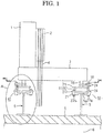
- Figure 1 is a side elevation that shows an elevator hoisting machine supporting apparatus according to Embodiment 1 of the present invention
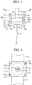
- Figure 2 is a cross section that is taken along Line II - II in Figure 1 so as to be viewed in the direction of the arrows
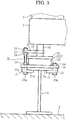
- Figure 3 is an enlargement of Portion A in Figure 1 .
- a hoisting machine 1 is fixed to a T-shaped hoisting machine base 3, and a main rope 4 that suspends a car (not shown) and a counterweight (not shown) is wound around a driving sheave 2.
- Machinery bases 5 are formed using steel H-beams, and are fixed to a floor 6 of a machine room in an upper portion of a hoistway 8 by anchor bolts (not shown) so as to be lined up parallelly.
- a first side of the T shape of the hoisting machine base 3 is mounted onto one machinery base 5, and a projecting end of a second side that projects outward from the first side is mounted onto the other machinery base 5.
- the hoisting machine base 3 is supported on the machinery bases 5 by means of supporting apparatuses 10 at three positions, namely two end portions of the first side of the T shape and a tip end portion of the second side.
- the supporting apparatuses 10 include: a rubber vibration isolator 11 that is mounted onto a flange 5a of the machinery bases 5; a fastening means that fastens the rubber vibration isolator 11 to the flange 5a; a spacer 16 that links the rubber vibration isolator 11 and the hoisting machine base 3; and a movement-restricting plate 18 that engages with the spacer 16 to restrict movement of the hoisting machine 1 due to earthquakes, etc.
- the rubber vibration isolators 11 include: a rubber material 12 that is formed into a cylindrical shape; a flat, rectangular lower seat plate 13 that is fixed to a lower surface of the rubber material 12; and a flat, circular upper seat plate 15 that is fixed to an upper surface of the rubber material 12.
- Penetrating apertures 14 for mounting are formed on four corners of the lower seat plate 13.
- the spacers 16 are formed so as to have a cylindrical shape, and are fixed to the upper seat plate 15 by welding, etc., so as to be disposed so as to stand coaxially on a central axis of the rubber material 12.
- An internal screw thread portion 17 is formed at central axial position of the spacer 16 such that a threaded aperture direction is oriented in an axial direction.
- the movement-restricting plates 18 are formed so as to have a flat, rectangular shape, and have a notch 19 that functions as a movement-restricting aperture.
- the notches 19 are formed so as to have an aperture shape that has a groove width that is greater than the diameter of the spacer 16, that has an opening centrally on an edge portion of a first side of the movement-restricting plates 18 at a first end, and that has a semicircular bottom portion at a second end.
- penetrating apertures 20 for mounting are formed at an edge portion of a side of the movement-restricting plates 18 that faces the bottom portion of the notches 19 so as to be spaced apart in a longitudinal direction of the side in question.
- Clip members 21 are formed so as to have an L shape that has a base portion 21a; and a clip portion 21b that projects outward from a first end in a thickness direction of the base portion 21a, are formed such that a penetrating aperture 22 passes through the base portion 21a in the thickness direction. Moreover, the clip members 21, mounting bolts 23a and 23b, and nuts 24 constitute the fastening means. Shaft portions of the mounting bolts 23a are longer than shaft portions of the mounting bolts 23b.
- the rubber vibration isolators 11 are mounted onto the flanges 5a of the machinery bases 5, and are fixed to the machinery bases 5 by placing the base portions 21a of the clip members 21 against lower surfaces of the four corners of the lower seat plate 13, sandwiching the flanges 5a between the lower seat plate 13 and the clip portions 21b, inserting the mounting bolts 23a and 23b into the penetrating apertures 22 that are formed on the base portions 21a of the clip members 21 and the penetrating apertures 14 that are formed on the lower seat plate 13, and securing the mounting bolts 23a and 23b and the nuts 24.
- the shaft portions of two of the mounting bolts 23a pass outside the upper seat plate 15, and extend parallelly so as to face the spacer 16.
- the movement-restricting plates 18 are fixed to the two mounting bolts 23a by passing the mounting bolts 23a through the penetrating apertures 20, positioning the center of the semicircular bottom portion of the notch 19 so as to be aligned with a central axis of the rubber vibration isolator 11, and fastening pairs of nuts 24 that are screwed onto the shaft portions of the mounting bolts 23a so as to sandwich the movement-restricting plate 18.
- the spacers 16 are thereby accommodated inside the notches 19 such that central axes thereof match the centers of the semicircular bottom portions of notches 19.
- the hoisting machine base 3 is supported on the machinery bases 5 by means of the supporting apparatuses 10 by passing mounting bolts (not shown) through penetrating apertures (not shown) that are formed on the hoisting machine base 3, and fastening them into the internal screw thread portions 17.
- the movement-restricting plates 18 of the supporting apparatuses 10 that support the two end portions of the first side of the T shape of the hoisting machine base 3 are disposed such that groove depth directions of the U shapes of the notches 19 are parallel to the direction of projection of the second side of the T shape of the hoisting machine base 3 that projects outward from the first side, and such that the openings of the notches 19 are directed toward the projecting end of the second side of the T shape of the hoisting machine base 3.
- the movement-restricting plate 18 of the supporting apparatus 10 that supports the projecting portion of the second side of the T shape of the hoisting machine base 3 is disposed such that groove depth direction of the U shape of the notch 19 is parallel to the direction of projection of the second side of the T shape of the hoisting machine base 3, and such that the opening of the notch 19 is directed toward the first side of the T shape of the hoisting machine base 3.
- the penetrating apertures 20 are formed into slots in which two ends of two parallel lines are linked by semicircles, and the movement-restricting plates 18 are fixed by the mounting bolts 23a so as to be adjusted in position such that central axes of the spacers 16 are positioned centrally in the semicircular bottom portions of the notches 19.
- vibration that is generated in the hoisting machine 1 is transferred to the rubber vibration isolators 11 by means of the hoisting machine base 3 and the spacers 16.
- the vibration is absorbed by the rubber material 12 of the rubber vibration isolators 11, preventing the vibration from propagating to the machinery bases 5.
- the members above the supporting apparatuses 10, i.e., the hoisting machine 1 that is fixed to the hoisting machine base 3 shakes significantly.
- the hoisting machine base 3 and the spacers 16 that are fixed to the hoisting machine base 3 move horizontally in synchrony with the hoisting machine 1.
- Motive force in the horizontal direction of the spacers 16 acts on the rubber material 12 by means of the upper seat plate 15, deforming the rubber material 12.
- the spacers 16 contact inner wall surfaces of the semicircular bottom portions of the notches 19 of the movement-restricting plates 18, and the motive force in the horizontal direction of the hoisting machine 1 is transferred to the machinery bases 5 by means of the spacers 16, the movement-restricting plates 18, the mounting bolts 23a, and the lower seat plates 13.
- the motive force in the horizontal direction of the hoisting machine 1 does not act to deform the rubber material 12 after the spacers 16 come into contact with the inner wall surfaces of the semicircular bottom portions of the notches 19.
- the hoisting machine 1 rotates in a horizontal plane, torque from the hoisting machine 1 acts on the rubber material 12 by means of the spacers 16 and the upper seat plates 15, deforming the rubber material 12. If the torque from the hoisting machine 1 is greater than a set value, the spacer 16 comes into contact with the inner wall surface of the semicircular bottom portion of the notch 19 in at least one supporting apparatus 10 of the supporting apparatuses 10 that support the hoisting machine base 3 at three points. Thus, the torque from the hoisting machine 1 does not act to deform the rubber material 12 after the spacer 16 comes into contact with the inner wall surface of the semicircular bottom portion of the notch 19.
- the motive force from the hoisting machine 1 acts on the rubber material 12 by means of the spacers 16 and the upper seat plates 15, deforming the rubber material 12. If the vertical motive force from the hoisting machine 1 is greater than a set value, the hoisting machine base 3 or an upper seat plate 15 contacts a movement-restricting plate 18. Thus, the motive force from the hoisting machine 1 does not act to deform the rubber material 12 after the hoisting machine base 3 or the upper seat plate 15 contacts the movement-restricting plate 18.
- the supporting apparatuses 10 can thereby restrict horizontal, vertical, and rotational movement of the hoisting machine 1.
- vibrational force such as from an earthquake acts on the hoisting machine 1, and the hoisting machine 1 moves horizontally or vertically, or rotates, because the supporting apparatuses 10 prevent the transfer of forces that would deform the rubber material 12 excessively, the amount of deformation in the rubber material 12 is suppressed, preventing situations that could lead to damage or breakage.
- situations such as the rubber material 12 deforming significantly, and being damaged or broken, and the hoisting machine 1 tipping over, can be prevented.
- the supporting apparatuses 10 constitute a movement-restricting mechanism that restricts horizontal, vertical, and rotational movement of the hoisting machine 1 using spacers 16 that are disposed so as to stand at central axial positions of the upper seat plates 15 of the rubber vibration isolators 11, and that are fixed to the hoisting machine base 3.
- the vibration-proofing mechanism and the movement-restricting mechanism are coaxial, suppressing increases in radial dimensions of the supporting apparatuses 10, and enabling downsizing.
- the present supporting apparatuses 10 are installed in place of existing supporting apparatuses that do not include a movement-restricting mechanism, situations such as the supporting apparatuses 10 interfering with the walls 7 of the machine room are prevented.
- the supporting apparatuses 10 use spacers 16 that are fixed to the upper seat plates 15 and fixed to the hoisting machine base 3 in the movement-restricting mechanism, the only bolt passage apertures that are formed on the hoisting machine base 3 in order to mount the supporting apparatuses 10 to the hoisting machine base 3 are bolt passage apertures for fastening the spacers 16.
- the present supporting apparatuses 10 are installed in place of existing supporting apparatuses that do not include a movement-restricting mechanism, the supporting apparatuses 10 can simply be installed using bolt passage apertures that are formed on the hoisting machine base 3 in order to mount the existing supporting apparatuses to the hoisting machine base 3. As a result, no additional drilling is required, improving installation workability of the supporting apparatuses 10.
- the set values of the motive force in the horizontal direction and torque in the horizontal plane at which the spacers 16 contact the wall surfaces of the bottom portions of the notches 19 can be set freely by adjusting the groove width of the notches 19, i.e., the diameter of the semicircular bottom portions.
- the set value of the vertical motive force at which the movement-restricting plates 18 contact the upper seat plates 15 or the hoisting machine base 3 can also be set freely by adjusting the gaps between the movement-restricting plates 18 and the upper seat plates 15, and the gaps between the movement-restricting plates 18 and the hoisting machine base 3.
- Embodiment 1 three points of the hoisting machine base 3 are supported on the machinery bases 5 by means of the supporting apparatuses 10, but it is not necessary to dispose the supporting apparatuses 10 at all three points of the hoisting machine base 3, and horizontal, rotational, and vertical movement can still be restricted if supporting apparatuses 10 are disposed at two points such that the groove directions of the notches 18 are in reverse directions, and a supporting apparatus that does not include a movement-restricting mechanism is disposed at a remaining point.
- the hoisting machine base is rectangular, four corners of the hoisting machine base may be supported by the machinery bases 5 by means of supporting apparatuses, but it is not necessary to use the present supporting apparatus 10 in all of the supporting apparatuses.
- Horizontal, rotational, and vertical movement can still be restricted if supporting apparatuses 10 are disposed at two points such that the groove directions of the notches 18 are in reverse directions, and supporting apparatuses that do not include a movement-restricting mechanism are disposed at two remaining points, for example.
- Figure 4 is a side elevation that shows an elevator hoisting machine supporting apparatus according to Embodiment 2 of the present invention
- Figure 5 is a cross section that is taken along Line V - V in Figure 4 so as to be viewed in the direction of the arrows.
- a rubber vibration isolator 11 is fixed to a machinery base 5 by sandwiching flanges 5a of the machinery base 5 between a lower seat plate 13 and clip portions 21b of clip members 21 at four corners of the lower seat plate 13, inserting mounting bolts 23a into penetrating apertures 22 that are formed on base portions 21a of the clip members 21 and penetrating apertures 14 that are formed on the lower seat plate 13, and securing the mounting bolts 23a and nuts 24.
- a movement-restricting plate 18A is formed so as to have a flat, rectangular shape, a circular movement-restricting aperture 25 that has a larger diameter than that of a spacer 16 is formed approximately centrally on the movement-restricting plate 18A, and penetrating apertures 14 for mounting are formed on four corners of the lower seat plate 13.
- the movement-restricting plate 18A is fixed to each of the mounting bolts 23a by passing the mounting bolts 23a through the penetrating apertures 20, positioning the center of the movement-restricting aperture 25 so as to be aligned with a central axis of the rubber vibration isolator 11, and fastening pairs of nuts 24 that are screwed onto the shaft portions of the mounting bolts 23a so as to sandwich the movement-restricting plate 18A.
- a supporting apparatus 10A that is configured in this manner, if the motive force in the horizontal direction of the hoisting machine 1 exceeds a set value, the spacer 16 also comes into contact with the inner wall surface of the movement-restricting aperture 25 of the movement-restricting plate 18A in at least one supporting apparatus 10A of supporting apparatuses 10A that support the hoisting machine base 3 at three points. If the torque in a horizontal plane of the hoisting machine 1 exceeds a set value, the spacer 16 also comes into contact with the inner wall surface of the movement-restricting aperture 25 of the movement-restricting plate 18A in at least one supporting apparatus 10A of supporting apparatuses 10A that support the hoisting machine base 3 at three points. In addition, if the vertical motive force of the hoisting machine 1 exceeds a set value, the movement-restricting plates 18A contact the upper seat plates 15 or the hoisting machine base 3.
- a supporting apparatus 10A that includes a movement-restricting mechanism in addition to a vibration-proofing mechanism can also be achieved by a simple construction, enabling similar effects to those in Embodiment 1 above to be achieved.
- Embodiment 2 because the movement-restricting plates 18A are supported by four mounting bolts 23a, the rigidity of the movement-restricting construction by the movement-restricting plates 18A is increased, enabling horizontal, vertical, and rotational movement of the hoisting machine 1 to be restricted reliably.
- Figure 6 is a side elevation that shows an elevator hoisting machine supporting apparatus according to Embodiment 3 of the present invention
- Figure 7 is a cross section that is taken along Line VII - VII in Figure 6 so as to be viewed in the direction of the arrows.
- a movement-restricting plate 18B is formed so as to have a C shape in which a movement-restricting portion 18b and a mounting portion 18c project outward from two ends of a web 18a in identical directions, a U-shaped notch 19 that has a groove width that is greater than a diameter of a spacer 16 is formed so as to have an opening at a longitudinal center of a projecting end of the movement-restricting portion 18b, and penetrating apertures 20 for mounting are formed on the mounting portion 18c so as to be separated longitudinally.
- the longitudinal direction is a direction that is perpendicular to two directions that include a facing direction between the movement-restricting portion 18b and the mounting portion 18c, and a direction of projection of the movement-restricting portion 18b and the mounting portion 18c from the web 18a.
- a movement-restricting plate 18B is fixed by fastening together with a flange 5a of a machinery base 5 by placing the mounting portion 18c against a lower seat plate 13, positioning a center of a semicircular bottom portion of the notch 19 so as to be aligned with a central axis of a rubber vibration isolator 11, and fastening nuts 24 and mounting bolts 23a that are passed through penetrating apertures 22 that are formed on base portions 21a of clip members 21, penetrating apertures 14 that are formed on the lower seat plate 13, and penetrating apertures 20 that are formed on the mounting portion 18c.
- a supporting apparatus 10B that is configured in this manner, if the motive force in the horizontal direction of the hoisting machine 1 exceeds a set value, the spacer 16 also comes into contact with the inner wall surface of the semicircular bottom portion of the notch 19 that is formed on the movement-restricting portion 18b of the movement-restricting plate 18B in at least one supporting apparatus 10B of supporting apparatuses 10B that support the hoisting machine base 3 at three points.
- the spacer 16 also comes into contact with the inner wall surface of the semicircular bottom portion of the notch 19 that is formed on the movement-restricting portion 18b of the movement-restricting plate 18B in at least one supporting apparatus 10B of supporting apparatuses 10B that support the hoisting machine base 3 at three points.
- the movement-restricting portion 18b of the movement-restricting plates 18B contact the upper seat plates 15 or the hoisting machine base 3.
- a supporting apparatus 10B that includes a movement-restricting mechanism in addition to a vibration-proofing mechanism can also be achieved by a simple construction, enabling similar effects to those in Embodiment 1 above to be achieved.
- machine bases are fixed to a floor of a machine room, but in the case of machine-roomless elevators, the machine bases are disposed so as to span across a hoistway. In other words, the machine bases are fixed to a building so as to span the hoistway.
Landscapes
- Engineering & Computer Science (AREA)
- Civil Engineering (AREA)
- Mechanical Engineering (AREA)
- Structural Engineering (AREA)
- Cage And Drive Apparatuses For Elevators (AREA)
- Lift-Guide Devices, And Elevator Ropes And Cables (AREA)
Claims (6)
- Aufzugshebemaschine-Trägervorrichtung (10), die zwischen einer Hebemaschinenbasis (3), an der eine Hebemaschine (1) befestigt ist, und einer Maschinenanlagenbasis (5) zwischengeschaltet ist, die so angeordnet ist, dass sie einen Aufzugsschacht (8) überspannt, um die Hebemaschine tragen,
wobei die Aufzugshebemaschine-Trägervorrichtung aufweist:einen Gummivibrationsisolator (11), der durch Halten eines Gummimaterials (12) zwischen einer oberen Sitzplatte (15) und einer unteren Sitzplatte (13) gestaltet ist, und der durch Anbringen der unteren Sitzplatte (13) an einem Flansch (5a) der Maschinenanlagenbasis (5) angeordnet ist;ein Befestigungsmittel, das die untere Sitzplatte (13) an dem Flansch (5a) befestigt;ein zylindrisches Distanzstück (16), dessen erstes Ende an der oberen Sitzplatte (15) befestigt ist und so angeordnet ist, dass es derart auf der oberen Sitzplatte (15) steht, dass eine axiale Richtung mit einer Mitte des Gummivibrationsisolators (11) ausgerichtet ist, und dessen zweites Ende an der Hebemaschinenbasis (3) befestigt ist; undeine Bewegungsbegrenzungsplatte (18, 18A, 18B), die eine Bewegungsbegrenzungsöffnung (19, 25) aufweist,dadurch gekennzeichnet, dassdie Bewegungsbegrenzungsplatte (18, 18A, 18B) so an der unteren Sitzplatte (13) befestigt ist, dass sie sich derart zwischen der oberen Sitzplatte (15) und der Hebemaschinenbasis (3) erstreckt, dass das Distanzstück (16) durch die Bewegungsbegrenzungsöffnung (19, 25) in einem lose gepassten Zustand eingeführt ist. - Aufzugshebemaschine-Trägervorrichtung nach Anspruch 1, dadurch gekennzeichnet, dass das Befestigungsmittel aufweist:ein Klammerelement (21), das eine L-Form ausbildet, die durch einen Basisabschnitt (21a) und einen Klammerabschnitt (21b) gebildet ist, der von einem ersten Ende des Basisabschnitts (21a) in einer Dickenrichtung nach außen vorsteht, wobei der Klammerabschnitt (21b) so angeordnet ist, dass er der unteren Sitzplatte (13) zugewandt ist, so dass der Flansch (5a) zwischengeschaltet ist;einen Befestigungsbolzen (23a, 23b), der so angebracht ist, dass er durch den Basisabschnitt (21a) und die untere Sitzplatte (13) verläuft; undeine Mutter (24), die auf den Befestigungsbolzen (23a, 23b) geschraubt ist, um die untere Sitzplatte (13) und den Flansch (5a) zu befestigen.
- Aufzugshebemaschine-Trägervorrichtung nach Anspruch 2, dadurch gekennzeichnet, dass:der Befestigungsbolzen (23a) so gestaltet ist, dass ein Wellenabschnitt außerhalb der oberen Sitzplatte (15) verläuft und sich so erstreckt, dass er dem Distanzstück (16) zugewandt ist; unddie Bewegungsbegrenzungsplatte (18, 18A) so ausgebildet ist, dass sie eine flache Form aufweist, und an dem Wellenabschnitt des Befestigungsbolzens (23a) befestigt ist, so dass sie sich zwischen der oberen Sitzplatte (15) und der Hebemaschinenbasis (3) erstreckt.
- Aufzugshebemaschine-Trägervorrichtung nach Anspruch 2, dadurch gekennzeichnet, dass die Bewegungsbegrenzungsplatte (18B) aufweist:einen Stegabschnitt (18a);einen Anbringungsabschnitt (18c), der von einem ersten Ende des Stegabschnitts (18a) in einer Richtung nach außen vorsteht, die senkrecht zu dem Stegabschnitt ist; undeinen Bewegungsbegrenzungsabschnitt (18b), der von einem zweiten Ende des Stegabschnitts (18a) in einer identischen Richtung zu dem Anbringungsabschnitt (18c) nach außen vorsteht, und an dem die Bewegungsbegrenzungsöffnung (19) ausgebildet ist;wobei der Anbringungsabschnitt (18c) zusammen mit der unteren Sitzplatte (13) durch Befestigen des Befestigungsbolzens (23a) und der Mutter (24) derart befestigt ist, dass sich der Bewegungsbegrenzungsabschnitt (18b) zwischen der oberen Sitzplatte (15) und der Hebemaschinenbasis (3) erstreckt.
- Aufzugshebemaschine-Trägervorrichtung nach einem der Ansprüche 1 bis 4, dadurch gekennzeichnet, dass die Bewegungsbegrenzungsöffnung (19) so ausgebildet ist, dass sie eine Öffnungsform aufweist, in der ein erstes Ende eine Öffnung an einem Kantenabschnitt der Bewegungsbegrenzungsplatte (18, 18B) aufweist und die einen halbkreisförmigen unteren Abschnitt an einem zweiten Ende aufweist.
- Aufzugshebemaschine-Trägervorrichtung nach einem der Ansprüche 1 bis 4, dadurch gekennzeichnet, dass die Bewegungsbegrenzungsöffnung (25) so ausgebildet ist, dass sie eine kreisförmige Öffnungsform aufweist.
Applications Claiming Priority (1)
| Application Number | Priority Date | Filing Date | Title |
|---|---|---|---|
| PCT/JP2011/064233 WO2012176287A1 (ja) | 2011-06-22 | 2011-06-22 | エレベータ用巻き上げ機の支持装置 |
Publications (3)
| Publication Number | Publication Date |
|---|---|
| EP2724971A1 EP2724971A1 (de) | 2014-04-30 |
| EP2724971A4 EP2724971A4 (de) | 2014-11-12 |
| EP2724971B1 true EP2724971B1 (de) | 2018-06-13 |
Family
ID=47422169
Family Applications (1)
| Application Number | Title | Priority Date | Filing Date |
|---|---|---|---|
| EP11868136.0A Not-in-force EP2724971B1 (de) | 2011-06-22 | 2011-06-22 | Trägervorrichtung für eine aufzugshebemaschine |
Country Status (5)
| Country | Link |
|---|---|
| EP (1) | EP2724971B1 (de) |
| JP (1) | JP5599512B2 (de) |
| KR (1) | KR101562483B1 (de) |
| CN (1) | CN103635410B (de) |
| WO (1) | WO2012176287A1 (de) |
Families Citing this family (8)
| Publication number | Priority date | Publication date | Assignee | Title |
|---|---|---|---|---|
| FR3001449B1 (fr) * | 2013-01-25 | 2019-08-16 | Moteurs Leroy-Somer | Machine d'entrainement d'un ascenseur. |
| CN106794966B (zh) * | 2014-08-25 | 2019-04-12 | 三菱电机株式会社 | 电梯用曳引机设置装置 |
| JP6600259B2 (ja) * | 2016-02-01 | 2019-10-30 | 株式会社日立製作所 | エレベータ装置 |
| JP6345374B1 (ja) * | 2016-12-22 | 2018-06-20 | 三菱電機株式会社 | エレベータ装置 |
| KR20180082245A (ko) * | 2017-01-10 | 2018-07-18 | 누리엔지 엔지니어링(주) | 엘리베이터의 전동기 지지장치 |
| JP6797100B2 (ja) * | 2017-11-16 | 2020-12-09 | 株式会社日立製作所 | 巻上機及びエレベーター |
| CN111003626B (zh) * | 2020-01-16 | 2025-05-09 | 厦门嘉达声学技术有限公司 | 曳引机隔振系统 |
| JP7450453B2 (ja) * | 2020-05-11 | 2024-03-15 | 株式会社日立製作所 | 人荷用エレベータの乗りかご |
Family Cites Families (8)
| Publication number | Priority date | Publication date | Assignee | Title |
|---|---|---|---|---|
| JPS50103046A (de) * | 1974-01-26 | 1975-08-14 | ||
| JPS559593Y2 (de) * | 1976-05-19 | 1980-03-01 | ||
| JPS5911506B2 (ja) * | 1977-06-27 | 1984-03-15 | 三菱電機株式会社 | エレベ−タ巻上機の支持装置 |
| JPS5874485A (ja) | 1981-10-26 | 1983-05-04 | 株式会社日立製作所 | エレベ−タ−駆動機械の支持装置 |
| JPH0920478A (ja) * | 1995-07-05 | 1997-01-21 | Mitsubishi Electric Corp | エレベーター機械室装置 |
| JP2002338176A (ja) * | 2001-05-17 | 2002-11-27 | Toshiba Elevator Co Ltd | 巻上機用防振体の保護機具及びその使用方法 |
| JP2007008693A (ja) * | 2005-07-01 | 2007-01-18 | Mitsubishi Electric Corp | エレベータの巻上機の支持装置 |
| CN201647772U (zh) * | 2010-01-22 | 2010-11-24 | 上海三菱电梯有限公司 | 电梯曳引机的支撑装置 |
-
2011
- 2011-06-22 EP EP11868136.0A patent/EP2724971B1/de not_active Not-in-force
- 2011-06-22 CN CN201180071703.8A patent/CN103635410B/zh not_active Expired - Fee Related
- 2011-06-22 KR KR1020147000884A patent/KR101562483B1/ko not_active Expired - Fee Related
- 2011-06-22 WO PCT/JP2011/064233 patent/WO2012176287A1/ja not_active Ceased
- 2011-06-22 JP JP2013521364A patent/JP5599512B2/ja not_active Expired - Fee Related
Non-Patent Citations (1)
| Title |
|---|
| None * |
Also Published As
| Publication number | Publication date |
|---|---|
| CN103635410A (zh) | 2014-03-12 |
| JP5599512B2 (ja) | 2014-10-01 |
| JPWO2012176287A1 (ja) | 2015-02-23 |
| EP2724971A1 (de) | 2014-04-30 |
| EP2724971A4 (de) | 2014-11-12 |
| KR101562483B1 (ko) | 2015-10-21 |
| CN103635410B (zh) | 2016-01-20 |
| KR20140035496A (ko) | 2014-03-21 |
| WO2012176287A1 (ja) | 2012-12-27 |
Similar Documents
| Publication | Publication Date | Title |
|---|---|---|
| EP2724971B1 (de) | Trägervorrichtung für eine aufzugshebemaschine | |
| US9511979B2 (en) | Underslung elevator | |
| KR101687467B1 (ko) | 엘리베이터의 권상기대 및 엘리베이터 장치 | |
| JP2015157668A (ja) | 巻上機組立体 | |
| JP2013542152A (ja) | エレベータ設備 | |
| AU2013276735B2 (en) | Lift system | |
| JP2015229570A (ja) | エレベータの巻上機設置方法および装置 | |
| JP2012153494A (ja) | エレベータ用ブレーキ装置 | |
| KR20180048785A (ko) | 가이드 레일 고정 장치 | |
| JP7217814B2 (ja) | 機械室レスエレベータの巻上機調整装置及び巻上機据付方法 | |
| JP2013047131A (ja) | エレベータ | |
| JP6704612B2 (ja) | エレベータ用ガイドレール保持装置及びこれを備えるエレベータ | |
| CN101454234B (zh) | 电梯的防振装置 | |
| JP7105906B2 (ja) | エレベーター及びコンペンロープ支持機構 | |
| AU2021394511A9 (en) | Car transport unit for a car of a passenger transport system and method for producing a shaft of a passenger transport system | |
| JP7559251B2 (ja) | 昇降路上部構造体、昇降路上部構造体の設置方法、及び、エレベーター | |
| JP7105723B2 (ja) | エレベーター及びコンペンロープ支持機構 | |
| JP2010184763A (ja) | 巻上機の耐震構造 | |
| JP6669610B2 (ja) | エレベーター及びロープ支持機構 | |
| JP2005200131A (ja) | エレベータのピット構造 | |
| JP6716038B2 (ja) | エレベータの釣合おもり装置 | |
| JP2012184081A (ja) | エレベータ装置 | |
| JP2016064921A (ja) | エレベータ装置 | |
| HK1170995A (en) | Elevator |
Legal Events
| Date | Code | Title | Description |
|---|---|---|---|
| PUAI | Public reference made under article 153(3) epc to a published international application that has entered the european phase |
Free format text: ORIGINAL CODE: 0009012 |
|
| 17P | Request for examination filed |
Effective date: 20131209 |
|
| AK | Designated contracting states |
Kind code of ref document: A1 Designated state(s): AL AT BE BG CH CY CZ DE DK EE ES FI FR GB GR HR HU IE IS IT LI LT LU LV MC MK MT NL NO PL PT RO RS SE SI SK SM TR |
|
| DAX | Request for extension of the european patent (deleted) | ||
| A4 | Supplementary search report drawn up and despatched |
Effective date: 20141010 |
|
| RIC1 | Information provided on ipc code assigned before grant |
Ipc: B66B 11/00 20060101ALI20141006BHEP Ipc: B66B 11/04 20060101AFI20141006BHEP |
|
| GRAP | Despatch of communication of intention to grant a patent |
Free format text: ORIGINAL CODE: EPIDOSNIGR1 |
|
| INTG | Intention to grant announced |
Effective date: 20180209 |
|
| GRAS | Grant fee paid |
Free format text: ORIGINAL CODE: EPIDOSNIGR3 |
|
| GRAA | (expected) grant |
Free format text: ORIGINAL CODE: 0009210 |
|
| AK | Designated contracting states |
Kind code of ref document: B1 Designated state(s): AL AT BE BG CH CY CZ DE DK EE ES FI FR GB GR HR HU IE IS IT LI LT LU LV MC MK MT NL NO PL PT RO RS SE SI SK SM TR |
|
| REG | Reference to a national code |
Ref country code: GB Ref legal event code: FG4D |
|
| REG | Reference to a national code |
Ref country code: CH Ref legal event code: EP Ref country code: AT Ref legal event code: REF Ref document number: 1008298 Country of ref document: AT Kind code of ref document: T Effective date: 20180615 |
|
| REG | Reference to a national code |
Ref country code: IE Ref legal event code: FG4D |
|
| REG | Reference to a national code |
Ref country code: DE Ref legal event code: R096 Ref document number: 602011049332 Country of ref document: DE |
|
| REG | Reference to a national code |
Ref country code: NL Ref legal event code: MP Effective date: 20180613 |
|
| REG | Reference to a national code |
Ref country code: LT Ref legal event code: MG4D |
|
| PG25 | Lapsed in a contracting state [announced via postgrant information from national office to epo] |
Ref country code: NO Free format text: LAPSE BECAUSE OF FAILURE TO SUBMIT A TRANSLATION OF THE DESCRIPTION OR TO PAY THE FEE WITHIN THE PRESCRIBED TIME-LIMIT Effective date: 20180913 Ref country code: FI Free format text: LAPSE BECAUSE OF FAILURE TO SUBMIT A TRANSLATION OF THE DESCRIPTION OR TO PAY THE FEE WITHIN THE PRESCRIBED TIME-LIMIT Effective date: 20180613 Ref country code: BG Free format text: LAPSE BECAUSE OF FAILURE TO SUBMIT A TRANSLATION OF THE DESCRIPTION OR TO PAY THE FEE WITHIN THE PRESCRIBED TIME-LIMIT Effective date: 20180913 Ref country code: LT Free format text: LAPSE BECAUSE OF FAILURE TO SUBMIT A TRANSLATION OF THE DESCRIPTION OR TO PAY THE FEE WITHIN THE PRESCRIBED TIME-LIMIT Effective date: 20180613 Ref country code: CY Free format text: LAPSE BECAUSE OF FAILURE TO SUBMIT A TRANSLATION OF THE DESCRIPTION OR TO PAY THE FEE WITHIN THE PRESCRIBED TIME-LIMIT Effective date: 20180613 Ref country code: ES Free format text: LAPSE BECAUSE OF FAILURE TO SUBMIT A TRANSLATION OF THE DESCRIPTION OR TO PAY THE FEE WITHIN THE PRESCRIBED TIME-LIMIT Effective date: 20180613 Ref country code: SE Free format text: LAPSE BECAUSE OF FAILURE TO SUBMIT A TRANSLATION OF THE DESCRIPTION OR TO PAY THE FEE WITHIN THE PRESCRIBED TIME-LIMIT Effective date: 20180613 |
|
| PG25 | Lapsed in a contracting state [announced via postgrant information from national office to epo] |
Ref country code: LV Free format text: LAPSE BECAUSE OF FAILURE TO SUBMIT A TRANSLATION OF THE DESCRIPTION OR TO PAY THE FEE WITHIN THE PRESCRIBED TIME-LIMIT Effective date: 20180613 Ref country code: HR Free format text: LAPSE BECAUSE OF FAILURE TO SUBMIT A TRANSLATION OF THE DESCRIPTION OR TO PAY THE FEE WITHIN THE PRESCRIBED TIME-LIMIT Effective date: 20180613 Ref country code: RS Free format text: LAPSE BECAUSE OF FAILURE TO SUBMIT A TRANSLATION OF THE DESCRIPTION OR TO PAY THE FEE WITHIN THE PRESCRIBED TIME-LIMIT Effective date: 20180613 Ref country code: GR Free format text: LAPSE BECAUSE OF FAILURE TO SUBMIT A TRANSLATION OF THE DESCRIPTION OR TO PAY THE FEE WITHIN THE PRESCRIBED TIME-LIMIT Effective date: 20180914 |
|
| REG | Reference to a national code |
Ref country code: AT Ref legal event code: MK05 Ref document number: 1008298 Country of ref document: AT Kind code of ref document: T Effective date: 20180613 |
|
| PG25 | Lapsed in a contracting state [announced via postgrant information from national office to epo] |
Ref country code: NL Free format text: LAPSE BECAUSE OF FAILURE TO SUBMIT A TRANSLATION OF THE DESCRIPTION OR TO PAY THE FEE WITHIN THE PRESCRIBED TIME-LIMIT Effective date: 20180613 |
|
| PG25 | Lapsed in a contracting state [announced via postgrant information from national office to epo] |
Ref country code: IS Free format text: LAPSE BECAUSE OF FAILURE TO SUBMIT A TRANSLATION OF THE DESCRIPTION OR TO PAY THE FEE WITHIN THE PRESCRIBED TIME-LIMIT Effective date: 20181013 Ref country code: PL Free format text: LAPSE BECAUSE OF FAILURE TO SUBMIT A TRANSLATION OF THE DESCRIPTION OR TO PAY THE FEE WITHIN THE PRESCRIBED TIME-LIMIT Effective date: 20180613 Ref country code: SK Free format text: LAPSE BECAUSE OF FAILURE TO SUBMIT A TRANSLATION OF THE DESCRIPTION OR TO PAY THE FEE WITHIN THE PRESCRIBED TIME-LIMIT Effective date: 20180613 Ref country code: CZ Free format text: LAPSE BECAUSE OF FAILURE TO SUBMIT A TRANSLATION OF THE DESCRIPTION OR TO PAY THE FEE WITHIN THE PRESCRIBED TIME-LIMIT Effective date: 20180613 Ref country code: RO Free format text: LAPSE BECAUSE OF FAILURE TO SUBMIT A TRANSLATION OF THE DESCRIPTION OR TO PAY THE FEE WITHIN THE PRESCRIBED TIME-LIMIT Effective date: 20180613 Ref country code: AT Free format text: LAPSE BECAUSE OF FAILURE TO SUBMIT A TRANSLATION OF THE DESCRIPTION OR TO PAY THE FEE WITHIN THE PRESCRIBED TIME-LIMIT Effective date: 20180613 Ref country code: EE Free format text: LAPSE BECAUSE OF FAILURE TO SUBMIT A TRANSLATION OF THE DESCRIPTION OR TO PAY THE FEE WITHIN THE PRESCRIBED TIME-LIMIT Effective date: 20180613 |
|
| REG | Reference to a national code |
Ref country code: CH Ref legal event code: PL |
|
| PG25 | Lapsed in a contracting state [announced via postgrant information from national office to epo] |
Ref country code: SM Free format text: LAPSE BECAUSE OF FAILURE TO SUBMIT A TRANSLATION OF THE DESCRIPTION OR TO PAY THE FEE WITHIN THE PRESCRIBED TIME-LIMIT Effective date: 20180613 Ref country code: IT Free format text: LAPSE BECAUSE OF FAILURE TO SUBMIT A TRANSLATION OF THE DESCRIPTION OR TO PAY THE FEE WITHIN THE PRESCRIBED TIME-LIMIT Effective date: 20180613 |
|
| REG | Reference to a national code |
Ref country code: BE Ref legal event code: MM Effective date: 20180630 |
|
| REG | Reference to a national code |
Ref country code: DE Ref legal event code: R097 Ref document number: 602011049332 Country of ref document: DE |
|
| REG | Reference to a national code |
Ref country code: IE Ref legal event code: MM4A |
|
| PG25 | Lapsed in a contracting state [announced via postgrant information from national office to epo] |
Ref country code: LU Free format text: LAPSE BECAUSE OF NON-PAYMENT OF DUE FEES Effective date: 20180622 Ref country code: MC Free format text: LAPSE BECAUSE OF FAILURE TO SUBMIT A TRANSLATION OF THE DESCRIPTION OR TO PAY THE FEE WITHIN THE PRESCRIBED TIME-LIMIT Effective date: 20180613 |
|
| PLBE | No opposition filed within time limit |
Free format text: ORIGINAL CODE: 0009261 |
|
| STAA | Information on the status of an ep patent application or granted ep patent |
Free format text: STATUS: NO OPPOSITION FILED WITHIN TIME LIMIT |
|
| PG25 | Lapsed in a contracting state [announced via postgrant information from national office to epo] |
Ref country code: LI Free format text: LAPSE BECAUSE OF NON-PAYMENT OF DUE FEES Effective date: 20180630 Ref country code: IE Free format text: LAPSE BECAUSE OF NON-PAYMENT OF DUE FEES Effective date: 20180622 Ref country code: CH Free format text: LAPSE BECAUSE OF NON-PAYMENT OF DUE FEES Effective date: 20180630 |
|
| 26N | No opposition filed |
Effective date: 20190314 |
|
| GBPC | Gb: european patent ceased through non-payment of renewal fee |
Effective date: 20180913 |
|
| PG25 | Lapsed in a contracting state [announced via postgrant information from national office to epo] |
Ref country code: SI Free format text: LAPSE BECAUSE OF FAILURE TO SUBMIT A TRANSLATION OF THE DESCRIPTION OR TO PAY THE FEE WITHIN THE PRESCRIBED TIME-LIMIT Effective date: 20180613 Ref country code: DK Free format text: LAPSE BECAUSE OF FAILURE TO SUBMIT A TRANSLATION OF THE DESCRIPTION OR TO PAY THE FEE WITHIN THE PRESCRIBED TIME-LIMIT Effective date: 20180613 Ref country code: BE Free format text: LAPSE BECAUSE OF NON-PAYMENT OF DUE FEES Effective date: 20180630 |
|
| PG25 | Lapsed in a contracting state [announced via postgrant information from national office to epo] |
Ref country code: FR Free format text: LAPSE BECAUSE OF NON-PAYMENT OF DUE FEES Effective date: 20180813 |
|
| PG25 | Lapsed in a contracting state [announced via postgrant information from national office to epo] |
Ref country code: GB Free format text: LAPSE BECAUSE OF NON-PAYMENT OF DUE FEES Effective date: 20180913 |
|
| PG25 | Lapsed in a contracting state [announced via postgrant information from national office to epo] |
Ref country code: AL Free format text: LAPSE BECAUSE OF FAILURE TO SUBMIT A TRANSLATION OF THE DESCRIPTION OR TO PAY THE FEE WITHIN THE PRESCRIBED TIME-LIMIT Effective date: 20180613 |
|
| PG25 | Lapsed in a contracting state [announced via postgrant information from national office to epo] |
Ref country code: MT Free format text: LAPSE BECAUSE OF NON-PAYMENT OF DUE FEES Effective date: 20180622 |
|
| PG25 | Lapsed in a contracting state [announced via postgrant information from national office to epo] |
Ref country code: TR Free format text: LAPSE BECAUSE OF FAILURE TO SUBMIT A TRANSLATION OF THE DESCRIPTION OR TO PAY THE FEE WITHIN THE PRESCRIBED TIME-LIMIT Effective date: 20180613 |
|
| PG25 | Lapsed in a contracting state [announced via postgrant information from national office to epo] |
Ref country code: PT Free format text: LAPSE BECAUSE OF FAILURE TO SUBMIT A TRANSLATION OF THE DESCRIPTION OR TO PAY THE FEE WITHIN THE PRESCRIBED TIME-LIMIT Effective date: 20180613 Ref country code: HU Free format text: LAPSE BECAUSE OF FAILURE TO SUBMIT A TRANSLATION OF THE DESCRIPTION OR TO PAY THE FEE WITHIN THE PRESCRIBED TIME-LIMIT; INVALID AB INITIO Effective date: 20110622 |
|
| PG25 | Lapsed in a contracting state [announced via postgrant information from national office to epo] |
Ref country code: MK Free format text: LAPSE BECAUSE OF NON-PAYMENT OF DUE FEES Effective date: 20180613 |
|
| PGFP | Annual fee paid to national office [announced via postgrant information from national office to epo] |
Ref country code: DE Payment date: 20200609 Year of fee payment: 10 |
|
| REG | Reference to a national code |
Ref country code: DE Ref legal event code: R119 Ref document number: 602011049332 Country of ref document: DE |
|
| PG25 | Lapsed in a contracting state [announced via postgrant information from national office to epo] |
Ref country code: DE Free format text: LAPSE BECAUSE OF NON-PAYMENT OF DUE FEES Effective date: 20220101 |