EP2725439A2 - Automatic machining path generation - Google Patents
Automatic machining path generation Download PDFInfo
- Publication number
- EP2725439A2 EP2725439A2 EP13005114.7A EP13005114A EP2725439A2 EP 2725439 A2 EP2725439 A2 EP 2725439A2 EP 13005114 A EP13005114 A EP 13005114A EP 2725439 A2 EP2725439 A2 EP 2725439A2
- Authority
- EP
- European Patent Office
- Prior art keywords
- processing
- calculation unit
- area
- divided
- processing machine
- Prior art date
- Legal status (The legal status is an assumption and is not a legal conclusion. Google has not performed a legal analysis and makes no representation as to the accuracy of the status listed.)
- Granted
Links
Images






Classifications
-
- G—PHYSICS
- G05—CONTROLLING; REGULATING
- G05B—CONTROL OR REGULATING SYSTEMS IN GENERAL; FUNCTIONAL ELEMENTS OF SUCH SYSTEMS; MONITORING OR TESTING ARRANGEMENTS FOR SUCH SYSTEMS OR ELEMENTS
- G05B19/00—Program-control systems
- G05B19/02—Program-control systems electric
- G05B19/18—Numerical control [NC], i.e. automatically operating machines, in particular machine tools, e.g. in a manufacturing environment, so as to execute positioning, movement or co-ordinated operations by means of program data in numerical form
- G05B19/4093—Numerical control [NC], i.e. automatically operating machines, in particular machine tools, e.g. in a manufacturing environment, so as to execute positioning, movement or co-ordinated operations by means of program data in numerical form characterised by part programming, e.g. entry of geometrical information as taken from a technical drawing, combining this with machining and material information to obtain control information, named part program, for the NC machine
- G05B19/40931—Numerical control [NC], i.e. automatically operating machines, in particular machine tools, e.g. in a manufacturing environment, so as to execute positioning, movement or co-ordinated operations by means of program data in numerical form characterised by part programming, e.g. entry of geometrical information as taken from a technical drawing, combining this with machining and material information to obtain control information, named part program, for the NC machine concerning programming of geometry
- G05B19/40932—Shape input
-
- Y—GENERAL TAGGING OF NEW TECHNOLOGICAL DEVELOPMENTS; GENERAL TAGGING OF CROSS-SECTIONAL TECHNOLOGIES SPANNING OVER SEVERAL SECTIONS OF THE IPC; TECHNICAL SUBJECTS COVERED BY FORMER USPC CROSS-REFERENCE ART COLLECTIONS [XRACs] AND DIGESTS
- Y02—TECHNOLOGIES OR APPLICATIONS FOR MITIGATION OR ADAPTATION AGAINST CLIMATE CHANGE
- Y02P—CLIMATE CHANGE MITIGATION TECHNOLOGIES IN THE PRODUCTION OR PROCESSING OF GOODS
- Y02P90/00—Enabling technologies with a potential contribution to greenhouse gas [GHG] emissions mitigation
- Y02P90/02—Total factory control, e.g. smart factories, flexible manufacturing systems [FMS] or integrated manufacturing systems [IMS]
Definitions
- the present invention relates to a process schedule support apparatus, a process schedule support program, and a process schedule support method.
- Japanese Patent Laid-open Publication No. H04-372002 includes the description that reads "...has an object to efficiently produce a control operation program for a production line by expressing inputs, intermediate processing data, and results handled in a process design upstream of a production activity so as to be easily converted into a data format required in a production scheduling system and a production preparation work support system such as an NC automatic programming system, and integrating production scheduling and production information preparation work based on processing results of the process design.”
- a processing process is planned based on empirical knowledge of a CAM operator in an enormous number of combinations of selection/arrangement setting of tools/processing machines, processing area setting, and processing condition setting, and hence a processing time for a processing process plan may vary, instead of becoming shortest, depending on a degree of the CAM operator's experience.
- the technology disclosed in Japanese Patent Laid-open Publication No. H04-372002 is a technology for calling information from a database in which NC data is registered manually in advance. Therefore, there are cases where the registered information may not be optimal depending on a degree of the experience of a person who registers information in the database, and the NC data created by using the database may not also be optimal.
- the present invention has been made in view of the above-mentioned circumstances, and an object of the present invention is to allow an optimal work procedure using a processing machine to be automatically generated irrespective of whether or not an operator has experience relating thereto.
- the present application incudes a plurality of means for achieving the above-mentioned object, but one example thereof is a process schedule support apparatus, which supports creation of control data on a processing machine, including:
- the optimal work procedure using the processing machine may be automatically generated irrespective of whether or not the operator has experience relating thereto.
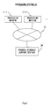
- FIG. 1 is a system configuration diagram illustrating an example of a functional configuration of a processing system 10 according to an embodiment of the present invention.
- the processing system 10 includes a process schedule support apparatus 20 and a plurality of processing machines 11-1, 11-2, and the like (hereinafter referred to collectively as "11").
- the process schedule support apparatus 20 and each of the processing machines 11 are connected to a communication line 12, and can communicate to/from one another through the communication line 12.
- FIG. 2 is a block diagram illustrating an example of a functional configuration of the process schedule support apparatus 20 according to the first embodiment of the present invention.
- the process schedule support apparatus 20 includes a storage unit 21, a removal area calculation unit 22, a divided area calculation unit 23, a tool path calculation unit 24, a processing time calculation unit 25, and a calculation result output unit 26.
- the storage unit 21 stores processing machine data 210, tool data 211, processing machine condition data 212, product CAD data 213, and material CAD data 214.
- FIG. 3 is a conceptual diagram showing an example of the processing machine data 210 stored in the storage unit 21.
- the processing machine data 210 stores in advance a processing machine name 2101, an axis configuration 2102, a setup time 2103, and the like in association withaprocessingmachine ID 2100 which identifies each processing machine. Further, the processing machine ID 2100 stores in advance a stroke 2104, an arrangement time 2105, and the like for each of axes of the axis configuration 2102.
- FIG. 4 is a conceptual diagram showing an example of the tool data 211 stored in the storage unit 21.
- the tool data 211 stores in advance a processing machine ID 2111 of the processing machine to which the tool is to be mounted, a tool diameter 2112, a tool tip radius 2113, a tool length 2114, a holder diameter 2115, a holder length 2116, and the like in association with a tool ID 2110 which identifies each tool.
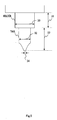
- FIG. 5 is a conceptual diagram for illustrating an example of respective dimensions of a tool and a holder.
- the tool diameter 2112 represents, for example, a dimension indicated by reference numeral 32
- the tool tip radius 2113 represents, for example, a dimension indicated by reference numeral 34
- the tool length 2114 represents, for example, a dimension indicated by reference numeral 33
- the holder diameter 2115 represents, for example, a dimension indicated by reference numeral 30
- the holder length 2116 represents, for example, a dimension indicated by reference numeral 31.
- FIG. 6 is a conceptual diagram showing an example of the processing machine condition data 212 stored in the storage unit 21.
- the processing machine condition data 212 stores in advance a condition table 2121 in association with a material ID 2120 which identifies each material.
- Each condition table 2121 stores in advance a tool ID 2123 of the tool to be used, a number of revolutions 2124, a feed rate 2125, a feed per tooth 2126, a cutting speed 2127, an axial cutting 2128, and a radial cutting 2129 in association with a condition ID 2122 which identifies each processing condition.
- FIG. 7 is a conceptual diagram showing an example of the product CAD data 213 stored in the storage unit 21.
- the product CAD data 213 stores in advance CAD data 2131 which indicates a shape of the product as illustrated in, for example, FIG. 10A and a material ID 2132 of a material used to process the product in association with a product ID 2130 which identifies each product.
- FIG. 8 is a conceptual diagram showing an example of the material CAD data 214 stored in the storage unit 21.
- the material CAD data 214 stores in advance CAD data 2141 which indicates a shape of the material as illustrated in, for example, FIG. 10B in association with a material ID 2140 which identifies each material.
- the removal area calculation unit 22 refers to the CAD data within the product CAD data 213 foreachproduct, and uses information on a characteristic flat plane (face plane) included in the CAD data to create an arrangement plane for each processing machine fromaplane indicating a boundary between an area in which the product is grasped by the processing machine when being processed and an area in which the product may be processed by the processing machine.
- face plane characteristic flat plane
- FIG. 9 is a conceptual diagram for illustrating an example of an arrangement plane 400 and an arrangement plane 401.
- the removal area calculation unit 22 calculates, for example, the arrangement plane 400 and the arrangement plane 401 as the arrangement planes from the CAD data on a product shape 40.
- FIGS. 10A to 10C are conceptual diagrams for illustrating a process of calculating a removal area 42.
- the removal area calculation unit 22 then, for each product, extracts the CAD data on a product shape from the product CAD data 213, and extracts the CAD data on a material used to process the product from the material CAD data 214. Then, the removal area calculation unit 22 uses those pieces of CAD data to calculate the removal area 42 as illustrated in, for example, FIG. 10C indicating an area to be removed from a difference between the product shape 40 as illustrated in, for example, FIG. 10A and a material shape 41 as illustrated in, for example, FIG. 10B . Then, the removal area calculation unit 22 sends the removal area 42 calculated for each product to the divided area calculation unit 23.
- the divided area calculation unit 23 refers to the processing machine data 210 for each removal area 42 of the product, and calculates the arrangement plane from a plane (which does not need to be flat plane) which defines a limit to a movable range of each processing machine. Then, the divided area calculation unit 23 divides the removal area 42 by the arrangement plane calculated for each processing machine, to create a divided area.
- FIG. 11 is a conceptual diagram for illustrating an example of a method of dividing the removal area 42.
- an arrangement plane 420, an arrangement plane 421, an arrangement plane 422, and an arrangement plane 423 are separately calculated for a plurality of processing machines, and the removal area 42 is divided by those calculated planes.
- the removal area 42 is thus divided by the plane that defines the limit to the movable range of each processing machine, and hence, for each divided area, at least one processing machine that may completely remove the each divided area always exists.
- the divided area calculation unit 23 calculates four arrangement planes at intervals of, for example, 90 degrees in order to speed up the processing.
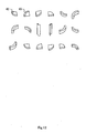
- FIG. 12 is a conceptual diagram for illustrating an example of a divided area 43.
- the removal area 42 is divided by a plurality of arrangement planes as illustrated in FIG. 11 , to thereby generate a plurality of divided areas 43 by the divided area calculation unit 23 as illustrated in FIG. 12 .
- the divided area calculation unit 23 sends information on each of the divided areas 43 generated for each product to the tool path calculation unit 24.
- the tool path calculation unit 24 refers to the processing machine data 210 and the tool data 211 for each of the divided areas 43 calculated for each product, to generate a tool path being a locus of the tool for removing the divided area 43 for each processing machine. For one of the divided areas 43, one tool path for each of all the processing machines is calculated. Then, the tool path calculation unit 24 sends data on the tool paths, which are calculated for each of the divided areas 43 to be used by the respective processing machines, to the processing time calculation unit 25 for each product.
- the processing time calculation unit 25 refers to the product CAD data 213, to identify a material ID of the material used to process the product for each product. Then, the processing time calculation unit 25 identifies the condition table 2121 within the processing machine condition data 212 based on the identified material ID.
- the processing time calculation unit 25 refers to the tool data 211 for each processing machine, to identify a tool ID of the tool used by the each processing machine. Then, for each combination of the product and the divided area 43, the processing time calculation unit 25 refers to the condition table 2121 for the tool of each processing machine, to extract the processing condition to be applied in a case where the tool is used. Then, the processing time calculation unit 25 calculates the processing time, which is to be required in a case where the tool is moved along the tool path based on the length of the tool path calculated by the tool path calculation unit 24 on the extracted processing condition, for each combination of the product, the divided area 43, and the processing machine.
- the processing time calculation unit 25 uses information on all the processing times calculated for each combination of the product, the divided area 43, and the processing machine, to calculate, for each product, a combination of the processing times for each of the divided areas 43 which has the minimum total processing time.
- the processing time calculation unit 25 obtains a total processing time L as, for example, mixed integer programming problems expressed by the following Mathematical Expressions 1 to 9 by, for example, a branch-and-bound method.
- Mathematical Expression 2 and Mathematical Expression 3 indicate that a processing process is carried out by the selected arrangement plane and by the selected processing machine.
- Mathematical Expression 4 and Mathematical Expression 5 indicate that the processing process is carried out at most one processing machine with at most one grasp.
- Mathematical Expression 6 indicates that the divided area needs to be removed in one-time processing performed by any one of the processing machines.
- Mathematical Expression 7 indicates that the divided areas, which are continuously processed, are adjacent to each other.
- Mathematical Expression 8 indicates a definition of the total processing time L for the processing process plan.
- Mathematical Expression 9 indicates a value range of the variable.
- the processing time calculation unit 25 sends the minimum total processing time L calculated for each product by using the above-mentioned Mathematical Expressions 1 to 9, the processing times for the respective divided areas included in the total processing time L, and process numbers indicating an order of processing the respective divided areas to the calculation result output unit 26, and sends the data on the tool paths for each of the divided area, which achieve the minimum total processing time L, to a data setting unit 27 for each product.
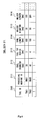
- the calculation result output unit 26 creates a result display screen 50 as illustrated in, for example, FIG. 13 , and displays the result display screen 50 on a display device 200.
- FIG. 13 is a conceptual diagram for illustrating an example of the result display screen 50.
- Processing information 52 is displayed on the result display screen 50 for each product ID 51.
- Each piece of processing information 52 is provided with an area 53 in which a shape of the divided area is displayed for each area ID identifying each divided area.
- a user is allowed to confirm the shapes of all the divided areas by operating a slider 54 through the input device 201.
- each piece of processing information 52 is provided with an area 55 in which the total processing time calculated by the processing time calculation unit 25 is displayed, below which a processing time table 56 showing a breakdown of the total processing time is displayed.
- the processing time table 56 includes an area ID 561 of the divided area to be removed in the processing process, a processing machine name 562 of the processing machine used to remove the divided area, and a processing time 563 required to remove the divided area, and the like in association with a process number 560 indicating the order of the respectiveprocessingprocesses.
- the user is allowed to refer to those pieces of information for all the process numbers by operating a slider 564 through the input device 201.
- the data setting unit 27 transfers the data on the tool paths for each of the divided areas calculated for the product having the product ID 51 to the processing machine used to process the divided area through the communication line 12 based on the product ID 51 of the processing information 52 including the pressed "execute" button 565.
- FIG. 14 is a flowchart illustrating an example of an operation of the process schedule support apparatus 20.
- the process schedule support apparatus 20 starts the operation illustrated in this flowchart when, for example, receiving an instruction from the user through the input device 201.
- the removal area calculation unit 22 refers to the product CAD data 213 to select one unselected product ID (S100). Then, the removal area calculation unit 22 extracts the CAD data associated with the selected product ID from the product CAD data 213, and uses information on a characteristic flat plane included in the CAD data to calculate the arrangement plane indicating a boundary between the area in which the product is grasped by the processing machine when being processed and the area in which the product may be processed by the processing machine (S101).
- the removal area calculation unit 22 extracts the material ID associated with the product ID selected in S100 from the product CAD data 213, and extracts the CAD data associated with the extracted material ID from the material CAD data 214. Then, the removal area calculation unit 22 uses those pieces of CAD data to calculate a removal area indicating the area to be removed from a difference between the product shape and a material shape as illustrated in FIG. 10C (S102), and sends the information on the calculated removal area to the divided area calculation unit 23.
- the divided area calculation unit 23 refers to the processing machine data 210 for each processing machine, to calculate the arrangement plane from the plane which defines a limit to the movable range of each processing machine. Then, the divided area calculation unit 23 divides the removal area by the arrangement plane calculated for each processing machine, to calculate the divided area (S103), and sends the information on each of the calculated divided areas to the tool path calculation unit 24.
- the tool path calculation unit 24 selects one unselected divided area among the divided areas received from the divided area calculation unit 23 (S104). Then, the tool path calculation unit 24 refers to the processing machine data 210 to select one unselected processing machine (S105), refers to the tool data 211 on the selected processing machine to generate the tool path being a locus of the tool for removing the divided area selected in Step S104, and sends the data on the generated tool path to the processing time calculation unit 25.
- the processing time calculation unit 25 refers to the tool data 211 on the processing machine selected in Step S105 to identify the tool ID of the tool used by the processing machine, and extracts the processing condition to be applied in the case where the tool is used from the processing machine condition data 212. Then, the processing time calculation unit 25 calculates the processing time to be required in the case where the tool is moved along the tool path based on the length of the tool path generated by the tool path calculation unit 24 on the extracted processing condition (S106).
- the tool path calculation unit 24 refers to the processing machine data 210 to determine whether or not all the processing machines have been selected (S107). If there is an unselectedprocessingmachine (No in S107), the tool path calculation unit 24 again executes the processing illustrated in Step S105. On the other hand, if all the processing machines have been selected (Yes in S107), the tool path calculation unit 24 determines whether or not all the divided areas have been selected (S108). If there is an unselected divided area (No in S108), the tool path calculation unit 24 again executes the processing illustrated in Step S104.
- the processing time calculation unit 25 uses the information on all the processing times calculated for each combination of the divided area and the processing machine, to calculate a combination of the processing times which has the minimum total processing time L as, for example, the mixed integer programming problems expressed by the above-mentioned Mathematical Expressions 1 to 9 by, for example, the branch-and-bound method (S109), and sends those calculated pieces of information to the calculation result output unit 26.
- the removal area calculation unit 22 refers to the product CAD data 213 to determine whether or not all the product IDs have been selected (S110). If there is an unselected product ID (No in S110), the removal area calculation unit 22 again executes the processing illustrated in Step S100. On the other hand, if all the product IDs have been selected (Yes in S110), based on the information received from the processing time calculation unit 25, the calculation result output unit 26 creates the result display screen 50 described with reference to, for example, FIG. 13 , and displays the result display screen 50 on the display device 200 (S111).
- the data setting unit 27 transfers the data on the tool path to each of the processing machines 11 through the communication line 12 (S112), and the process schedule support apparatus 20 finishes the operation illustrated in the flowchart.
- FIG. 15 is a block diagram illustrating an example of a functional configuration of the process schedule support apparatus 20 according to the second embodiment. Note that, except for points described below, in FIG. 15 , components denoted by the same reference numerals as those in FIG. 2 have the same or similar functions as/to the components illustrated in FIG. 2 , and hence descriptions thereof are omitted.
- the storage unit 21 stores the processing machine data 210, the tool data 211, the processing machine condition data 212, the product CAD data 213, the material CAD data 214, and an input amount data 215.
- FIG. 16 is a conceptual diagram showing an example of the input amount data 215 stored in the storage unit 21 according to the second embodiment.
- the input amount data 215 stores in advance a manufacture quantity 2151 of the product and an input date 2152 for the materials necessary to manufacture the product in association with a product ID 2150 which identifies each product.
- the calculation result output unit 26 When receiving the minimum total processing time L calculated for each product by the processing time calculation unit 25, the processing times for the respective divided areas included in the total processing time L, and the process numbers indicating the order of processing the respective divided areas, the calculation result output unit 26 according to this embodiment refers to the input amount data 215 for each product, to create a Gantt chart in which the processing times for the respective processes are mapped with reference to the day on which materials of the product are input. Then, the calculation result output unit 26 combines the created Gantt charts for each processing machine to create a processing machine allocation planning screen 60 as illustrated in, for example, FIG. 17 , and displays the created processing machine allocation planning screen 60 on the display device 200.
- FIG. 17 is a conceptual diagram illustrating an example of the processing machine allocation planning screen 60.
- the processing machine allocation planning screen 60 includes an area 61 in which a processing machine name is displayed, an area 62 in which a process number is displayed, and an area 63 in which the Gantt chart is displayed for each process and for each product.
- the user is allowed to confirm the process number of the process to be performed by each processing machine, the date on which the process is to be performed, the ID of the product to be processed in the process, and the like by operating a slider 64 or a slider 65 through the input device 201.
- the process schedule support apparatus 20 is realized by a computer 70 having such a configuration as illustrated in, for example, FIG. 18 .
- FIG. 18 is a hardware configuration diagram illustrating an example of a hardware configuration of the computer 70 which realizes a function of the process schedule support apparatus 20.
- Thecomputer 70 includes a central processing unit (CPU) 71, a random access memory (RAM) 72, a read only memory (ROM) 73, a hard disk drive (HDD) 74, a communication interface (I/F) 75, an input/output interface (I/F) 76, and a media interface (I/F) 77.
- CPU central processing unit
- RAM random access memory
- ROM read only memory
- HDD hard disk drive
- I/F communication interface
- I/F input/output interface
- I/F media interface
- the CPU 71 operates based on a program stored in the ROM 73 or the HDD 74 to control each unit.
- the ROM 73 stores a boot program executed by the CPU 71 upon booting of the computer 70, a program which depends on hardware of the computer 70, and the like.
- the HDD 74 stores a program executed by the CPU 71, data used by the program, and the like.
- the communication interface 75 receives data from another device through the communication line 12 to send the data to the CPU 71, and transmits the data generated by the CPU 71 to another device through the communication line 12.
- the CPU 71 controls the display device 200 and the input device 201 through the input/output interface 76.
- the CPU 71 acquires a signal from the input device 201 through the input/output interface 76. Further, the CPU 71 outputs the generated signal to the display device 200 through the input/output interface 76.
- the media interface 77 reads the program or data stored in a recording medium 78, and provides the program or data to the CPU 71 through the intermediation of the RAM 72.
- the CPU 71 loads the program from the recording medium 78 onto the RAM 72 through the media interface 77, and executes the loaded program.
- the recording medium 78 is, for example, an optical recording medium such as a digital versatile disc (DVD) or a phase change rewritable disk (PD), magneto-optical recording medium such as a magneto-optical disk (MO), a tape medium, a magnetic recording medium, or a semiconductor memory.
- the CPU 71 of the computer 70 executes the programs loaded onto the RAM 72, to thereby realize respective functions of the removal area calculation unit 22, the divided area calculation unit 23, the toolpath calculation unit24, the processing time calculation unit 25, the calculation result output unit 26, and the data setting unit 27. Further, the data within the storage unit 21 is stored in the ROM 73 and the HDD 74.
- the CPU 71 of the computer 70 reads those programs from the recording medium 78 to execute those programs, but as another example, those programs may be acquired from another device through the communication line 12.
- the present invention is not limited to each of the above-mentioned embodiments, and various changes may be made thereto within the scope of the gist of the invention.
- the combination of the tool paths which achieves the minimum total processing time is displayed for eachproduct on the result display screen 50, but the present invention is not limited thereto, and the result display screen 50 may display, for each product, a predetermined number of combinations of the tool paths in ascending order of the total processing time from the combination achieving the shortest total processing time.
- control lines and information lines which are considered tobe necessary for the sake of description, but do not necessarily include all the control lines or the information lines that are necessary for the product. In actuality, it may be assumed that almost all the components are connected to one another.
Landscapes
- Physics & Mathematics (AREA)
- Engineering & Computer Science (AREA)
- Geometry (AREA)
- Human Computer Interaction (AREA)
- Manufacturing & Machinery (AREA)
- General Physics & Mathematics (AREA)
- Automation & Control Theory (AREA)
- General Factory Administration (AREA)
- Numerical Control (AREA)
Abstract
Description
- The present invention relates to a process schedule support apparatus, a process schedule support program, and a process schedule support method.
- Japanese Patent Laid-open Publication No.
H04-372002 - By the way, in conventional NC data creation, a processing process is planned based on empirical knowledge of a CAM operator in an enormous number of combinations of selection/arrangement setting of tools/processing machines, processing area setting, and processing condition setting, and hence a processing time for a processing process plan may vary, instead of becoming shortest, depending on a degree of the CAM operator's experience.
- The technology disclosed in Japanese Patent Laid-open Publication No.
H04-372002 - The present invention has been made in view of the above-mentioned circumstances, and an object of the present invention is to allow an optimal work procedure using a processing machine to be automatically generated irrespective of whether or not an operator has experience relating thereto.
- In order to achieve the above-mentioned object, for example, configurations described in Claims are employed.
- The present application incudes a plurality of means for achieving the above-mentioned object, but one example thereof is a process schedule support apparatus, which supports creation of control data on a processing machine, including:
- a removal area calculation unit configured to calculate a removal area based on a difference between a product shape and a material shape;
- a divided area calculation unit configured to generate a divided area by dividing the removal area based on a movable range of each processing machine, being a candidate for performing work for removing the removal area;
- a tool path calculation unit configured to generate tool paths, which are used to remove the divided area by respective processing machines, for each divided area; and
- a processing time calculation unit configured to calculate a combination of the tool paths so that a time period for removing all the divided areas becomes minimum.
- According to one embodiment of the present invention, the optimal work procedure using the processing machine may be automatically generated irrespective of whether or not the operator has experience relating thereto.
- In the accompanying drawings:
-
FIG. 1 is a system configuration diagram illustrating an example of a functional configuration of aprocessing system 10 according to an embodiment of the present invention; -
FIG. 2 is ablock diagram illustrating an example of a functional configuration of a processschedule support apparatus 20 according to a first embodiment of the present invention; -
FIG. 3 is a conceptual diagram showing an example ofprocessing machine data 210 stored in astorage unit 21; -
FIG. 4 is a conceptual diagram showing an example oftool data 211 stored in thestorage unit 21; -
FIG. 5 is a conceptual diagram for illustrating an example of respective dimensions of a tool and a holder; -
FIG. 6 is a conceptual diagram showing an example of processingmachine condition data 212 stored in thestorage unit 21; -
FIG. 7 is a conceptual diagram showing an example ofproduct CAD data 213 stored in thestorage unit 21; -
FIG. 8 is a conceptual diagram showing an example ofmaterial CAD data 214 stored in thestorage unit 21; -
FIG. 9 is a conceptual diagram for illustrating an example of anarrangement plane 400 and anarrangement plane 401; -
FIGS. 10A to 10C are conceptual diagrams for illustrating a process of calculating aremoval area 42; -
FIG. 11 is a conceptual diagram for illustrating an example of a method of dividing theremoval area 42; -
FIG. 12 is a conceptual diagram for illustrating an example of a dividedarea 43; -
FIG. 13 is a conceptual diagram for illustrating an example of aresult display screen 50; -
FIG. 14 is a flowchart illustrating an example of an operation of the processschedule support apparatus 20; -
FIG. 15 is a block diagram illustrating an example of a functional configuration of the processschedule support apparatus 20 according to a second embodiment of the present invention; -
FIG. 16 is a conceptual diagram showing an example of aninput amount data 215 stored in thestorage unit 21 according to the second embodiment; -
FIG. 17 is a conceptual diagram illustrating an example of a processing machineallocation planning screen 60; and -
FIG. 18 is a diagram illustrating an example of a hardware configuration of acomputer 70 which realizes a function of the processschedule support apparatus 20. - First, a first embodiment of the present invention is described with reference to the accompanying drawings.
-
FIG. 1 is a system configuration diagram illustrating an example of a functional configuration of aprocessing system 10 according to an embodiment of the present invention. Theprocessing system 10 includes a processschedule support apparatus 20 and a plurality of processing machines 11-1, 11-2, and the like (hereinafter referred to collectively as "11"). The process schedule supportapparatus 20 and each of theprocessing machines 11 are connected to acommunication line 12, and can communicate to/from one another through thecommunication line 12. -
FIG. 2 is a block diagram illustrating an example of a functional configuration of the processschedule support apparatus 20 according to the first embodiment of the present invention. The processschedule support apparatus 20 includes astorage unit 21, a removalarea calculation unit 22, a dividedarea calculation unit 23, a toolpath calculation unit 24, a processingtime calculation unit 25, and a calculationresult output unit 26. Thestorage unit 21 storesprocessing machine data 210,tool data 211, processingmachine condition data 212,product CAD data 213, andmaterial CAD data 214. -
FIG. 3 is a conceptual diagram showing an example of theprocessing machine data 210 stored in thestorage unit 21. Theprocessing machine data 210 stores in advance aprocessing machine name 2101, anaxis configuration 2102, asetup time 2103, and the like inassociation withaprocessingmachine ID 2100 which identifies each processing machine. Further, theprocessing machine ID 2100 stores in advance astroke 2104, anarrangement time 2105, and the like for each of axes of theaxis configuration 2102. -
FIG. 4 is a conceptual diagram showing an example of thetool data 211 stored in thestorage unit 21. Thetool data 211 stores in advance aprocessing machine ID 2111 of the processing machine to which the tool is to be mounted, atool diameter 2112, atool tip radius 2113, atool length 2114, aholder diameter 2115, aholder length 2116, and the like in association with atool ID 2110 which identifies each tool. -
FIG. 5 is a conceptual diagram for illustrating an example of respective dimensions of a tool and a holder. In thetool data 211 shown inFIG. 4 , thetool diameter 2112 represents, for example, a dimension indicated byreference numeral 32, thetool tip radius 2113 represents, for example, a dimension indicated byreference numeral 34, thetool length 2114 represents, for example, a dimension indicated byreference numeral 33, theholder diameter 2115 represents, for example, a dimension indicated byreference numeral 30, theholder length 2116 represents, for example, a dimension indicated byreference numeral 31. -
FIG. 6 is a conceptual diagram showing an example of the processingmachine condition data 212 stored in thestorage unit 21. The processingmachine condition data 212 stores in advance a condition table 2121 in association with amaterial ID 2120 which identifies each material. Each condition table 2121 stores in advance atool ID 2123 of the tool to be used, a number ofrevolutions 2124, afeed rate 2125, a feed pertooth 2126, acutting speed 2127, anaxial cutting 2128, and aradial cutting 2129 in association with acondition ID 2122 which identifies each processing condition. -
FIG. 7 is a conceptual diagram showing an example of theproduct CAD data 213 stored in thestorage unit 21. Theproduct CAD data 213 stores inadvance CAD data 2131 which indicates a shape of the product as illustrated in, for example,FIG. 10A and amaterial ID 2132 of a material used to process the product in association with aproduct ID 2130 which identifies each product. -
FIG. 8 is a conceptual diagram showing an example of thematerial CAD data 214 stored in thestorage unit 21. Thematerial CAD data 214 stores inadvance CAD data 2141 which indicates a shape of the material as illustrated in, for example,FIG. 10B in association with amaterial ID 2140 which identifies each material. - Returning to
FIG. 2 , the description is continued. The removalarea calculation unit 22 refers to the CAD data within theproduct CAD data 213 foreachproduct, and uses information on a characteristic flat plane (face plane) included in the CAD data to create an arrangement plane for each processing machine fromaplane indicating a boundary between an area in which the product is grasped by the processing machine when being processed and an area in which the product may be processed by the processing machine. -
FIG. 9 is a conceptual diagram for illustrating an example of anarrangement plane 400 and anarrangement plane 401. The removalarea calculation unit 22 calculates, for example, thearrangement plane 400 and thearrangement plane 401 as the arrangement planes from the CAD data on aproduct shape 40. -
FIGS. 10A to 10C are conceptual diagrams for illustrating a process of calculating aremoval area 42. The removalarea calculation unit 22 then, for each product, extracts the CAD data on a product shape from theproduct CAD data 213, and extracts the CAD data on a material used to process the product from thematerial CAD data 214. Then, the removalarea calculation unit 22 uses those pieces of CAD data to calculate theremoval area 42 as illustrated in, for example,FIG. 10C indicating an area to be removed from a difference between theproduct shape 40 as illustrated in, for example,FIG. 10A and amaterial shape 41 as illustrated in, for example,FIG. 10B . Then, the removalarea calculation unit 22 sends theremoval area 42 calculated for each product to the dividedarea calculation unit 23. - The divided
area calculation unit 23 refers to theprocessing machine data 210 for eachremoval area 42 of the product, and calculates the arrangement plane from a plane (which does not need to be flat plane) which defines a limit to a movable range of each processing machine. Then, the dividedarea calculation unit 23 divides theremoval area 42 by the arrangement plane calculated for each processing machine, to create a divided area. -
FIG. 11 is a conceptual diagram for illustrating an example of a method of dividing theremoval area 42. In the example illustrated inFIG. 11 , anarrangement plane 420, anarrangement plane 421, anarrangement plane 422, and anarrangement plane 423 are separately calculated for a plurality of processing machines, and theremoval area 42 is divided by those calculated planes. Theremoval area 42 is thus divided by the plane that defines the limit to the movable range of each processing machine, and hence, for each divided area, at least one processing machine that may completely remove the each divided area always exists. - Note that, for example, in a case of a three-axis processing machine, one arrangement plane is calculated when a material is grasped at a given angle, but if the angle at which to grasp the material is changed, different arrangement planes exist for the material, to thereby necessitate calculation of the arrangement planes by the number of times that the angle is changed. Therefore, in this embodiment, when the angle at which to grasp the material has a degree of freedom of 360 degrees, the divided
area calculation unit 23 calculates four arrangement planes at intervals of, for example, 90 degrees in order to speed up the processing. -
FIG. 12 is a conceptual diagram for illustrating an example of a dividedarea 43. Theremoval area 42 is divided by a plurality of arrangement planes as illustrated inFIG. 11 , to thereby generate a plurality of dividedareas 43 by the dividedarea calculation unit 23 as illustrated inFIG. 12 . The dividedarea calculation unit 23 sends information on each of the dividedareas 43 generated for each product to the toolpath calculation unit 24. - The tool
path calculation unit 24 refers to theprocessing machine data 210 and thetool data 211 for each of the dividedareas 43 calculated for each product, to generate a tool path being a locus of the tool for removing the dividedarea 43 for each processing machine. For one of the dividedareas 43, one tool path for each of all the processing machines is calculated. Then, the toolpath calculation unit 24 sends data on the tool paths, which are calculated for each of the dividedareas 43 to be used by the respective processing machines, to the processingtime calculation unit 25 for each product. - When the information on the tool paths, which are calculated for eachof the divided
areas 43 to be used by the respective processing machines, is received from the toolpath calculation unit 24 for each product, the processingtime calculation unit 25 refers to theproduct CAD data 213, to identify a material ID of the material used to process the product for each product. Then, the processingtime calculation unit 25 identifies the condition table 2121 within the processingmachine condition data 212 based on the identified material ID. - Subsequently, the processing
time calculation unit 25 refers to thetool data 211 for each processing machine, to identify a tool ID of the tool used by the each processing machine. Then, for each combination of the product and the dividedarea 43, the processingtime calculation unit 25 refers to the condition table 2121 for the tool of each processing machine, to extract the processing condition to be applied in a case where the tool is used. Then, the processingtime calculation unit 25 calculates the processing time, which is to be required in a case where the tool is moved along the tool path based on the length of the tool path calculated by the toolpath calculation unit 24 on the extracted processing condition, for each combination of the product, the dividedarea 43, and the processing machine. - Subsequently, the processing
time calculation unit 25 uses information on all the processing times calculated for each combination of the product, the dividedarea 43, and the processing machine, to calculate, for each product, a combination of the processing times for each of the dividedareas 43 which has the minimum total processing time. The processingtime calculation unit 25 obtains a total processing time L as, for example, mixed integer programming problems expressed by the followingMathematical Expressions 1 to 9 by, for example, a branch-and-bound method.


- The descriptions of subscripts, parameters, and variables used in the above-mentioned
Mathematical Expressions 1 to 9 are shown below in Table 1.(Table 1) Subscript Description j Identifier of processing machine s Identifier of arrangement plane v Identifier of divided area w Identifier of processing process µ Identifier of processing process carried out by one processing machine ω Identifier of processing process that may perform processing with one grasp ε Identifier of processing process carried out in one processing area Parameter Description hj Setup time for processing machine j dj Arrangement time for processing machine j Kj Processing quantity (1 in this embodiment) of processing machine j v(ε) Divided area to be removed by processing process ε j(ε) Processing machine used to carry out processing process ε s(ε) Arrangement of processing process ε t(ε) Processing time for processing process ε A(ε) Divided area adjacent to divided area to be processed in processing process ε Variable Description x µ,j 1 If processing process µ is to be carried out by processing machine j, and otherwise 0 Y µ,ω,j,s1 If processing processes µ and ω are to be carried out by arrangement plane s by processing machine j, and otherwise 0 Z µ,ω,ε1 If processing process ε is to be carried out in processing process µ and ω, and otherwise 0 - The above-mentioned
Mathematical Expression 1 indicates that a process plan which minimizes the total processing time L by using the total processing time L for a processing process plan as an objective function is created. -
Mathematical Expression 2 andMathematical Expression 3 indicate that a processing process is carried out by the selected arrangement plane and by the selected processing machine. -
Mathematical Expression 4 andMathematical Expression 5 indicate that the processing process is carried out at most one processing machine with at most one grasp. -
Mathematical Expression 6 indicates that the divided area needs to be removed in one-time processing performed by any one of the processing machines. - Mathematical Expression 7 indicates that the divided areas, which are continuously processed, are adjacent to each other.
- Mathematical Expression 8 indicates a definition of the total processing time L for the processing process plan.
-
Mathematical Expression 9 indicates a value range of the variable. - The processing
time calculation unit 25 sends the minimum total processing time L calculated for each product by using the above-mentionedMathematical Expressions 1 to 9, the processing times for the respective divided areas included in the total processing time L, and process numbers indicating an order of processing the respective divided areas to the calculationresult output unit 26, and sends the data on the tool paths for each of the divided area, which achieve the minimum total processing time L, to adata setting unit 27 for each product. Based on the information received from the processingtime calculation unit 25, the calculationresult output unit 26 creates aresult display screen 50 as illustrated in, for example,FIG. 13 , and displays theresult display screen 50 on adisplay device 200. -
FIG. 13 is a conceptual diagram for illustrating an example of theresult display screen 50. Processinginformation 52 is displayed on theresult display screen 50 for eachproduct ID 51. Each piece of processinginformation 52 is provided with anarea 53 in which a shape of the divided area is displayed for each area ID identifying each divided area. A user is allowed to confirm the shapes of all the divided areas by operating aslider 54 through theinput device 201. - Further, each piece of processing
information 52 is provided with an area 55 in which the total processing time calculated by the processingtime calculation unit 25 is displayed, below which a processing time table 56 showing a breakdown of the total processing time is displayed. - The processing time table 56 includes an
area ID 561 of the divided area to be removed in the processing process, aprocessing machine name 562 of the processing machine used to remove the divided area, and aprocessing time 563 required to remove the divided area, and the like in association with aprocess number 560 indicating the order of the respectiveprocessingprocesses. The user is allowed to refer to those pieces of information for all the process numbers by operating aslider 564 through theinput device 201. - When the user presses an "execute"
button 565 through theinput device 201, thedata setting unit 27 transfers the data on the tool paths for each of the divided areas calculated for the product having theproduct ID 51 to the processing machine used to process the divided area through thecommunication line 12 based on theproduct ID 51 of theprocessing information 52 including the pressed "execute"button 565. -
FIG. 14 is a flowchart illustrating an example of an operation of the processschedule support apparatus 20. The processschedule support apparatus 20 starts the operation illustrated in this flowchart when, for example, receiving an instruction from the user through theinput device 201. - First, the removal
area calculation unit 22 refers to theproduct CAD data 213 to select one unselected product ID (S100). Then, the removalarea calculation unit 22 extracts the CAD data associated with the selected product ID from theproduct CAD data 213, and uses information on a characteristic flat plane included in the CAD data to calculate the arrangement plane indicating a boundary between the area in which the product is grasped by the processing machine when being processed and the area in which the product may be processed by the processing machine (S101). - Subsequently, the removal
area calculation unit 22 extracts the material ID associated with the product ID selected in S100 from theproduct CAD data 213, and extracts the CAD data associated with the extracted material ID from thematerial CAD data 214. Then, the removalarea calculation unit 22 uses those pieces of CAD data to calculate a removal area indicating the area to be removed from a difference between the product shape and a material shape as illustrated inFIG. 10C (S102), and sends the information on the calculated removal area to the dividedarea calculation unit 23. - Subsequently, the divided
area calculation unit 23 refers to theprocessing machine data 210 for each processing machine, to calculate the arrangement plane from the plane which defines a limit to the movable range of each processing machine. Then, the dividedarea calculation unit 23 divides the removal area by the arrangement plane calculated for each processing machine, to calculate the divided area (S103), and sends the information on each of the calculated divided areas to the toolpath calculation unit 24. - Subsequently, the tool
path calculation unit 24 selects one unselected divided area among the divided areas received from the divided area calculation unit 23 (S104). Then, the toolpath calculation unit 24 refers to theprocessing machine data 210 to select one unselected processing machine (S105), refers to thetool data 211 on the selected processing machine to generate the tool path being a locus of the tool for removing the divided area selected in Step S104, and sends the data on the generated tool path to the processingtime calculation unit 25. - Subsequently, the processing
time calculation unit 25 refers to thetool data 211 on the processing machine selected in Step S105 to identify the tool ID of the tool used by the processing machine, and extracts the processing condition to be applied in the case where the tool is used from the processingmachine condition data 212. Then, the processingtime calculation unit 25 calculates the processing time to be required in the case where the tool is moved along the tool path based on the length of the tool path generated by the toolpath calculation unit 24 on the extracted processing condition (S106). - Subsequently, the tool
path calculation unit 24 refers to theprocessing machine data 210 to determine whether or not all the processing machines have been selected (S107). If there is an unselectedprocessingmachine (No in S107), the toolpath calculation unit 24 again executes the processing illustrated in Step S105. On the other hand, if all the processing machines have been selected (Yes in S107), the toolpath calculation unit 24 determines whether or not all the divided areas have been selected (S108). If there is an unselected divided area (No in S108), the toolpath calculation unit 24 again executes the processing illustrated in Step S104. - On the other hand, if all the divided areas have been selected (Yes in S108), the processing
time calculation unit 25 uses the information on all the processing times calculated for each combination of the divided area and the processing machine, to calculate a combination of the processing times which has the minimum total processing time L as, for example, the mixed integer programming problems expressed by the above-mentionedMathematical Expressions 1 to 9 by, for example, the branch-and-bound method (S109), and sends those calculated pieces of information to the calculationresult output unit 26. - Subsequently, the removal
area calculation unit 22 refers to theproduct CAD data 213 to determine whether or not all the product IDs have been selected (S110). If there is an unselected product ID (No in S110), the removalarea calculation unit 22 again executes the processing illustrated in Step S100. On the other hand, if all the product IDs have been selected (Yes in S110), based on the information received from the processingtime calculation unit 25, the calculationresult output unit 26 creates theresult display screen 50 described with reference to, for example,FIG. 13 , and displays theresult display screen 50 on the display device 200 (S111). - After confirming the total processing time calculated for each product ID and the content of a processing time table, when the execution button is pressed by the user, the
data setting unit 27 transfers the data on the tool path to each of theprocessing machines 11 through the communication line 12 (S112), and the processschedule support apparatus 20 finishes the operation illustrated in the flowchart. - The above description has been directed to the first embodiment of the present invention.
- As apparent from the above description, according to the process
schedule support apparatus 20 of this embodiment, it is possible to automatically generate an optimal work procedure using processing machines irrespective of whether or not an operator has experience. - Next, a second embodiment of the present invention is described with reference to the accompanying drawings.
-
FIG. 15 is a block diagram illustrating an example of a functional configuration of the processschedule support apparatus 20 according to the second embodiment. Note that, except for points described below, inFIG. 15 , components denoted by the same reference numerals as those inFIG. 2 have the same or similar functions as/to the components illustrated inFIG. 2 , and hence descriptions thereof are omitted. - The
storage unit 21 according to this embodiment stores the processingmachine data 210, thetool data 211, the processingmachine condition data 212, theproduct CAD data 213, thematerial CAD data 214, and aninput amount data 215. -
FIG. 16 is a conceptual diagram showing an example of theinput amount data 215 stored in thestorage unit 21 according to the second embodiment. Theinput amount data 215 stores in advance amanufacture quantity 2151 of the product and aninput date 2152 for the materials necessary to manufacture the product in association with aproduct ID 2150 which identifies each product. - When receiving the minimum total processing time L calculated for each product by the processing
time calculation unit 25, the processing times for the respective divided areas included in the total processing time L, and the process numbers indicating the order of processing the respective divided areas, the calculationresult output unit 26 according to this embodiment refers to theinput amount data 215 for each product, to create a Gantt chart in which the processing times for the respective processes are mapped with reference to the day on which materials of the product are input. Then, the calculationresult output unit 26 combines the created Gantt charts for each processing machine to create a processing machineallocation planning screen 60 as illustrated in, for example,FIG. 17 , and displays the created processing machineallocation planning screen 60 on thedisplay device 200. -
FIG. 17 is a conceptual diagram illustrating an example of the processing machineallocation planning screen 60. The processing machineallocation planning screen 60 includes anarea 61 in which a processing machine name is displayed, anarea 62 in which a process number is displayed, and anarea 63 in which the Gantt chart is displayed for each process and for each product. The user is allowed to confirm the process number of the process to be performed by each processing machine, the date on which the process is to be performed, the ID of the product to be processed in the process, and the like by operating aslider 64 or aslider 65 through theinput device 201. - The above description has been directed to the second embodiment of the present invention.
- Note that, the process
schedule support apparatus 20 according to the above-mentioned first or second embodiment is realized by acomputer 70 having such a configuration as illustrated in, for example,FIG. 18 . -
FIG. 18 is a hardware configuration diagram illustrating an example of a hardware configuration of thecomputer 70 which realizes a function of the processschedule support apparatus 20.Thecomputer 70 includes a central processing unit (CPU) 71, a random access memory (RAM) 72, a read only memory (ROM) 73, a hard disk drive (HDD) 74, a communication interface (I/F) 75, an input/output interface (I/F) 76, and a media interface (I/F) 77. - The
CPU 71 operates based on a program stored in theROM 73 or theHDD 74 to control each unit. TheROM 73 stores a boot program executed by theCPU 71 upon booting of thecomputer 70, a program which depends on hardware of thecomputer 70, and the like. - The
HDD 74 stores a program executed by theCPU 71, data used by the program, and the like. Thecommunication interface 75 receives data from another device through thecommunication line 12 to send the data to theCPU 71, and transmits the data generated by theCPU 71 to another device through thecommunication line 12. - The
CPU 71 controls thedisplay device 200 and theinput device 201 through the input/output interface 76. TheCPU 71 acquires a signal from theinput device 201 through the input/output interface 76. Further, theCPU 71 outputs the generated signal to thedisplay device 200 through the input/output interface 76. - The
media interface 77 reads the program or data stored in arecording medium 78, and provides the program or data to theCPU 71 through the intermediation of theRAM 72. TheCPU 71 loads the program from therecording medium 78 onto theRAM 72 through themedia interface 77, and executes the loaded program. Therecording medium 78 is, for example, an optical recording medium such as a digital versatile disc (DVD) or a phase change rewritable disk (PD), magneto-optical recording medium such as a magneto-optical disk (MO), a tape medium, a magnetic recording medium, or a semiconductor memory. - The
CPU 71 of thecomputer 70 executes the programs loaded onto theRAM 72, to thereby realize respective functions of the removalarea calculation unit 22, the dividedarea calculation unit 23, the toolpath calculation unit24, the processingtime calculation unit 25, the calculationresult output unit 26, and thedata setting unit 27. Further, the data within thestorage unit 21 is stored in theROM 73 and theHDD 74. - The
CPU 71 of thecomputer 70 reads those programs from therecording medium 78 to execute those programs, but as another example, those programs may be acquired from another device through thecommunication line 12. - Further, the present invention is not limited to each of the above-mentioned embodiments, and various changes may be made thereto within the scope of the gist of the invention. For example, in the above-mentioned first embodiment, the combination of the tool paths which achieves the minimum total processing time is displayed for eachproduct on the
result display screen 50, but the present invention is not limited thereto, and theresult display screen 50 may display, for each product, a predetermined number of combinations of the tool paths in ascending order of the total processing time from the combination achieving the shortest total processing time. With this configuration, it is possible to increase the degree of freedom in the selection of the processing machine. - Further, the above-mentioned embodiments have been described in detail for the sake of an easy understanding of the present invention, and the present invention is not necessarily limited to the configuration including all the described components. Further, part of the configuration of a given embodiment may be replaced by components of another embodiment, and a component of a given embodiment may be added to the configuration of another embodiment. Further, part of the configuration of each embodiment may be subjected to addition, deletion, or replacement of another component.
- Further, the description and illustration relating to the above-mentioned embodiments include control lines and information lines which are considered tobe necessary for the sake of description, but do not necessarily include all the control lines or the information lines that are necessary for the product. In actuality, it may be assumed that almost all the components are connected to one another.
Claims (7)
- A process schedule support apparatus (20), which supports creation of control data on a processing machine, comprising:a removal area calculation unit (22) configured to calculate a removal area based on a difference between a product shape and a material shape;a divided area calculation unit (23) configured to generate a divided area by dividing the removal area based on a movable range of each processing machine being a candidate for performing work for removing the removal area;a tool path calculation unit (24) configured to generate tool paths, which are used to remove the divided area by respective processing machines, for each divided area; anda processing time calculation unit (25) configuredtocalculate a combination of the tool paths so that a time period for removing all the divided areas becomes minimum.
- A process schedule support apparatus (20) according to claim 1, wherein the divided area calculation unit (23) generates the divided area by dividing the removal area by a plane which defines a boundary of the movable range of each processing machine being the candidate for performing the work for removing the removal area.
- A process schedule support apparatus (20) according to claim 1, further comprising a calculation result output unit (26) configured to output, for the combination of the tool paths calculated by the processing time calculation unit (25) for each of the tool paths, the calculation result comprising at least one of : information on an order in which removal using the each of the tool paths is executed, information on the divided area to be removed along the each of the tool paths, information on the processing machine to be used to remove the divided area, or information on a time required to remove the divided area by using the each of the tool paths.
- A process schedule support apparatus (20) according to claim 3, wherein:the processing time calculation unit (25) calculates the information on a predetermined number of combinations of the tool paths in ascending order of the time required to remove all the divided areas from the combination achieving the minimum time; andthe calculation result output unit (26) outputs the calculation results regarding the predetermined number of combinations of the tool paths calculated by the processing time calculation unit (25), the calculation results comprising information on the ascending order of the time required to remove all the divided areas from the combination achieving the minimum time.
- A process schedule support apparatus (20) according to claim 1, wherein:the removal area calculation unit (22) calculates the removal area for each of product shapes of a plurality of products; andthe processing time calculation unit (25) calculates, for each of the plurality of products, a combination of the tool paths so that a time period for removing all the divided areas becomes minimum.
- A program for causing a computer to function as a process schedule support apparatus (20), which supports creation of control data on a processing machine, the program causing the computer to realize:a removal area calculation function of calculating a removal area based on a difference between a product shape and a material shape;a divided area calculation function of generating a divided area by dividing the removal area based on a movable range of each processing machine being a candidate for performing work for removing the removal area;a tool path generation function of generating tool paths, which are used to remove the divided area by respective processing machines, for each divided area; anda processing time calculation function of calculating a combination of the tool paths so that a time period for removing all the divided areas becomes minimum.
- A process planning support method for a process schedule support apparatus (20), which supports creation of control data on a processing machine, the process planning support method comprising:a removal area calculation step of calculating, by the process schedule support apparatus (20), a removal area based on a difference between a product shape and a material shape;a divided area calculation step of generating, by the process schedule support apparatus (20), a divided area by dividing the removal area based on a movable range of each processing machine being a candidate for performing work for removing the removal area;a tool path generation step of generating, by the process schedule support apparatus (20), tool paths, which are used to remove the divided area by respective processing machines, for each divided area; anda processing time calculation step of calculating, by the process schedule support apparatus (20), a combination of the tool paths so that a time period for removing all the divided areas becomes minimum.
Applications Claiming Priority (1)
| Application Number | Priority Date | Filing Date | Title |
|---|---|---|---|
| JP2012237190A JP5977644B2 (en) | 2012-10-26 | 2012-10-26 | Process planning support apparatus, program, and process planning support method |
Publications (3)
| Publication Number | Publication Date |
|---|---|
| EP2725439A2 true EP2725439A2 (en) | 2014-04-30 |
| EP2725439A3 EP2725439A3 (en) | 2017-06-14 |
| EP2725439B1 EP2725439B1 (en) | 2019-05-29 |
Family
ID=49766825
Family Applications (1)
| Application Number | Title | Priority Date | Filing Date |
|---|---|---|---|
| EP13005114.7A Active EP2725439B1 (en) | 2012-10-26 | 2013-10-27 | Automatic machining path generation |
Country Status (2)
| Country | Link |
|---|---|
| EP (1) | EP2725439B1 (en) |
| JP (1) | JP5977644B2 (en) |
Families Citing this family (2)
| Publication number | Priority date | Publication date | Assignee | Title |
|---|---|---|---|---|
| JP6829874B2 (en) * | 2016-12-15 | 2021-02-17 | 国立大学法人神戸大学 | Processing support system |
| WO2021014571A1 (en) * | 2019-07-23 | 2021-01-28 | ヤマザキマザック株式会社 | Machine tool, input assistance method for machine tool, and program for machine tool |
Citations (1)
| Publication number | Priority date | Publication date | Assignee | Title |
|---|---|---|---|---|
| JPH04372002A (en) | 1991-06-20 | 1992-12-25 | Mitsubishi Electric Corp | Control information automatic production system for production line |
Family Cites Families (8)
| Publication number | Priority date | Publication date | Assignee | Title |
|---|---|---|---|---|
| JP2716845B2 (en) * | 1990-06-21 | 1998-02-18 | オークマ株式会社 | Numerical control information creation device |
| DE69220263T2 (en) * | 1991-03-15 | 1997-11-27 | Spatial Technology Inc | Method and apparatus for machine workpiece machining using a solid model algorithm |
| JPH05104396A (en) * | 1991-10-09 | 1993-04-27 | Okuma Mach Works Ltd | Method of forming numerical control information |
| JP3160441B2 (en) * | 1993-09-17 | 2001-04-25 | オークマ株式会社 | How to determine machining order |
| JPH11129141A (en) * | 1997-10-31 | 1999-05-18 | Toyota Motor Corp | Processing information automatic creation evaluation device |
| JP2004284002A (en) * | 2003-01-31 | 2004-10-14 | Fujitsu Ltd | Processing control device |
| JP2004306202A (en) * | 2003-04-08 | 2004-11-04 | Mori Seiki Co Ltd | Automatic programming device |
| JP4512754B2 (en) * | 2004-04-21 | 2010-07-28 | 財団法人新産業創造研究機構 | Process design support system and process design support method |
-
2012
- 2012-10-26 JP JP2012237190A patent/JP5977644B2/en active Active
-
2013
- 2013-10-27 EP EP13005114.7A patent/EP2725439B1/en active Active
Patent Citations (1)
| Publication number | Priority date | Publication date | Assignee | Title |
|---|---|---|---|---|
| JPH04372002A (en) | 1991-06-20 | 1992-12-25 | Mitsubishi Electric Corp | Control information automatic production system for production line |
Also Published As
| Publication number | Publication date |
|---|---|
| EP2725439A3 (en) | 2017-06-14 |
| JP5977644B2 (en) | 2016-08-24 |
| JP2014086046A (en) | 2014-05-12 |
| EP2725439B1 (en) | 2019-05-29 |
Similar Documents
| Publication | Publication Date | Title |
|---|---|---|
| US20150026107A1 (en) | System and apparatus that identifies, captures, classifies and deploys tribal knowledge unique to each operator in a semi-automated manufacturing set-up to execute automatic technical superintending operations to improve manufacturing system performance and the methods therefor | |
| CN103842921B (en) | Production schedule device and production schedule method | |
| EP2916218B1 (en) | Apparatus for generating and editing NC program | |
| CN109670667A (en) | Server and system | |
| JPWO2021079466A1 (en) | Numerical control device and numerical control method | |
| KR101405039B1 (en) | Manufacturing process automation method and system | |
| EP2725439B1 (en) | Automatic machining path generation | |
| JP6865055B2 (en) | Machining load analysis device, machining load analysis program, and machining load analysis system | |
| US6957123B2 (en) | Automatic programming apparatus | |
| CN110737242B (en) | Control system for industrial machine | |
| JP7022085B2 (en) | Planning support device, planning support method, and planning support system | |
| CN108733411B (en) | Method for formulating work orders to be executed by the MES/MOM system | |
| US8364305B2 (en) | Apparatus and method for tuning control parameter | |
| US20030181997A1 (en) | Method for automatically preparing a working plan | |
| JP7611188B2 (en) | Work management device, work management system, work management method, and work management program | |
| US12379709B2 (en) | Optimized machining condition determination device | |
| JP6410991B1 (en) | System construction support device and system construction support method | |
| JPH08137533A (en) | Nc nesting working method | |
| CN113015943A (en) | Device and method for configuring a production machine on the basis of product data | |
| Serdyuk et al. | Formalized description and computer simulation of the operation of flexible production systems | |
| JP6781019B2 (en) | Manufacturing cost control equipment, manufacturing cost management method and manufacturing cost management program | |
| IE20010859A1 (en) | A steel fabrication control system and method | |
| WO2024042907A1 (en) | Nesting device, machining schedule information creation method, and machining schedule information creation program | |
| US10705507B2 (en) | Method for generating a machining program and machine tool | |
| Dannenberg et al. | Model Based Optimization of Forging Process Chains under the Consideration of Penalty Functions |
Legal Events
| Date | Code | Title | Description |
|---|---|---|---|
| PUAI | Public reference made under article 153(3) epc to a published international application that has entered the european phase |
Free format text: ORIGINAL CODE: 0009012 |
|
| 17P | Request for examination filed |
Effective date: 20140317 |
|
| AK | Designated contracting states |
Kind code of ref document: A2 Designated state(s): AL AT BE BG CH CY CZ DE DK EE ES FI FR GB GR HR HU IE IS IT LI LT LU LV MC MK MT NL NO PL PT RO RS SE SI SK SM TR |
|
| AX | Request for extension of the european patent |
Extension state: BA ME |
|
| RBV | Designated contracting states (corrected) |
Designated state(s): AL AT BE BG CH CY CZ DE DK EE ES FI FR GB GR HR HU IE IS IT LI LT LU LV MC MK MT NL NO PL PT RO RS SE SI SK SM TR |
|
| PUAL | Search report despatched |
Free format text: ORIGINAL CODE: 0009013 |
|
| AK | Designated contracting states |
Kind code of ref document: A3 Designated state(s): AL AT BE BG CH CY CZ DE DK EE ES FI FR GB GR HR HU IE IS IT LI LT LU LV MC MK MT NL NO PL PT RO RS SE SI SK SM TR |
|
| AX | Request for extension of the european patent |
Extension state: BA ME |
|
| RIC1 | Information provided on ipc code assigned before grant |
Ipc: G05B 19/4093 20060101AFI20170511BHEP |
|
| GRAP | Despatch of communication of intention to grant a patent |
Free format text: ORIGINAL CODE: EPIDOSNIGR1 |
|
| STAA | Information on the status of an ep patent application or granted ep patent |
Free format text: STATUS: GRANT OF PATENT IS INTENDED |
|
| INTG | Intention to grant announced |
Effective date: 20190207 |
|
| GRAS | Grant fee paid |
Free format text: ORIGINAL CODE: EPIDOSNIGR3 |
|
| GRAA | (expected) grant |
Free format text: ORIGINAL CODE: 0009210 |
|
| STAA | Information on the status of an ep patent application or granted ep patent |
Free format text: STATUS: THE PATENT HAS BEEN GRANTED |
|
| AK | Designated contracting states |
Kind code of ref document: B1 Designated state(s): AL AT BE BG CH CY CZ DE DK EE ES FI FR GB GR HR HU IE IS IT LI LT LU LV MC MK MT NL NO PL PT RO RS SE SI SK SM TR |
|
| REG | Reference to a national code |
Ref country code: GB Ref legal event code: FG4D |
|
| REG | Reference to a national code |
Ref country code: CH Ref legal event code: EP |
|
| REG | Reference to a national code |
Ref country code: AT Ref legal event code: REF Ref document number: 1138648 Country of ref document: AT Kind code of ref document: T Effective date: 20190615 |
|
| REG | Reference to a national code |
Ref country code: DE Ref legal event code: R096 Ref document number: 602013055960 Country of ref document: DE |
|
| REG | Reference to a national code |
Ref country code: IE Ref legal event code: FG4D |
|
| REG | Reference to a national code |
Ref country code: NL Ref legal event code: MP Effective date: 20190529 |
|
| REG | Reference to a national code |
Ref country code: LT Ref legal event code: MG4D |
|
| PG25 | Lapsed in a contracting state [announced via postgrant information from national office to epo] |
Ref country code: SE Free format text: LAPSE BECAUSE OF FAILURE TO SUBMIT A TRANSLATION OF THE DESCRIPTION OR TO PAY THE FEE WITHIN THE PRESCRIBED TIME-LIMIT Effective date: 20190529 Ref country code: ES Free format text: LAPSE BECAUSE OF FAILURE TO SUBMIT A TRANSLATION OF THE DESCRIPTION OR TO PAY THE FEE WITHIN THE PRESCRIBED TIME-LIMIT Effective date: 20190529 Ref country code: LT Free format text: LAPSE BECAUSE OF FAILURE TO SUBMIT A TRANSLATION OF THE DESCRIPTION OR TO PAY THE FEE WITHIN THE PRESCRIBED TIME-LIMIT Effective date: 20190529 Ref country code: PT Free format text: LAPSE BECAUSE OF FAILURE TO SUBMIT A TRANSLATION OF THE DESCRIPTION OR TO PAY THE FEE WITHIN THE PRESCRIBED TIME-LIMIT Effective date: 20190930 Ref country code: AL Free format text: LAPSE BECAUSE OF FAILURE TO SUBMIT A TRANSLATION OF THE DESCRIPTION OR TO PAY THE FEE WITHIN THE PRESCRIBED TIME-LIMIT Effective date: 20190529 Ref country code: HR Free format text: LAPSE BECAUSE OF FAILURE TO SUBMIT A TRANSLATION OF THE DESCRIPTION OR TO PAY THE FEE WITHIN THE PRESCRIBED TIME-LIMIT Effective date: 20190529 Ref country code: NO Free format text: LAPSE BECAUSE OF FAILURE TO SUBMIT A TRANSLATION OF THE DESCRIPTION OR TO PAY THE FEE WITHIN THE PRESCRIBED TIME-LIMIT Effective date: 20190829 Ref country code: FI Free format text: LAPSE BECAUSE OF FAILURE TO SUBMIT A TRANSLATION OF THE DESCRIPTION OR TO PAY THE FEE WITHIN THE PRESCRIBED TIME-LIMIT Effective date: 20190529 |
|
| PG25 | Lapsed in a contracting state [announced via postgrant information from national office to epo] |
Ref country code: RS Free format text: LAPSE BECAUSE OF FAILURE TO SUBMIT A TRANSLATION OF THE DESCRIPTION OR TO PAY THE FEE WITHIN THE PRESCRIBED TIME-LIMIT Effective date: 20190529 Ref country code: BG Free format text: LAPSE BECAUSE OF FAILURE TO SUBMIT A TRANSLATION OF THE DESCRIPTION OR TO PAY THE FEE WITHIN THE PRESCRIBED TIME-LIMIT Effective date: 20190829 Ref country code: GR Free format text: LAPSE BECAUSE OF FAILURE TO SUBMIT A TRANSLATION OF THE DESCRIPTION OR TO PAY THE FEE WITHIN THE PRESCRIBED TIME-LIMIT Effective date: 20190830 Ref country code: LV Free format text: LAPSE BECAUSE OF FAILURE TO SUBMIT A TRANSLATION OF THE DESCRIPTION OR TO PAY THE FEE WITHIN THE PRESCRIBED TIME-LIMIT Effective date: 20190529 |
|
| REG | Reference to a national code |
Ref country code: AT Ref legal event code: MK05 Ref document number: 1138648 Country of ref document: AT Kind code of ref document: T Effective date: 20190529 |
|
| PG25 | Lapsed in a contracting state [announced via postgrant information from national office to epo] |
Ref country code: DK Free format text: LAPSE BECAUSE OF FAILURE TO SUBMIT A TRANSLATION OF THE DESCRIPTION OR TO PAY THE FEE WITHIN THE PRESCRIBED TIME-LIMIT Effective date: 20190529 Ref country code: NL Free format text: LAPSE BECAUSE OF FAILURE TO SUBMIT A TRANSLATION OF THE DESCRIPTION OR TO PAY THE FEE WITHIN THE PRESCRIBED TIME-LIMIT Effective date: 20190529 Ref country code: EE Free format text: LAPSE BECAUSE OF FAILURE TO SUBMIT A TRANSLATION OF THE DESCRIPTION OR TO PAY THE FEE WITHIN THE PRESCRIBED TIME-LIMIT Effective date: 20190529 Ref country code: AT Free format text: LAPSE BECAUSE OF FAILURE TO SUBMIT A TRANSLATION OF THE DESCRIPTION OR TO PAY THE FEE WITHIN THE PRESCRIBED TIME-LIMIT Effective date: 20190529 Ref country code: SK Free format text: LAPSE BECAUSE OF FAILURE TO SUBMIT A TRANSLATION OF THE DESCRIPTION OR TO PAY THE FEE WITHIN THE PRESCRIBED TIME-LIMIT Effective date: 20190529 Ref country code: CZ Free format text: LAPSE BECAUSE OF FAILURE TO SUBMIT A TRANSLATION OF THE DESCRIPTION OR TO PAY THE FEE WITHIN THE PRESCRIBED TIME-LIMIT Effective date: 20190529 Ref country code: RO Free format text: LAPSE BECAUSE OF FAILURE TO SUBMIT A TRANSLATION OF THE DESCRIPTION OR TO PAY THE FEE WITHIN THE PRESCRIBED TIME-LIMIT Effective date: 20190529 |
|
| PG25 | Lapsed in a contracting state [announced via postgrant information from national office to epo] |
Ref country code: IT Free format text: LAPSE BECAUSE OF FAILURE TO SUBMIT A TRANSLATION OF THE DESCRIPTION OR TO PAY THE FEE WITHIN THE PRESCRIBED TIME-LIMIT Effective date: 20190529 Ref country code: SM Free format text: LAPSE BECAUSE OF FAILURE TO SUBMIT A TRANSLATION OF THE DESCRIPTION OR TO PAY THE FEE WITHIN THE PRESCRIBED TIME-LIMIT Effective date: 20190529 |
|
| REG | Reference to a national code |
Ref country code: DE Ref legal event code: R097 Ref document number: 602013055960 Country of ref document: DE |
|
| PG25 | Lapsed in a contracting state [announced via postgrant information from national office to epo] |
Ref country code: TR Free format text: LAPSE BECAUSE OF FAILURE TO SUBMIT A TRANSLATION OF THE DESCRIPTION OR TO PAY THE FEE WITHIN THE PRESCRIBED TIME-LIMIT Effective date: 20190529 |
|
| PLBE | No opposition filed within time limit |
Free format text: ORIGINAL CODE: 0009261 |
|
| STAA | Information on the status of an ep patent application or granted ep patent |
Free format text: STATUS: NO OPPOSITION FILED WITHIN TIME LIMIT |
|
| PG25 | Lapsed in a contracting state [announced via postgrant information from national office to epo] |
Ref country code: PL Free format text: LAPSE BECAUSE OF FAILURE TO SUBMIT A TRANSLATION OF THE DESCRIPTION OR TO PAY THE FEE WITHIN THE PRESCRIBED TIME-LIMIT Effective date: 20190529 |
|
| 26N | No opposition filed |
Effective date: 20200303 |
|
| PG25 | Lapsed in a contracting state [announced via postgrant information from national office to epo] |
Ref country code: SI Free format text: LAPSE BECAUSE OF FAILURE TO SUBMIT A TRANSLATION OF THE DESCRIPTION OR TO PAY THE FEE WITHIN THE PRESCRIBED TIME-LIMIT Effective date: 20190529 Ref country code: MC Free format text: LAPSE BECAUSE OF FAILURE TO SUBMIT A TRANSLATION OF THE DESCRIPTION OR TO PAY THE FEE WITHIN THE PRESCRIBED TIME-LIMIT Effective date: 20190529 |
|
| REG | Reference to a national code |
Ref country code: CH Ref legal event code: PL |
|
| PG25 | Lapsed in a contracting state [announced via postgrant information from national office to epo] |
Ref country code: CH Free format text: LAPSE BECAUSE OF NON-PAYMENT OF DUE FEES Effective date: 20191031 Ref country code: LI Free format text: LAPSE BECAUSE OF NON-PAYMENT OF DUE FEES Effective date: 20191031 Ref country code: LU Free format text: LAPSE BECAUSE OF NON-PAYMENT OF DUE FEES Effective date: 20191027 |
|
| REG | Reference to a national code |
Ref country code: BE Ref legal event code: MM Effective date: 20191031 |
|
| PG25 | Lapsed in a contracting state [announced via postgrant information from national office to epo] |
Ref country code: BE Free format text: LAPSE BECAUSE OF NON-PAYMENT OF DUE FEES Effective date: 20191031 |
|
| GBPC | Gb: european patent ceased through non-payment of renewal fee |
Effective date: 20191027 |
|
| PG25 | Lapsed in a contracting state [announced via postgrant information from national office to epo] |
Ref country code: GB Free format text: LAPSE BECAUSE OF NON-PAYMENT OF DUE FEES Effective date: 20191027 Ref country code: IE Free format text: LAPSE BECAUSE OF NON-PAYMENT OF DUE FEES Effective date: 20191027 |
|
| PG25 | Lapsed in a contracting state [announced via postgrant information from national office to epo] |
Ref country code: CY Free format text: LAPSE BECAUSE OF FAILURE TO SUBMIT A TRANSLATION OF THE DESCRIPTION OR TO PAY THE FEE WITHIN THE PRESCRIBED TIME-LIMIT Effective date: 20190529 |
|
| PG25 | Lapsed in a contracting state [announced via postgrant information from national office to epo] |
Ref country code: IS Free format text: LAPSE BECAUSE OF FAILURE TO SUBMIT A TRANSLATION OF THE DESCRIPTION OR TO PAY THE FEE WITHIN THE PRESCRIBED TIME-LIMIT Effective date: 20190929 |
|
| PG25 | Lapsed in a contracting state [announced via postgrant information from national office to epo] |
Ref country code: MT Free format text: LAPSE BECAUSE OF FAILURE TO SUBMIT A TRANSLATION OF THE DESCRIPTION OR TO PAY THE FEE WITHIN THE PRESCRIBED TIME-LIMIT Effective date: 20190529 Ref country code: HU Free format text: LAPSE BECAUSE OF FAILURE TO SUBMIT A TRANSLATION OF THE DESCRIPTION OR TO PAY THE FEE WITHIN THE PRESCRIBED TIME-LIMIT; INVALID AB INITIO Effective date: 20131027 |
|
| PG25 | Lapsed in a contracting state [announced via postgrant information from national office to epo] |
Ref country code: MK Free format text: LAPSE BECAUSE OF FAILURE TO SUBMIT A TRANSLATION OF THE DESCRIPTION OR TO PAY THE FEE WITHIN THE PRESCRIBED TIME-LIMIT Effective date: 20190529 |
|
| PGFP | Annual fee paid to national office [announced via postgrant information from national office to epo] |
Ref country code: DE Payment date: 20251021 Year of fee payment: 13 |
|
| PGFP | Annual fee paid to national office [announced via postgrant information from national office to epo] |
Ref country code: FR Payment date: 20251027 Year of fee payment: 13 |