EP2725596A2 - Système de contact - Google Patents
Système de contact Download PDFInfo
- Publication number
- EP2725596A2 EP2725596A2 EP20130186411 EP13186411A EP2725596A2 EP 2725596 A2 EP2725596 A2 EP 2725596A2 EP 20130186411 EP20130186411 EP 20130186411 EP 13186411 A EP13186411 A EP 13186411A EP 2725596 A2 EP2725596 A2 EP 2725596A2
- Authority
- EP
- European Patent Office
- Prior art keywords
- contact
- conductor
- contact member
- finger
- holder
- Prior art date
- Legal status (The legal status is an assumption and is not a legal conclusion. Google has not performed a legal analysis and makes no representation as to the accuracy of the status listed.)
- Granted
Links
- 239000004020 conductor Substances 0.000 claims abstract description 205
- 238000006073 displacement reaction Methods 0.000 description 9
- 241000722921 Tulipa gesneriana Species 0.000 description 6
- 230000000717 retained effect Effects 0.000 description 6
- 230000004048 modification Effects 0.000 description 4
- 238000012986 modification Methods 0.000 description 4
- 230000005520 electrodynamics Effects 0.000 description 3
- 230000005484 gravity Effects 0.000 description 2
- 230000009286 beneficial effect Effects 0.000 description 1
- 230000008602 contraction Effects 0.000 description 1
- 230000008878 coupling Effects 0.000 description 1
- 238000010168 coupling process Methods 0.000 description 1
- 238000005859 coupling reaction Methods 0.000 description 1
- 230000003247 decreasing effect Effects 0.000 description 1
- 230000000593 degrading effect Effects 0.000 description 1
- 230000000694 effects Effects 0.000 description 1
- 230000008030 elimination Effects 0.000 description 1
- 238000003379 elimination reaction Methods 0.000 description 1
- 238000004880 explosion Methods 0.000 description 1
- 238000009434 installation Methods 0.000 description 1
Images


Classifications
-
- H—ELECTRICITY
- H01—ELECTRIC ELEMENTS
- H01R—ELECTRICALLY-CONDUCTIVE CONNECTIONS; STRUCTURAL ASSOCIATIONS OF A PLURALITY OF MUTUALLY-INSULATED ELECTRICAL CONNECTING ELEMENTS; COUPLING DEVICES; CURRENT COLLECTORS
- H01R13/00—Details of coupling devices of the kinds covered by groups H01R12/70 or H01R24/00 - H01R33/00
- H01R13/02—Contact members
-
- H—ELECTRICITY
- H01—ELECTRIC ELEMENTS
- H01H—ELECTRIC SWITCHES; RELAYS; SELECTORS; EMERGENCY PROTECTIVE DEVICES
- H01H1/00—Contacts
- H01H1/12—Contacts characterised by the manner in which co-operating contacts engage
- H01H1/36—Contacts characterised by the manner in which co-operating contacts engage by sliding
- H01H1/38—Plug-and-socket contacts
- H01H1/385—Contact arrangements for high voltage gas blast circuit breakers
-
- H—ELECTRICITY
- H01—ELECTRIC ELEMENTS
- H01H—ELECTRIC SWITCHES; RELAYS; SELECTORS; EMERGENCY PROTECTIVE DEVICES
- H01H1/00—Contacts
- H01H1/50—Means for increasing contact pressure, preventing vibration of contacts, holding contacts together after engagement, or biasing contacts to the open position
- H01H1/502—Means for increasing contact pressure, preventing vibration of contacts, holding contacts together after engagement, or biasing contacts to the open position the action of the contact pressure spring becoming active only after engagement of the contacts
-
- H—ELECTRICITY
- H01—ELECTRIC ELEMENTS
- H01R—ELECTRICALLY-CONDUCTIVE CONNECTIONS; STRUCTURAL ASSOCIATIONS OF A PLURALITY OF MUTUALLY-INSULATED ELECTRICAL CONNECTING ELEMENTS; COUPLING DEVICES; CURRENT COLLECTORS
- H01R13/00—Details of coupling devices of the kinds covered by groups H01R12/70 or H01R24/00 - H01R33/00
- H01R13/02—Contact members
- H01R13/15—Pins, blades or sockets having separate spring member for producing or increasing contact pressure
- H01R13/17—Pins, blades or sockets having separate spring member for producing or increasing contact pressure with spring member on the pin
-
- H—ELECTRICITY
- H01—ELECTRIC ELEMENTS
- H01R—ELECTRICALLY-CONDUCTIVE CONNECTIONS; STRUCTURAL ASSOCIATIONS OF A PLURALITY OF MUTUALLY-INSULATED ELECTRICAL CONNECTING ELEMENTS; COUPLING DEVICES; CURRENT COLLECTORS
- H01R13/00—Details of coupling devices of the kinds covered by groups H01R12/70 or H01R24/00 - H01R33/00
- H01R13/02—Contact members
- H01R13/15—Pins, blades or sockets having separate spring member for producing or increasing contact pressure
- H01R13/187—Pins, blades or sockets having separate spring member for producing or increasing contact pressure with spring member in the socket
Definitions
- the present invention relates to the technical field of electrical switchgear, specifically to a contact system for a switchgear, and more in particular to a contact system for various switchgears applicable to each of voltage levels including low voltage, medium voltage, high voltage and ultra-high voltage, e.g., for the switchgears in form of breaker, isolating switch, switch cabinet or the like.
- the contact system comprises a movable contactor mounted on a movable conductor, and a fixed contactor included in a fixed conductor or constituting a part of the fixed conductor.
- the movable conductor and thus the movable contactor are movable with respect to the fixed conductor (fixed contactor) so as to switch on or off an electric connection with the fixed conductor.
- one of the movable conductor and the fixed conductor is in shape of a rod, while the other defines an opening for the rod-shaped conductor to be inserted into or pass through, such that the direction of relative movement of the movable conductor and fixed conductor is substantially along the axial direction of the rod-shaped conductor.
- contacting performance of contact fingers, between the movable and fixed contactors, or between the movable contactor and fixed conductor, in the contact system is very important to reliability, stability and service life of the electrical apparatus.
- Bad connecting performance (connecting pressure and stability) of the contact finger may result in accidents like overheat of the contactor, excessive instantaneous current, virtual connection, and even explosion.
- Chinese utility model patent ZL201020670038.7 is provided with a tulip contactor, wherein a groove is formed on outer periphery of a contact finger, and a spiral spring mounted in the groove around the contactor, such that when short-circuit current occurs in the tulip contactor, contraction electrodynamic force is generated because of the current flowing through a contacting point, and thus the electrodynamic stability of the contactor is assured in view of the electrodynamic force and a clamping force of the spring, such that the tulip contactor is securely positioned around the movable conductor, so as to avoid a displacement.
- Each of the contactors regardless of self-elastic contactor or non-self-elastic contactor, is designed to equip the contact portions of the contactor with elastic property, with the contact base for supporting or coupling the contact portions being fixedly connected to the movable conductor, in order to ensure the coaxiality of the movable conductor and contact member with respect to the fixed conductor.
- a main contactor comprises a contact base having a containing portion and a connecting portion, and a plurality of contact fingers circumferentially arranged in the containing portion; wherein each contact finger is provided with a contact portion and a support portion fastened to the containing portion by a screw, the contact portions of each contact finger together form a contact ring, a spring is arranged between the support portion of each contact finger and the contact portion of one adjacent contact finger; and the contact ring and the connecting portion contact with or are connected to a contacting arm.
- the plurality of the contact fingers of the tulip contact system have a new structure to prevent the spring from being exposed or damaged, but the contact base of the tulip contact still has to be securely fixed to the movable conductor. Because of limited elasticity of the contact fingers and spring, the contact system is not sufficient to compensate uncoaxiality of the main contact and contacting arm. Moreover, although the contact system might have been capable of compensating a slight uncoaxiality between the contactor and the contacting arm to keep contacting therebetween, such uncoaxiality would still lead to non-uniform contacting performance (contacting pressure) between the contact portion of each contact finger and the contacting arm, and further result in non-uniform current conduction, thereby degrading the conductivity.
- a contact system comprises a first conductor with a radial contact surface; a second conductor with an axial contact surface; and a contact member mounted on the first conductor in radially displaceable mode relative to the first conductor.
- the contact member has a first contact portion and a second contact portion, wherein the first contact portion and the second contact portion are electrically connected to each other.
- the first contact portion of the contact member contacts with the radial contact surface of the first conductor and is radially moveable relative to the first conductor
- the second contact portion of the contact member contacts with the axial contact surface of the second conductor and is axially moveable relative to the second conductor.
- the conductor of the present invention may have various shapes, including a shape of rod.
- the axial direction as used in the present invention can nevertheless be defined substantially in a manner as mentioned before in Background. That is, the general direction, along which the relative movement between the conductors is performed, can be considered as the axial direction, and thereby the general direction perpendicular to the axial plane can be considered as the radial direction, and the general direction around the axial direction can be considered as the periphery direction.
- the contact member may comprise a holder (contact base) and a contact finger mechanism mounted on the holder in a floatable or elastic manner.
- a contact member in particular a novel configuration of the contact base (holder) and the first conductor (e.g. a conductive rod), is provided.
- the prior art contact base is required to be connected fixedly with the first conductor, such that the first conductor and thus the contact member can have a certain coaxiality with respect to the second conductor.
- the contact finger mechanism especially the second contact portion, of the contact member contacts with the second conductor under a substantively uniform pressure, even if the first conductor is not coaxial with the second conductor or has a radial displacement with respect to the contact base and the second conductor.
- the uniform contact and pressure may be resulted from that after the second contact portion of the contact member connects with the axial contact surface of the second conductor, the radial position of the contact member will be mainly defined or restricted by the second conductor, whereas a radial offset or displacement of the first conductor within a certain range will not significantly affect the radial position of the contact member and especially of the holder.
- the first contact portion of the contact member still keeps in contact with the radial contact surface of the first conductor, and more importantly, the second contact portion of the contact member keeps in contact with the axial contact surface of the second conductor, with little effect on the contact performance such as the contact pressure by the radial displacement or offset of the first conductor.
- the contact member is undetachably mounted to the first conductor in a radial lost-motion fit or sliding-friction fit mode, such that the radial movement of the first conductor with respect to the contact base needs merely to overcome a certain friction force, such as a friction force between the first contact portion and the radial contact surface of the first conductor and/or a friction force between a sliding member, if any and the first conductor or contact member, without significantly changing the radial position of the contact member and in particular of the contact base.
- a certain friction force such as a friction force between the first contact portion and the radial contact surface of the first conductor and/or a friction force between a sliding member, if any and the first conductor or contact member, without significantly changing the radial position of the contact member and in particular of the contact base.
- the friction force if any, preferably no mechanism for transferring a radial force, such as no spring mechanism for transferring radial spring force, is to be arranged between the contact member, especially the contact base, and the first conductor.
- an axial elasticity may be provided between the contact member and the first conductor so as to move axially with respect to each other, for example by means of the elasticity of the first contact portion or of the sliding member, if any. Nevertheless, it is advantageous to avoid significantly axially relative movement between the contact base and the first conductor, in order to keep a uniform contact pressure between the first contact portion and the first conductor.
- the axial position of the contact member comprising the contact finger mechanism and the contact base is mainly defined or restricted by the first conductor.
- the radially displaceable arrangement between the contact base and first conductor is achieved for example by a lost-motion fit or sliding-friction fit between the containing groove and a respective contained portion (e.g. a projection).
- the first conductor comprises a containing groove in which the contact base is contained with a radial gap from the containing groove (bottom of the groove), the radial contact surface being accordingly defined in the containing groove.
- the contact base is provided with a containing groove
- the first conductor is provided with a projection contained in the containing groove with a radial gap between the projection and the bottom of the containing groove, wherein the radial contact surface is defined in the projection.
- the contact member may comprise an aperture in which the first or second conductor can be inserted, i.e. the contact member is substantially in shape of a closed ring, such as in shape of circular, rectangular or other polygonal rings. It is conceivable that the contact member is preferably an integral ring, but also can be a ring consisting of a plurality of contact member segments, as long as upon engagement, the axial and radial positions of the ring are maintained by the first and second conductors respectively.
- the containing groove may be configured in form of a ring groove.
- the radial position of the contact member can be retained by the friction force between the contact member and the first conductor, such as the friction force between the first contact portion and the first conductor, the friction force between the contact base and first conductor, or the friction force between the respective sliding member and the contact member or the first conductor, without application of any external mechanism, e.g. only under the gravity.
- the contact member is retained in a radial position with respect to the first conductor, without contacting the contact base with the bottom of the containing groove in form of circular groove along its entire circumference. That is to say, the contact base will not rest on a portion of the bottom of the containing groove under gravity.
- the first conductor is in shape of a rod substantially extending axially, for example, is configured as a conductive rod.
- the second conductor comprises a recess-shaped or through hole-shaped opening for containing the contact member and/or the first conductor.
- the second conductor is in shape of a rod substantially extending axially, for example, is configured as a conductive rod. Accordingly, the first conductor comprises a recess-shaped or through hole-shaped opening for containing the second conductor.
- the containing groove of the first conductor is accordingly provided on outer periphery of the first conductor or on inner periphery of the opening of the first conductor.
- the containing groove of the contact member is accordingly provided on outer periphery thereof or on inner periphery of the aperture of the contact member.
- the contact member is configured as a movable contactor, and the second conductor is provided with a fixed contactor and/or the second conductor is fixed, and vice versa.
- the first conductor comprises a conductive body, and a retainer fastened to the body, e.g. through a screw, and the containing groove of the first conductor is defined by the body and the retainer.
- the retainer may be conductive or non-conductive. Where the retainer is conductive, the first contact portion of the contact member is contactable with the radial contact surface defined in the retainer.
- the first conductor is provided with no retainer, and the containing groove is integrally formed in the first conductor.
- the contact member may comprise a contact base or holder, at least one contact finger defining the first and second contact portions, and a spring disposed between the holder and each contact finger, wherein the spring is mounted on the holder in an angle from to the radial direction.
- the contact member further comprises a stopping mechanism securely connected to or integrally formed with the holder, wherein the stopping mechanism is configured to limit or restrain the contact finger from moving in a direction away from the spring.
- the contact finger is configured as a cup-shaped contact finger
- the contact base further comprises a contact finger slot for containing the cup-shaped contact finger and the spring.
- the contact base is preferably non-conductive, which is beneficial to a decrease or elimination of current bypass from the contact base.
- the contact member may comprise a row of the contact fingers, or multiple rows of the contact fingers arranged side by side around the periphery of the holder.
- the contact member may comprise an electrically conductive holder, a first contact blade or finger defining the first contact portion, and a second contact blade or finger defining the second contact portion.
- the contact member may comprise around a periphery of the holder one first circular contact finger and one second circular contact finger arranged side by side.
- the contact member may comprise around the periphery of the holder two first circular contact fingers arranged side-by-side and one second circular contact finger arranged between the two first contact fingers.
- the conductor according to the present invention can accordingly be provided with a contact finger.
- the radial contact surface of the first conductor is provided with a contact finger electrically connected to the first contact portion.
- the axial contact surface of the second conductor is provided with a contact finger electrically connected to the second contact portion.
- the contact blade or finger of the present invention is per se of elastic, for example, is configured as a self-elastic contact blade, as an alternative or in addition to the aforesaid spring.
- the contact system further comprises a sliding member disposed between the first conductor and the contact base, and a respective groove.
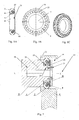
- a contact member 24 of the present invention comprises a holder or contact base 4, a row of cup-shaped conductive contact fingers 2 arranged around an outer periphery of the holder 4, and a spring 3 arranged between the holder 4 and each of the cup-shaped contact fingers 2.
- a plurality of contact finger slots 27 are formed in the holder 4, and one of the cup-shaped contact fingers 2 and the springs 3 are contained in each of the contact finger slot 27.
- the spring 3 is mounted in the contact slot 27 in an angle from radial direction, such that the contact fingers are provided with longitudinal and radial elastic/floating ability.
- the contact member 24 further comprises a press plate 1 integrally formed with the holder 4.
- the pressure plate 1 is configured to pre-press the spring 3.
- Figs. 1B and 1C illustrates the integrally formed circular press plate 1.
- the press plate 1 is connected with the holder at multiple positions through an integrated connecting rod (not shown).
- the contact finger 2 and the spring 3 are positioned in the contact finger slot under the press plate 1, so as to limit or restrain the contact figure 2 from moving in a direction away from the spring 3.
- any appropriate stopping mechanism such as a plurality of press plates fixedly connected to or integrally formed with the holder 4, each for the respective contact finger.
- the contact finger 2 comprises a first contact portion 15 on a side of the contact member 24, and a second contact portion 16 disposed on the outer periphery of the contact member 24.
- the contact member 24 (holder 4) is substantially in shape of a circular ring and comprises an aperture 17.
- a groove 18 for containing a sliding member is formed in the holder 4 on one side where no contact figure 2 is arranged.
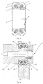
- a contact system 25 comprising the contact member 24 of Fig. 1 .
- the contact system 25 comprises a first conductor 5, a second conductor 8, and the contact member 24 mounted on the first conductor 5.
- the first conductor 5 is in shape of a rod extending substantially along an axis LL', and the second conductor 8 is provided with an opening 19 for containing the first conductor and the contact member.
- the opening 19 is generally arranged coaxially with the rod-shaped first conductor.
- the first conductor 5 is allowed to be radially offset with respect to the opening 19.
- the first conductor 5 comprises a conductive body 26, and a retainer 10 fastened to the body 26 through a screw 21.
- the retainer 10 is preferably non-conductive.
- the conductive body 26 comprises a major diameter portion 28 and at a tip end, a minor diameter portion 29.
- the minor diameter portion 29 has a diameter smaller than that of the aperture 17, such that the body 26 and the retainer 10 together define a radially outward containing groove 23.
- the holder 4 of the contact member 24 when installation, the holder 4 of the contact member 24 is positioned over the minor diameter portion 29 of the body 26 through the aperture 17, and subsequently the retainer 10 is fastened to the body 26 through the screw 21 and accordingly the containing groove 23 is formed, with a radial gap 20 between the holder 4 and the bottom of the containing groove 23, such that the contact member 24, in particular the holder 4, is radially displaceable with respect to the first conductor 5.
- the above-mentioned gap or the diameter difference between the major diameter portion 28 and the minor diameter portion 29 allows the radial displacement of the holder of the present invention with respect to the first conductor.
- the retainer and the body are separated In the illustrated embodiment, but they can be formed integrally, as long as the contact member 24 is contained in the containing groove with the radial gap.
- a side wall of the containing groove 23 in the first conductor 5 defines a radial contact surface or radial displacement working surface 6 which contacts and is electrically connected with the first contact portion 15, and the opening 19 of the second conductor 8 defines an axial contact surface or axial displacement working surface 7 which contacts with the second contact portion 16.
- the contact member 24 is allowed to be radially displaceable along the radial contact surface 6 with respect to the first conductor 5, with the electrical connection with the first conductor 5.
- the contact member 24 is allowed to be axially displaceable along the axial contact surface 7, with the electrical connection with the second conductor 8.
- the contact system further comprises a sliding ring 9 disposed between the holder and the holder 4.
- the sliding ring 9 is contained in the groove 18 of the holder.
- the sliding ring 9 is particularly applicable to decrease friction between the contact member 4 and the first conductor 5.
- the contact member 24 is configured as a movable contactor, and the second conductor 8 is fixed or provided with a fixed contactor (not shown) as known in the prior art such that the first conductor 5 and the contact member 24 is movable along the axial direction, such as along the axis LL', into the opening of the second conductor 8, such that the second contact portion 16 of the contact finger 2 is movable along the axial contact surface 7.
- the radial movement of the first conductor 5 causes the minor diameter portion 29 of the body to move in the aperture 17, without contacting with the holder.
- the axial position of the contact member 24 is retained by the first conductor 5.
- a noticeable axial movement of the contact member 24 with respect to the first conductor 5 is restricted by the containing groove 23 defined by the body 26 and the retainer 10.
- the first conductor 5 and the contact member 24 are axially moveable together with respect to the second conductor 8.
- the integral contact member 24 is shown.
- the contact member of the present invention for example, comprises multiple contact member parts (not shown) that collectively form a closed ring, the radial and axial positions of the ring being respectively retained by the first and second conductors, such that the contact member is still allowed to be radially or axially movable with respect to the first or second conductor, respectively.
- FIG. 3 another embodiment of the contact member 24 is illustrated.
- the components of the contact member 24 are similar to those shown in Fig. 1 , except that the contact finger mechanism of Fig. 3 comprises two rows of the cup-shaped contact fingers 2 arranged side by side, two respective rows of the springs 3, and two press plates 1.
- the contact member 24 is dispensed from the sliding ring 9 and the groove 18, as shown in Fig. 3 .
- the sliding member and the groove are arranged at other positions between the first conductor 5 and the contact member 24.
- a contact system 25 comprising the contact member 24 of Fig. 3 , which contact system 25 is configured similarly to the contact system of Fig. 2 , for example, the containing groove 23 for containing the contact member 24 is defined between the body 26 and the retainer 10 of the first conductor 5, and the radial gap 20 is formed between the bottom of the containing groove 23 and the holder 4, with a difference that the first contact portion 15 of one row of the contact fingers 2 of the contact member 24 in Fig. 4 is in contact and electric connection with the body 26 of the first conductor 5, while the first contact portion 15 of the other row of the contact fingers 2 is in contact and electric connection with a conductive retainer 11 of the first conductor 5. That is, the body 26 and the retainer 11 of the first conductor 5 each define a radial contact surface 6, 6' respectively. The second contact portion 16 of each contact finger 2 is still in contact and electric connection with the axial contact surface 7 of the second conductor 8.
- FIGs. 5A and 5B further another embodiment of the contact member 24 is illustrated. At least part of elasticity and floatability of the contact finger mechanism in the embodiments of Figs. 1-4 and 7 is provided by the springs, while the elasticity of the contact finger mechanism in Figs. 5A and 5B are completely provided by the contact blade or contact finger per se. Moreover, as compared to what is illustrated inFigs 1-4 and 6 that the contact finger 2 of the contact finger mechanism defines both the first contact portion 15 and the second contact portion 16 , the contact finger mechanism of the contact member 24 as shown in Figs. 5A and 5B comprises a first circular contact finger 13 defining the first contact portion 15, and a second circular contact finger 12 defining the second contact portion 16.
- the first contact finger 13 is arranged on a side of the contact member 24 and in contact with the radial contact surface 6 of the first conductor 5, and the second contact finger is arranged on an outer periphery of the contact member 24 and in contact with the axial contact surface 7 of the second conductor 8.
- the contact member 24 comprises a holder 14 which at least electrically connects the first contact finger 13 with the second contact finger 12.
- the holder 14 is made from electrically conductive materials.
- the first and second contact fingers 12 and 13 are mounted and retained on the holder 4, such that the stopping mechanism can be omitted from the contact member 24 of the embodiment.
- the illustrated first contact finger and second contact finger is in form of a ring-shaped integral contact finger respectively, but it is conceivable to provide a plurality of first and second contact fingers similar to the above-mentioned embodiments,.
- the contact member 24 may comprise a groove for containing the sliding ring 9.
- the contact member of the contact system as shown in Fig. 2 can be replaced with the contact member 24 of the embodiment as shown in Figs. 5A and 5B to form a new contact system.
- features of the contact fingers (contact blades) of the said embodiment and of the above-mentioned embodiments can be interchanged or combined with each other to yield a new embodiment of the contact member.
- the contact fingers in Figs. 1A-1C can be modified to have elasticity per se to provide elasticity for the contact finger mechanism, or the first and second contact fingers in Fig. 5 can be equipped with a spring.
- FIG. 6A and 6B yet another embodiment of the contact member is illustrated.
- the embodiment illustrated in Figs. 6A and 6B is similar to the embodiment of Figs. 5A and 5B , except that in replacement of the groove in the contact member of Figs. 5A and 5B , another juxtaposed circular first contact finger
- the contact finger mechanism of the contact member 24 comprises around the periphery of the holder, two first contact fingers arranged side by side and one second contact finger arranged between the two first contact fingers, with the two first contact fingers, for example, contacting with the radial contact surface 6, 6' of the body and of the retainers 10 and 11 in the first conductor 5 respectively, while the second contact finger contacting with the axial contact surface 7 of the second conductor 8.
- the contact member of the contact system as shown in Fig. 4 can be replaced with the contact member 24 of the embodiment as shown in Figs. 6A and 6B to yield a new contact system.
- FIG. 7 still another embodiment of the contact system 25 according to the present invention is illustrated.
- the second conductor 8 of the contact system in Fig. 7 is in shape of a rod substantially extending along the axial direction, and the first conductor 5 is provided with a respective opening or aperture 22.
- the first conductor 5 is provided with a body 26, a retainer 10, and a containing groove 23 defined by the body 26 and the retainer 10 for containing the contact member, with a radial gap 20 between the bottom of the containing groove 23 and the holder of the contact member, but the containing groove 23 is directed radially inward.
- the other components of the contact system of Fig. 7 reference can be made to the above-mentioned embodiments of contact member, with their combination and modification falling within the scope of the present invention.
- the contact fingers are mounted on the contact member.
- the contact finger can be accordingly arranged on the first conductor and/or the second conductor.
- the radial contact surface 106 of the body 26 and the radial contact surface 106' of the retainer 14 in the first conductor 5 are both provided with the first contact blades or fingers 113, 113' respectively. Accordingly, no contact finger is arranged in the first contact portion 115 of the contact member.
- the contact member is still provided with the second contact blade or contact finger 112 for defining the second contact portion of the contact member (not indicated).
- the axial contact surface of the second conductor 8 is provided with the contact finger for contacting with the second contact portion of the contact member.
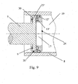
- a respective containing groove 23' is arranged in the contact member.
- the rod-shaped first conductor 5 and the second conductor for defining the opening 19 are provided.
- the containing groove 23' directed radially inward is formed in an aperture 17 of the contact member 24.
- the first conductor 5 is provided with a projection 30 thereon, which is contained in the containing groove 23' with a radial gap 20'.
- the first contact portion and the second contact portion of the contact member 24 are respectively defined by a first contact finger 13' and a second contact finger 12' arranged thereon.
- the first contact finger 13' is arranged on a side wall of the containing groove 23', i.e., within the inner periphery of the opening 17 of the contact member 24, and in contact with the radial contact surface (not indicated) defined in the projection 30 of the first conductor 5.
- the second contact finger 12' is arranged on the outer periphery of the contact member and in contact with the axial contact surface (not indicated) of the opening 19 of the second conductor 8.
- a combination between the aforesaid contact system and the containing groove of contact base may yield a new embodiment.
- the containing groove formed on the outer periphery of the contact base 24 is applicable to a configuration in which the second conductor is in a shape of rod and the first conductor defines the opening.
- the positions and arrangements of the contact fingers are applicable to be combined with the current embodiment to yield a new embodiment.
- the second conductor can be movable or a contactor is provided on the second conductor as a movable contactor, with the first conductor and the contact member of the present invention to be axially stationary, which also falls within the scope of the present invention.
Landscapes
- Contacts (AREA)
Applications Claiming Priority (1)
| Application Number | Priority Date | Filing Date | Title |
|---|---|---|---|
| CN201210370818.3A CN102903543B (zh) | 2012-09-28 | 2012-09-28 | 触头系统 |
Publications (3)
| Publication Number | Publication Date |
|---|---|
| EP2725596A2 true EP2725596A2 (fr) | 2014-04-30 |
| EP2725596A3 EP2725596A3 (fr) | 2015-03-04 |
| EP2725596B1 EP2725596B1 (fr) | 2019-07-24 |
Family
ID=47575737
Family Applications (1)
| Application Number | Title | Priority Date | Filing Date |
|---|---|---|---|
| EP13186411.8A Active EP2725596B1 (fr) | 2012-09-28 | 2013-09-27 | Système de contact |
Country Status (3)
| Country | Link |
|---|---|
| US (1) | US20140094041A1 (fr) |
| EP (1) | EP2725596B1 (fr) |
| CN (1) | CN102903543B (fr) |
Cited By (2)
| Publication number | Priority date | Publication date | Assignee | Title |
|---|---|---|---|---|
| WO2015071731A1 (fr) * | 2013-11-15 | 2015-05-21 | Eaton Corporation | Pôle scellé massif |
| CN105244196A (zh) * | 2015-09-29 | 2016-01-13 | 厦门华泰利机电有限公司 | 一种触臂结构 |
Families Citing this family (17)
| Publication number | Priority date | Publication date | Assignee | Title |
|---|---|---|---|---|
| CN104167624A (zh) * | 2013-05-20 | 2014-11-26 | 镇江华浩通信器材有限公司 | 保护设备接口的射频同轴连接器 |
| CN104332331B (zh) * | 2014-11-06 | 2017-01-11 | 佳一电气有限公司 | 一种触头系统 |
| CN104377047B (zh) * | 2014-12-01 | 2017-01-18 | 哈尔滨理工大学 | 可自动调节接触面角度的电气动触头及结构 |
| CN104916991A (zh) * | 2015-05-29 | 2015-09-16 | 桐乡市筱雅电子商务有限公司 | 一种带滑槽的供电设备的供电接口装置 |
| CN104868307A (zh) * | 2015-05-29 | 2015-08-26 | 郑旭 | 一种设置有含漏斗形区域导向孔的供电设备的供电接口装置 |
| CN104934791A (zh) * | 2015-05-29 | 2015-09-23 | 吴刚 | 一种使用锥齿轮传动的供电设备接口装置 |
| CN104868309A (zh) * | 2015-05-29 | 2015-08-26 | 永嘉路路通进出口有限公司 | 一种使用接触传感器的供电设备的供电接口装置 |
| CN104953373A (zh) * | 2015-05-29 | 2015-09-30 | 杭州涛度电子商务商行 | 一种快速散热的供电设备的供电接口装置 |
| CN104916988A (zh) * | 2015-05-29 | 2015-09-16 | 尚庆光 | 一种带弹片的供电设备的供电接口装置 |
| CN104868305A (zh) * | 2015-05-29 | 2015-08-26 | 郑旭 | 一种带滚轮槽的供电设备的供电接口装置 |
| CN104953374A (zh) * | 2015-05-29 | 2015-09-30 | 泉州市洛江区大明鞋厂 | 一种使用定位凸出定位并可锁定的供电设备接口装置 |
| CN104868310A (zh) * | 2015-05-29 | 2015-08-26 | 海盐县通元弗斯特工艺品厂 | 一种单电机驱动的供电设备的供电接口装置 |
| CN104916989A (zh) * | 2015-05-29 | 2015-09-16 | 陈文文 | 一种带滚轮的供电设备的供电接口装置 |
| CN104916986A (zh) * | 2015-05-29 | 2015-09-16 | 吴刚 | 一种使用螺杆驱动电气连接的供电设备接口装置 |
| CN104868308A (zh) * | 2015-05-29 | 2015-08-26 | 陈文文 | 一种通过风扇散热的供电设备的供电接口装置 |
| CN113839242A (zh) * | 2021-09-29 | 2021-12-24 | 天津尚圣科技有限公司 | 一种高压电气设备用触指及其微粒捕捉结构 |
| CN114649161B (zh) * | 2021-12-16 | 2024-04-05 | 河南平高电气股份有限公司 | 一种三工位隔离接地开关及隔离静触头 |
Family Cites Families (12)
| Publication number | Priority date | Publication date | Assignee | Title |
|---|---|---|---|---|
| SE159423C1 (fr) * | ||||
| DE972235C (de) * | 1943-09-09 | 1959-06-11 | Aeg | Ringkontakt fuer hohe Stroeme |
| US2426387A (en) * | 1944-04-04 | 1947-08-26 | Ite Circuit Breaker Ltd | Circuit breaker contact |
| DE1002845B (de) * | 1953-06-01 | 1957-02-21 | Voigt & Haeffner Ag | Kontaktanordnung fuer bewegliche Schaltstifte |
| US3070770A (en) * | 1959-12-21 | 1962-12-25 | Mc Graw Edison Co | Electrical contacts |
| US3713075A (en) * | 1971-04-26 | 1973-01-23 | Ite Imperial Corp | Dielectric shield for plug-in contacts |
| US4111511A (en) * | 1977-09-23 | 1978-09-05 | Westinghouse Electric Corp. | High current contact assembly |
| US4514025A (en) * | 1982-11-08 | 1985-04-30 | Square D Company | Low resistance electrical connector |
| JPH01114314A (ja) * | 1987-10-26 | 1989-05-08 | Mitsubishi Electric Corp | ガス絶縁開閉装置 |
| GB2315167B (en) * | 1996-07-08 | 1999-04-21 | Amphenol Corp | Electrical connector and cable termination system |
| JP2011507162A (ja) * | 2007-12-06 | 2011-03-03 | バル・シール・エンジニアリング | インラインコネクタ |
| JP4212645B1 (ja) * | 2008-04-14 | 2009-01-21 | 三菱電機株式会社 | 接触子 |
-
2012
- 2012-09-28 CN CN201210370818.3A patent/CN102903543B/zh active Active
-
2013
- 2013-09-27 EP EP13186411.8A patent/EP2725596B1/fr active Active
- 2013-09-27 US US14/039,522 patent/US20140094041A1/en not_active Abandoned
Cited By (3)
| Publication number | Priority date | Publication date | Assignee | Title |
|---|---|---|---|---|
| WO2015071731A1 (fr) * | 2013-11-15 | 2015-05-21 | Eaton Corporation | Pôle scellé massif |
| CN105244196A (zh) * | 2015-09-29 | 2016-01-13 | 厦门华泰利机电有限公司 | 一种触臂结构 |
| CN105244196B (zh) * | 2015-09-29 | 2018-06-26 | 厦门华泰利机电有限公司 | 一种触臂结构 |
Also Published As
| Publication number | Publication date |
|---|---|
| US20140094041A1 (en) | 2014-04-03 |
| CN102903543B (zh) | 2015-01-21 |
| CN102903543A (zh) | 2013-01-30 |
| EP2725596B1 (fr) | 2019-07-24 |
| EP2725596A3 (fr) | 2015-03-04 |
Similar Documents
| Publication | Publication Date | Title |
|---|---|---|
| EP2725596B1 (fr) | Système de contact | |
| US20070246444A1 (en) | Contact system for an electrical switching device | |
| US9711299B2 (en) | Contact-finger-element and tulip-contact-assembly for switching device | |
| US9601856B2 (en) | Connecting device for a switchgear apparatus | |
| US20130146433A1 (en) | Electrical contact arrangement and air insulated medium voltage circuit breaker including the electrical contact arrangement | |
| US7884298B2 (en) | Switch for a switchgear assembly for power supply and distribution | |
| US9570246B2 (en) | Disconnector for switchgear | |
| US9412548B2 (en) | Circuit breakers with handle bearing sleeves | |
| CN105321739A (zh) | 电力用开闭器 | |
| US20140185193A1 (en) | Switchgear spout design | |
| US10256059B2 (en) | Magnetic switch | |
| EP3772080A2 (fr) | Commutateurs comportant des composants de protection contre les surintensités intégrés | |
| SU1080764A3 (ru) | Контактна система | |
| CN107533930A (zh) | 具有灭弧装置的开关设备 | |
| EP3772742B1 (fr) | Pôle de commutation basse tension | |
| CA2833486C (fr) | Appareil de commutation electrique a tension moyenne ou elevee | |
| CN110911208B (zh) | 高压直流隔离开关 | |
| EP3240001A1 (fr) | Dispositif à élément de contact de forme cylindrique pour un commutateur à trois positions dans des dispositifs de commutation à moyenne ou haute tension à isolation gazeuse | |
| ES2941310T3 (es) | Sistema de contacto auxiliar accionado por resorte para conmutación de transferencia de bus en un interruptor de corte central | |
| ES3036775T3 (en) | Electrical switching apparatus for guiding high persistent currents and very high short-circuit currents | |
| EP3629350B1 (fr) | Commutateur à moyenne ou haute tension ayant une connexion mécanique de type palier sphérique | |
| WO2015036885A1 (fr) | Ensemble doigts de contact d'un disjoncteur | |
| KR20160059063A (ko) | 진공차단기의 튤립형 접점 | |
| KR101605138B1 (ko) | 단로기 | |
| WO2013010559A1 (fr) | Commutateur auxiliaire combinant des éléments rotatifs et linéaires |
Legal Events
| Date | Code | Title | Description |
|---|---|---|---|
| PUAI | Public reference made under article 153(3) epc to a published international application that has entered the european phase |
Free format text: ORIGINAL CODE: 0009012 |
|
| 17P | Request for examination filed |
Effective date: 20130927 |
|
| AK | Designated contracting states |
Kind code of ref document: A2 Designated state(s): AL AT BE BG CH CY CZ DE DK EE ES FI FR GB GR HR HU IE IS IT LI LT LU LV MC MK MT NL NO PL PT RO RS SE SI SK SM TR |
|
| AX | Request for extension of the european patent |
Extension state: BA ME |
|
| PUAL | Search report despatched |
Free format text: ORIGINAL CODE: 0009013 |
|
| AK | Designated contracting states |
Kind code of ref document: A3 Designated state(s): AL AT BE BG CH CY CZ DE DK EE ES FI FR GB GR HR HU IE IS IT LI LT LU LV MC MK MT NL NO PL PT RO RS SE SI SK SM TR |
|
| AX | Request for extension of the european patent |
Extension state: BA ME |
|
| RIC1 | Information provided on ipc code assigned before grant |
Ipc: H01H 1/50 20060101ALI20150128BHEP Ipc: H01R 13/17 20060101ALI20150128BHEP Ipc: H01H 1/38 20060101AFI20150128BHEP Ipc: H01R 13/187 20060101ALI20150128BHEP |
|
| 17P | Request for examination filed |
Effective date: 20150824 |
|
| RBV | Designated contracting states (corrected) |
Designated state(s): AL AT BE BG CH CY CZ DE DK EE ES FI FR GB GR HR HU IE IS IT LI LT LU LV MC MK MT NL NO PL PT RO RS SE SI SK SM TR |
|
| GRAP | Despatch of communication of intention to grant a patent |
Free format text: ORIGINAL CODE: EPIDOSNIGR1 |
|
| STAA | Information on the status of an ep patent application or granted ep patent |
Free format text: STATUS: GRANT OF PATENT IS INTENDED |
|
| INTG | Intention to grant announced |
Effective date: 20190207 |
|
| GRAS | Grant fee paid |
Free format text: ORIGINAL CODE: EPIDOSNIGR3 |
|
| GRAA | (expected) grant |
Free format text: ORIGINAL CODE: 0009210 |
|
| STAA | Information on the status of an ep patent application or granted ep patent |
Free format text: STATUS: THE PATENT HAS BEEN GRANTED |
|
| AK | Designated contracting states |
Kind code of ref document: B1 Designated state(s): AL AT BE BG CH CY CZ DE DK EE ES FI FR GB GR HR HU IE IS IT LI LT LU LV MC MK MT NL NO PL PT RO RS SE SI SK SM TR |
|
| REG | Reference to a national code |
Ref country code: GB Ref legal event code: FG4D |
|
| REG | Reference to a national code |
Ref country code: CH Ref legal event code: EP |
|
| REG | Reference to a national code |
Ref country code: DE Ref legal event code: R096 Ref document number: 602013058113 Country of ref document: DE |
|
| REG | Reference to a national code |
Ref country code: AT Ref legal event code: REF Ref document number: 1159192 Country of ref document: AT Kind code of ref document: T Effective date: 20190815 |
|
| REG | Reference to a national code |
Ref country code: IE Ref legal event code: FG4D |
|
| REG | Reference to a national code |
Ref country code: NL Ref legal event code: FP |
|
| REG | Reference to a national code |
Ref country code: LT Ref legal event code: MG4D |
|
| REG | Reference to a national code |
Ref country code: AT Ref legal event code: MK05 Ref document number: 1159192 Country of ref document: AT Kind code of ref document: T Effective date: 20190724 |
|
| PG25 | Lapsed in a contracting state [announced via postgrant information from national office to epo] |
Ref country code: AT Free format text: LAPSE BECAUSE OF FAILURE TO SUBMIT A TRANSLATION OF THE DESCRIPTION OR TO PAY THE FEE WITHIN THE PRESCRIBED TIME-LIMIT Effective date: 20190724 Ref country code: NO Free format text: LAPSE BECAUSE OF FAILURE TO SUBMIT A TRANSLATION OF THE DESCRIPTION OR TO PAY THE FEE WITHIN THE PRESCRIBED TIME-LIMIT Effective date: 20191024 Ref country code: SE Free format text: LAPSE BECAUSE OF FAILURE TO SUBMIT A TRANSLATION OF THE DESCRIPTION OR TO PAY THE FEE WITHIN THE PRESCRIBED TIME-LIMIT Effective date: 20190724 Ref country code: BG Free format text: LAPSE BECAUSE OF FAILURE TO SUBMIT A TRANSLATION OF THE DESCRIPTION OR TO PAY THE FEE WITHIN THE PRESCRIBED TIME-LIMIT Effective date: 20191024 Ref country code: HR Free format text: LAPSE BECAUSE OF FAILURE TO SUBMIT A TRANSLATION OF THE DESCRIPTION OR TO PAY THE FEE WITHIN THE PRESCRIBED TIME-LIMIT Effective date: 20190724 Ref country code: LT Free format text: LAPSE BECAUSE OF FAILURE TO SUBMIT A TRANSLATION OF THE DESCRIPTION OR TO PAY THE FEE WITHIN THE PRESCRIBED TIME-LIMIT Effective date: 20190724 Ref country code: PT Free format text: LAPSE BECAUSE OF FAILURE TO SUBMIT A TRANSLATION OF THE DESCRIPTION OR TO PAY THE FEE WITHIN THE PRESCRIBED TIME-LIMIT Effective date: 20191125 Ref country code: FI Free format text: LAPSE BECAUSE OF FAILURE TO SUBMIT A TRANSLATION OF THE DESCRIPTION OR TO PAY THE FEE WITHIN THE PRESCRIBED TIME-LIMIT Effective date: 20190724 |
|
| PG25 | Lapsed in a contracting state [announced via postgrant information from national office to epo] |
Ref country code: RS Free format text: LAPSE BECAUSE OF FAILURE TO SUBMIT A TRANSLATION OF THE DESCRIPTION OR TO PAY THE FEE WITHIN THE PRESCRIBED TIME-LIMIT Effective date: 20190724 Ref country code: GR Free format text: LAPSE BECAUSE OF FAILURE TO SUBMIT A TRANSLATION OF THE DESCRIPTION OR TO PAY THE FEE WITHIN THE PRESCRIBED TIME-LIMIT Effective date: 20191025 Ref country code: LV Free format text: LAPSE BECAUSE OF FAILURE TO SUBMIT A TRANSLATION OF THE DESCRIPTION OR TO PAY THE FEE WITHIN THE PRESCRIBED TIME-LIMIT Effective date: 20190724 Ref country code: IS Free format text: LAPSE BECAUSE OF FAILURE TO SUBMIT A TRANSLATION OF THE DESCRIPTION OR TO PAY THE FEE WITHIN THE PRESCRIBED TIME-LIMIT Effective date: 20191124 Ref country code: AL Free format text: LAPSE BECAUSE OF FAILURE TO SUBMIT A TRANSLATION OF THE DESCRIPTION OR TO PAY THE FEE WITHIN THE PRESCRIBED TIME-LIMIT Effective date: 20190724 Ref country code: ES Free format text: LAPSE BECAUSE OF FAILURE TO SUBMIT A TRANSLATION OF THE DESCRIPTION OR TO PAY THE FEE WITHIN THE PRESCRIBED TIME-LIMIT Effective date: 20190724 |
|
| PG25 | Lapsed in a contracting state [announced via postgrant information from national office to epo] |
Ref country code: TR Free format text: LAPSE BECAUSE OF FAILURE TO SUBMIT A TRANSLATION OF THE DESCRIPTION OR TO PAY THE FEE WITHIN THE PRESCRIBED TIME-LIMIT Effective date: 20190724 |
|
| PG25 | Lapsed in a contracting state [announced via postgrant information from national office to epo] |
Ref country code: RO Free format text: LAPSE BECAUSE OF FAILURE TO SUBMIT A TRANSLATION OF THE DESCRIPTION OR TO PAY THE FEE WITHIN THE PRESCRIBED TIME-LIMIT Effective date: 20190724 Ref country code: DK Free format text: LAPSE BECAUSE OF FAILURE TO SUBMIT A TRANSLATION OF THE DESCRIPTION OR TO PAY THE FEE WITHIN THE PRESCRIBED TIME-LIMIT Effective date: 20190724 Ref country code: PL Free format text: LAPSE BECAUSE OF FAILURE TO SUBMIT A TRANSLATION OF THE DESCRIPTION OR TO PAY THE FEE WITHIN THE PRESCRIBED TIME-LIMIT Effective date: 20190724 Ref country code: EE Free format text: LAPSE BECAUSE OF FAILURE TO SUBMIT A TRANSLATION OF THE DESCRIPTION OR TO PAY THE FEE WITHIN THE PRESCRIBED TIME-LIMIT Effective date: 20190724 |
|
| PG25 | Lapsed in a contracting state [announced via postgrant information from national office to epo] |
Ref country code: CZ Free format text: LAPSE BECAUSE OF FAILURE TO SUBMIT A TRANSLATION OF THE DESCRIPTION OR TO PAY THE FEE WITHIN THE PRESCRIBED TIME-LIMIT Effective date: 20190724 Ref country code: MC Free format text: LAPSE BECAUSE OF FAILURE TO SUBMIT A TRANSLATION OF THE DESCRIPTION OR TO PAY THE FEE WITHIN THE PRESCRIBED TIME-LIMIT Effective date: 20190724 Ref country code: IS Free format text: LAPSE BECAUSE OF FAILURE TO SUBMIT A TRANSLATION OF THE DESCRIPTION OR TO PAY THE FEE WITHIN THE PRESCRIBED TIME-LIMIT Effective date: 20200224 Ref country code: SM Free format text: LAPSE BECAUSE OF FAILURE TO SUBMIT A TRANSLATION OF THE DESCRIPTION OR TO PAY THE FEE WITHIN THE PRESCRIBED TIME-LIMIT Effective date: 20190724 Ref country code: SK Free format text: LAPSE BECAUSE OF FAILURE TO SUBMIT A TRANSLATION OF THE DESCRIPTION OR TO PAY THE FEE WITHIN THE PRESCRIBED TIME-LIMIT Effective date: 20190724 |
|
| REG | Reference to a national code |
Ref country code: CH Ref legal event code: PL |
|
| REG | Reference to a national code |
Ref country code: DE Ref legal event code: R097 Ref document number: 602013058113 Country of ref document: DE |
|
| PLBE | No opposition filed within time limit |
Free format text: ORIGINAL CODE: 0009261 |
|
| STAA | Information on the status of an ep patent application or granted ep patent |
Free format text: STATUS: NO OPPOSITION FILED WITHIN TIME LIMIT |
|
| PG2D | Information on lapse in contracting state deleted |
Ref country code: IS |
|
| PG25 | Lapsed in a contracting state [announced via postgrant information from national office to epo] |
Ref country code: CH Free format text: LAPSE BECAUSE OF NON-PAYMENT OF DUE FEES Effective date: 20190930 Ref country code: LI Free format text: LAPSE BECAUSE OF NON-PAYMENT OF DUE FEES Effective date: 20190930 Ref country code: IE Free format text: LAPSE BECAUSE OF NON-PAYMENT OF DUE FEES Effective date: 20190927 Ref country code: LU Free format text: LAPSE BECAUSE OF NON-PAYMENT OF DUE FEES Effective date: 20190927 |
|
| 26N | No opposition filed |
Effective date: 20200603 |
|
| REG | Reference to a national code |
Ref country code: BE Ref legal event code: MM Effective date: 20190930 |
|
| PG25 | Lapsed in a contracting state [announced via postgrant information from national office to epo] |
Ref country code: SI Free format text: LAPSE BECAUSE OF FAILURE TO SUBMIT A TRANSLATION OF THE DESCRIPTION OR TO PAY THE FEE WITHIN THE PRESCRIBED TIME-LIMIT Effective date: 20190724 Ref country code: BE Free format text: LAPSE BECAUSE OF NON-PAYMENT OF DUE FEES Effective date: 20190930 |
|
| PG25 | Lapsed in a contracting state [announced via postgrant information from national office to epo] |
Ref country code: CY Free format text: LAPSE BECAUSE OF FAILURE TO SUBMIT A TRANSLATION OF THE DESCRIPTION OR TO PAY THE FEE WITHIN THE PRESCRIBED TIME-LIMIT Effective date: 20190724 |
|
| PG25 | Lapsed in a contracting state [announced via postgrant information from national office to epo] |
Ref country code: HU Free format text: LAPSE BECAUSE OF FAILURE TO SUBMIT A TRANSLATION OF THE DESCRIPTION OR TO PAY THE FEE WITHIN THE PRESCRIBED TIME-LIMIT; INVALID AB INITIO Effective date: 20130927 Ref country code: MT Free format text: LAPSE BECAUSE OF FAILURE TO SUBMIT A TRANSLATION OF THE DESCRIPTION OR TO PAY THE FEE WITHIN THE PRESCRIBED TIME-LIMIT Effective date: 20190724 |
|
| PG25 | Lapsed in a contracting state [announced via postgrant information from national office to epo] |
Ref country code: MK Free format text: LAPSE BECAUSE OF FAILURE TO SUBMIT A TRANSLATION OF THE DESCRIPTION OR TO PAY THE FEE WITHIN THE PRESCRIBED TIME-LIMIT Effective date: 20190724 |
|
| P01 | Opt-out of the competence of the unified patent court (upc) registered |
Effective date: 20230521 |
|
| PGFP | Annual fee paid to national office [announced via postgrant information from national office to epo] |
Ref country code: NL Payment date: 20240820 Year of fee payment: 12 |
|
| PGFP | Annual fee paid to national office [announced via postgrant information from national office to epo] |
Ref country code: DE Payment date: 20240820 Year of fee payment: 12 |
|
| PGFP | Annual fee paid to national office [announced via postgrant information from national office to epo] |
Ref country code: GB Payment date: 20240822 Year of fee payment: 12 |
|
| PGFP | Annual fee paid to national office [announced via postgrant information from national office to epo] |
Ref country code: FR Payment date: 20240820 Year of fee payment: 12 |
|
| PGFP | Annual fee paid to national office [announced via postgrant information from national office to epo] |
Ref country code: IT Payment date: 20240820 Year of fee payment: 12 |