EP2725670A1 - Kanalabschnitt zur Herstellung eines Kanals, Kanal und Verfahren zur Bereitstellung und Herstellung eines derartigen Kanals - Google Patents
Kanalabschnitt zur Herstellung eines Kanals, Kanal und Verfahren zur Bereitstellung und Herstellung eines derartigen Kanals Download PDFInfo
- Publication number
- EP2725670A1 EP2725670A1 EP12190164.9A EP12190164A EP2725670A1 EP 2725670 A1 EP2725670 A1 EP 2725670A1 EP 12190164 A EP12190164 A EP 12190164A EP 2725670 A1 EP2725670 A1 EP 2725670A1
- Authority
- EP
- European Patent Office
- Prior art keywords
- channel
- channel portion
- portions
- connection means
- end opening
- Prior art date
- Legal status (The legal status is an assumption and is not a legal conclusion. Google has not performed a legal analysis and makes no representation as to the accuracy of the status listed.)
- Granted
Links
Images


Classifications
-
- H—ELECTRICITY
- H02—GENERATION; CONVERSION OR DISTRIBUTION OF ELECTRIC POWER
- H02G—INSTALLATION OF ELECTRIC CABLES OR LINES, OR OF COMBINED OPTICAL AND ELECTRIC CABLES OR LINES
- H02G3/00—Installations of electric cables or lines or protective tubing therefor in or on buildings, equivalent structures or vehicles
- H02G3/02—Details
- H02G3/04—Protective tubing or conduits, e.g. cable ladders or cable troughs
- H02G3/0406—Details thereof
- H02G3/0418—Covers or lids; Their fastenings
-
- H—ELECTRICITY
- H02—GENERATION; CONVERSION OR DISTRIBUTION OF ELECTRIC POWER
- H02G—INSTALLATION OF ELECTRIC CABLES OR LINES, OR OF COMBINED OPTICAL AND ELECTRIC CABLES OR LINES
- H02G3/00—Installations of electric cables or lines or protective tubing therefor in or on buildings, equivalent structures or vehicles
- H02G3/02—Details
- H02G3/04—Protective tubing or conduits, e.g. cable ladders or cable troughs
- H02G3/0462—Tubings, i.e. having a closed section
- H02G3/0468—Corrugated
-
- H—ELECTRICITY
- H02—GENERATION; CONVERSION OR DISTRIBUTION OF ELECTRIC POWER
- H02G—INSTALLATION OF ELECTRIC CABLES OR LINES, OR OF COMBINED OPTICAL AND ELECTRIC CABLES OR LINES
- H02G3/00—Installations of electric cables or lines or protective tubing therefor in or on buildings, equivalent structures or vehicles
- H02G3/02—Details
- H02G3/06—Joints for connecting lengths of protective tubing or channels, to each other or to casings, e.g. to distribution boxes; Ensuring electrical continuity in the joint
- H02G3/0608—Joints for connecting non cylindrical conduits, e.g. channels
Definitions
- the present invention relates to a channel for use in underground cable or pipe installations, and a method for installing cables underground in such a channel.
- cables have been installed in overhead installations as it is a cost-efficient way of installing cables.
- overhead installations have several drawbacks such as being unaesthetic, constituting obstacles in developed areas, and in being exposed for vegetation, bad weather etc. Therefore, many state of the art cable installations are underground installations.
- Some underground cable installations are enabled by culverts, and other underground installations are enabled by cable pipes constituting a mechanical protection for the cables.
- the invention relates to an improvement of a cable pipe, normally buried in a particulate material such as sand, gravel, dirt or clay and the alike.
- a cable pipe normally buried in a particulate material such as sand, gravel, dirt or clay and the alike.
- Such cable pipes are normally first installed underground and subsequently cables are pulled through the installed pipes.
- a common problem with those cable pipes is that when pulling cables through the already installed pipes a high friction between the cable and the pipe is generated, especially if the cable is heavy and rigid and if the pipes are curved.
- State of the art solutions to this problem is primarily to use a pulling line or machine, which requires large forces, or to bury cable channels with preinstalled cables, which is heavy, expensive and inflexible. Therefore, a drawback with state of the art cable pipes solutions is that the installation is time consuming and costly.
- a general object of the invention is to provide an improved method for underground cable installations.
- a specific object of the invention is to provide a method and a cable channel that enables reduced time for installing a cable in an underground installation.
- the inventor has realized that by providing a cable channel portion with a design that enables the installer to arrange the cable in the channel before the cable channel is sealed, i.e. while the channel is open along a substantial part of its length, the installation is vastly facilitated. Further, by designing the cable channel portion with integrated end connecting means for enabling a positive interconnection between the channel portion and an adjacent channel portion the installation is further facilitated.
- a channel portion for forming a buried cable channel for buried cable or pipe installations
- said channel portion comprises: an elongate base portion, extending along a longitudinal direction between first and second end opening portions, first and second side wall portions, extending substantially perpendicular from longitudinal side portions of the base portion, wherein the base portion and the side wall portions are integrated to provide a substantially U-shaped cross section of the channel portion, as seen in a plane perpendicular to the longitudinal direction, wherein the first end opening portion is interconnectable with a second end opening portion of a second, identical, channel portion, and that the first and second end opening portions are provided with first and second end connecting means, respectively, for providing a positive interconnection between the first end opening portion and the second end opening portion of the second, identical channel portion.
- a "positive interlocking" means a form based connection. I.e. not an interlocking based merely on e.g. friction, but based on the form of the connecting means.
- the term “integrated” should be understood as permanently joined or preferably “formed in one piece”.
- longitudinal direction should be understood as the direction in which the cable channel substantially extends, which is the same direction as the cable to be installed will extend.
- the end connecting means are formed to interconnect two or more channel portions in a longitudinal direction in a short-end to short-end manner.
- an improved cable channel enabling facilitated underground cable installations. More specifically, allowing for an installer to arrange the cable in the channel before the cable channel is sealed, i.e. while the channel is open along a substantial part of its length, the installation is vastly facilitated. Further, by designing the cable channel portion with end connecting means so that it may be coupled to another cable channel portion to form a cable channel the installation is further facilitated.
- the cable channel portions is substantially U-shaped, when it is mated with another U-shaped channel portion so the portions together form a substantially closed channel with a substantially rectangular cross-section, when seen in a plane perpendicular to the longitudinal direction, less filling material is required to bury the channel than in conventional pipes with a corresponding circular cross-section.
- a U-shaped channel portion according to above has the advantage of not rolling away when being handled during production, transportation and installation.
- the U-shaped form allows for more effective transportations, requiring only approximately half the volume due to that one channel portion may be arranged partly inside another channel portion if the open sides of the U-shaped portions are arranged towards each other and slightly transversally displaced. Further, as the U-shaped channel portions do not roll, any fittings usually holding pipes with a circular cross-section in place may be eliminated.
- first end connection means present a radially inwardly extending flange and the second end connection means present a radially outwardly extending flange, and wherein the inwardly extending flange is sized and adapted to retain the outwardly extending flange in a longitudinal direction, when the second end opening portion is received in the first end opening portion.
- the first end opening portion itself forms the first end connection means and the second end opening portion itself forms said second type coupling means.
- a first channel portion may be longitudinally coupled to a second channel portion without the need of any external coupling means.
- the first end connection means of a first channel portion may be inserted into the second end connection means of a second channel portion, and thereby longitudinally couple the two channel portions.
- At least the side walls have a corrugated surface structure, wherein ridges and valleys forming the corrugated surface structure extend substantially perpendicular to the longitudinal direction.
- both the side walls and the base have a corrugated surface structure, wherein the ridges and valleys forming the corrugated surface structure extend substantially perpendicular to the longitudinal direction.
- corrugated is understood to include surface structures having periodically recurring valleys and ridges.
- the structure may be generally sinusoid, square, saw toothed, etc. Thereby, the channel portion's rigidity may be increased.
- a corrugation period is 10-120 mm, preferably 40-80 mm.
- the corrugation amplitude is 1-30 mm, preferably 5 - 15 mm.
- an outermost valley of the first end opening portion presents an inner space which is radially enlarged as compared to at least one further valley of the channel portion.
- the outermost valley of the first end opening portion enables a second end opening portion to be fitted inside the outermost valley. Consequently, the coupling for providing a positive interconnection between the first end opening portion and the second end opening portion of the second, identical channel portion may be enabled through the corrugated surface structure, and more specifically through the outermost valley and the radially outwardly extending flange.
- first and second end connection means are adapted for allowing a limited movement between a pair of interconnected channel portions.
- the movement may be a longitudinal displacement and/or an angular tilting.
- the outwardly extending flange when received in the valley, is displaceable and/or tiltable relative to the valley.
- the flexibility of a cable channel comprising a number of cable channel portions may be increased.
- the longitudinal displacement the length of the cable channel may be altered.
- the angle between a first channel portion and a second channel portion may be altered.
- An angular tilting means that a first channel portion's general extension forms an angle relative the general extension of a second portion.
- the angle may be between about 0 degrees and about ⁇ 25 degrees in any direction.
- the angle may be about ⁇ 15 degrees in any direction.
- the angle may be about ⁇ 10 degrees in any direction.
- outwardly extending flange when received in the valley, is displaceable and/or tiltable relative to the valley and displacement or tilting is limited by longitudinally spaced apart proximal and distal valley side walls.
- the displacement and tilting function may be achieved by means of the integrated corrugated structure constituting a rigid and simple construction providing a fail-safe function and low production costs.
- free edge portions of the first and second side walls present first and second long-side connection means, respectively, adapted for form-based engagement with corresponding long-side connection means of a second, similar channel portion, when the channel portion and the second channel portion are positioned so that their respective U-shaped cross-sections together form a substantially closed channel.
- the "long-side connecting means” are formed to interconnect two channel portions longitudinally aligned and transversally displaced in a long-side to long-side manner, so as to form a substantially closed channel. That is, the two channel portions forms a bottom channel portion and a top channel portion, respectively, interconnected to form a substantially closed channel.
- the second similar channel portion is not only similar, but identical, to the channel portion.
- only one type of channel portion may be used when installing a long cable channel comprising several channel portions.
- production costs may be kept low and installation facilitated.
- the first long-side connection means comprises a resilient locking element which is adapted to engage a locking shoulder forming part of the second long-side connection means.
- the long-side connection means may engage the second long-side connection means without an activation of the interconnection from an installer. Instead, the installer merely needs to bring the two connection means in abutment to each other, and then the connection means will engage by means of the resilience of the locking member of the first long-side connection means.
- a channel portion with a resilient locking member as described above will further facilitate installation of a cable channel.
- the locking element comprises a guide surface adapted for guiding the locking element into said engagement with the locking shoulder.
- first channel portion constituting a bottom channel guide
- second channel portion constituting a top channel guide
- the first connection means comprises a tongue protruding from its associated side wall edge portion and carrying the locking element.
- the locking element is easier to see and distinguish from the side wall edge portion and thus facilitating the installation process.
- the second connection means comprises a spacer arranged for spacing the locking shoulder from its associated side wall edge portion.
- the locking shoulder is easier to see and distinguish from the side wall edge portion and thus facilitating the installation process.
- the channel portion's wall thickness is about 3-10 mm, preferably about 4-8 mm and most preferably about 5-7mm. Thereby, the channel portion becomes very rigid and may cope with tough handling and large external forces without being deformed or braking.
- the channel portion's wall thickness is about 1-5 mm, preferably about 2-4 mm and most preferably about 3 mm. Thereby, each channel portion's weight may be fairly light and handling the channel portion in production, transportation and installation may thereby be facilitated.
- the entire channel portion is formed in one piece. Thereby, the manufacturing of the channel portion may be conducted through for example injection-molding. Further, no assembly of the channel portion is needed if it is produced in one piece.
- the channel portion is substantially solidly enclosed so that no particulate material may enter the channel.
- a channel comprising a first bottom channel portion as described in anyone of embodiments above and a second bottom channel portion as described in anyone of the embodiments above, said first and second channel portions being interconnected in an end-to-end relationship.
- the channel further comprises a first top channel portion as described in anyone of embodiments above, which is connected to one of the first and second bottom channel portions so as to form a closed channel.
- first top channel portion together with the interconnected one of the first and second bottom channel portion forms a closed channel with a substantially rectangular cross-section, when seen in a plane perpendicular to the longitudinal direction.
- the rectangular cross-section may have a radius so that it becomes a super rectangle.
- the objects are achieved by providing a buried cable or pipe installation comprising a channel with channel portions as described in any of the embodiments above.
- a method for providing a channel for a buried cable or pipe installation comprising: arranging a first channel portion as described in anyone of embodiments above such that its longitudinal opening faces substantially upwardly, arranging a second channel portion as described in anyone of embodiments above such that its longitudinal opening faces substantially upwardly and such that a first end opening portion of the first channel portion is interconnected with a second end opening portion of the second channel portion, introducing a cable or pipe in the longitudinal opening of the first and second channel portions, arranging a third channel portion , with its longitudinal opening facing substantially downwardly and longitudinally and laterally aligned with one of the first and second channel portions, interconnecting the third channel portion, along the longitudinal direction, with said one of the first and second channel portions, arranging a fourth channel portion, with its longitudinal opening facing substantially downwardly and longitudinally and laterally aligned with the other one of the first and second channel portions, and interconnecting the fourth channel portion, along the longitudinal direction, with said other
- the installation is facilitated due to that only the bottom portion of the channel is provided first and subsequently the cables may be arranged inside the first bottom half. Only thereafter may the top portion of the channel be provided to enclose the cables in the channel.
- This method eliminates the step of pulling or dragging the cables or pipes inside the channel, which is both time-consuming and resource heavy.
- the third and forth channel portions are also channel portions as described in anyone of embodiments above.
- the installation is further facilitated, as the installer does not need to identify what channel portion that is a top or bottom channel portion, but may use one channel portion in any place.
- the method further comprises the step of burying the channel in a particulate material, such as sand, gravel, macadam, clay, soil or the like.
- a particulate material such as sand, gravel, macadam, clay, soil or the like.
- an optional preceding step is creating a ditch in which the channel may be arranged.
- being a channel buried in particulate material merely means that the channel is covered by a particulate material, and does not necessarily mean that the channel needs to be vertically lower displaced relative the surrounding surface of the ground.
- the cable channel may be placed on the surface of the ground and subsequently covered with particulate material so that the channel covered with the particulate material form a ridge on the ground surface. Thereby, the channel portion is protected from outer impacts.
- the channel portion may be produced in one piece and with a low cost, high efficiency production method.
- the reference number 100 is used to denote the channel portion, and 100a is used for a first channel portion and 100b is used for a second channel portion etc.
- Fig. 1 illustrates a channel portion 100 for constituting a portion of a cable channel 200.
- the channel portion has an elongate base portion 102 which extends along a longitudinal direction between a first 110 and a second 112 end opening portions.
- the longitudinal direction coincides with the general direction in which a cable is to be installed.
- the cable portion has a first 104 and a second 106 side wall portion.
- the side wall portions extend substantially perpendicular from the longitudinal side portions of the base portion 102.
- the side portions and the side walls constitute a rather sharp 90-degrees edge.
- the base portion 102 will however show at least a longitudinal portion which has a plane area being substantially perpendicular to two plane areas located on an elongated portion of each wall portions 104, 106.
- the plane area on the base 102 and the two sides 104, 106 will prevent the channel portion 100 from rolling during production, transportation and installation. This means that the radius of the edge portions may not exceed half the width of the base 102 or the walls 104, 106.
- the base portion 102 and the side wall portions 104, 106 are integrated to provide a substantially U-shaped cross section of the channel portion 100 when seen in a plane perpendicular to the longitudinal direction.
- the first end opening portion 110 is interconnectable with a second end opening portion 112 of a second, identical, channel portion 100c.
- the first 110 and second 112 end opening portions are provided with first 120 and second 122 end connecting means, respectively, for providing a positive interconnection between the first end opening portion 110 and the second end opening portion 112 of the second, identical channel portion 100c.
- the channel portion 100 as shown in fig. 1 has a corrugated surface structure on both the base and the side walls.
- ridges 130 and valleys 132 forming the corrugated surface structure extend substantially perpendicular to the longitudinal direction.
- the ridges 130 are protruding radially inwardly and the valleys 132 defining a recess with a wall being radially outwardly displaced compared to the wall of the ridge 130. That is, the valleys 132 and ridges 130 are to been seen from inside the channel portion to correspond to its descriptive names. In fact, when seen from the outside of the channel portion 100, the ridges look like valleys and the other way around.
- the corrugated structure is a squared corrugated pattern.
- the corrugated pattern may also be generally sinusoid, saw toothed or similar.
- the corrugation period may be chosen to be between for example 10-120 mm, preferably 40-80 mm.
- the corrugation amplitude may be chosen to be e.g. 1-30 mm, preferably 5-15 mm.
- the corrugation covers essentially the whole channel portion 100. However, in other embodiments the corrugation would only cover most of the channel portions surface area, e.g. more than 60%, more than 80% or more than 90% of the surface area.
- the channel portion in fig. 1 has an outermost valley 125 of the first end opening portion 110 presenting an inner space which is radially enlarged as compared the other valleys 132 of the channel portion.
- This outermost valley may be used as a receiving part of the mentioned end connecting means 120, 122 between two channel portions 100a, 100c, in an end-to-end relationship as further described in relation to fig. 4 .
- the channel portions 100 free edge portions of the first and second side walls 104, 106 present first 140;141 and second 142;143 long-side connection means, respectively.
- the long-side connection means are adapted for form-based engagement with corresponding long-side connection means 140;141, 142;143 of a second, similar channel portion 100b.
- the long-side connection means of may interconnect the two channel portions. Further, the details about the long-side connection means will be further discussed when fig. 3 is discussed.
- the channel portions may in one embodiment have a wall thickness of about 3-10 mm, preferably about 4-8 mm and most preferably about 5-7mm. In another embodiment, the channel portion's wall thickness may be about 1-5 mm, preferably about 2-4 mm and most preferably about 3 mm.
- the material of the channel portion may be a high-density polyethylene (HDPE) material. It may further contain additives for achieving any desired characteristics in e.g. flexibility, durability, rigidness or similar. Further alternatives of the material may be Polyvinyl chloride (PVC), Polyethylene (PE), medium-density polyethylene (MDPE) or Polypropylene (PP) or other thermoplastics, each with our without additives for altering the properties of the material. There may also be armament in the material for increasing the durability and or the rigidness of the channel portions. In some embodiments the material may be a rubber material or other plastic material. Further, the material may be recycled material, either entirely recycled material or a only a portion of recycled material.
- the channel portion 100 may be adapted to classifications of cable ducts corresponding to e.g. SRS, SRR and/or SRE.
- the base 102 and walls 104, 106 of the channel portion 100 is substantially solidly enclosed so that no particulate material may enter the channel portion through the walls or base.
- the length of the channel portion may vary. In one embodiment the length may be between 300mm and 4000 mm, preferably about 700mm to about 2000mm. In one most preferred embodiment the length of the channel portion 100 is about 800mm to about 1200 mm. In the embodiment as shown in fig. 1 the longitudinal length of the channel portion 100 is about 1000 mm.
- the width of the channel portion 100 may vary. In one embodiment the width may be between 80mm and 300 mm, preferably about 100mm to about 220 mm. In one most preferred embodiment the width of the channel portion 100 is about 120 mm to about 200 mm.
- Fig. 2 displays a channel 200 comprising a first bottom channel portion 100a and a first top channel portion 100b.
- the two channels 100a, 100b are interconnected by means of the long-side connections means. Further, the two channel portions are aligned so that the corresponding first and second en opening portions 110a, 110b; 112a, 112b are aligned. Further, since the corrugated surface structure extends substantially perpendicular relative the longitudinal direction of each channel portion 100a, 100b the corrugated surface structure is aligned to form a uniform surface structure for the whole channel 200.
- the two channel portions are interconnected at four places, two at each side.
- channel portions with fewer or more long-side connection means without deviating from the inventive concept.
- one long elongated long-side connection means at each side would work, or having three, four or more long-side connection means at each side would also work.
- the details of how the two channel portions 100a, 100b are interconnected at each long-side connection means in the embodiment as shown may be studied in detail in fig. 3 .
- the illustrated embodiment on how the channel portions is interconnected is one alternative, and other alternatives may also be used without deviating from the inventive concept.
- the long-side connection means are adapted for coupling the bottom channel portion 100a with the top channel portion 100b.
- the long-side coupling means may be formed for achieving a continuous channel adapted to enclose a portion of a cable or a pipe. It may be a mechanical coupling device which may prevent displacement of the bottom portion relative the top portion. The prevented displacement may be both in the plane which the channel substantially extends and in a plane perpendicular to that plane.
- the channel may be kept substantially tightly sealed so that no particulate material such as sand, clay or gravel may enter the channel.
- the first long-side connection means 140 of the first channel portion 100a is a resilient locking element 145 that is adapted to engage a locking shoulder 146 forming part of the second long-side connection means 142 of the second channel portion 100b.
- the locking element 145 comprises a guide surface 147 adapted for guiding the locking element 145 into an engagement with the locking shoulder 146.
- the first connection means 140 comprises a tongue 148 protruding from its associated side wall edge portion 105 and carrying the locking element 145.
- the second connection means 142 comprises a spacer 149 arranged for spacing the locking shoulder 146 from its associated side wall edge portion 105.
- Fig. 4 illustrates two channel portions 100a, 100c being interconnected in an end-to-end relationship, wherein fig 4 is a close-up of the interconnection between the two channel portions.
- the first end 110 of the first channel portion 100a comprises an outermost valley 125 presenting an inner space which is radially enlarged as compared the other valleys of the first channel portion as discussed above.
- the outermost valley is used as a receiving portion of the end connecting means 122 of the second channel portion 100c.
- the inner space of the outer most valley 125 allows a limited movement between the interconnected channel portions 100a, 100c.
- the outwardly extending flange 126 is received in the valley 125 and is displaceable and tiltable relative to the valley and the displacement or tilting is limited by longitudinally the spaced apart proximal and distal valley side walls. Due to this design, the interconnected channel portions may be partly displaced or tilted relative each other.
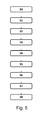
- Fig. 5 shows a flowchart over the different steps S0-S8 for providing a channel for a buried cable installation, wherein step S0 and S8 are optional steps.
- the first optional step S0 is to, before arranging the first bottom portion 100a, creating a ditch in which the channel may be arranged.
- this step is an optional step as being a "buried cable” not necessarily means that the cable needs to be vertically lower displaced relative the surrounding surface of the ground. As discussed above, it merely means that the channel is covered by a particulate material.
- step S1 comprise arranging the first channel portion 100a such that its longitudinal opening faces substantially upwardly. Consequently the base should face substantially downwardly.
- the second step is arranging S2 a second channel portion 100c so that its longitudinal opening also faces substantially upwardly and so that a first end opening portion 110 of the first channel portion 100a is interconnected with a second end opening portion 112 of the second channel portion 100c, as described in relation to Fig. 4 .
- the fourth step is introducing S3 a cable or pipe in the longitudinal opening of the first and second channel portions. This is a vastly simpler than pulling the cable through an already closed channel. The cable or pipe may now be lifted in, or even pushed into the open channel portions. In other embodiments, it is possible to arrange a plurality of so called bottom channel portions before introducing the cable into the channel portions.
- next step is arranging S4 a third channel portion 100b, with its longitudinal opening facing substantially downwardly and longitudinally and laterally aligned with one of the first and second channel portions 100a;100c. Thereby, at least a portion of the channel is substantially covered.
- the next step is interconnecting S5 the third channel portion 100b, along the longitudinal direction, with said one of the first and second channel portions 100a;100c,.
- the next step is arranging S6 a fourth channel portion 100d, with its longitudinal opening facing substantially downwardly and longitudinally and laterally aligned with the other one of the first and second channel portions 100c; 100a.
- an optional step is burying the channel in a particulate material, such as sand, gravel, macadam, clay, soil or the like.
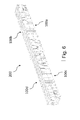
- Fig. 6 further merely shows an illustration a channel comprising four channel portions 100a, 100b, 100c, 100d interconnected as described above.
- Fig. 6 there are two so called bottom channel portions 100a, 100c and two so called top channel portions 100b, 100d.
- all four channel portions are identical.
- the bottom channel portions are identical to each other and the top channel portions are identical to each other but different from the bottom channel portions.
- the bottom channels must however always be compatible to be arranged open long side to open long side with a top portion.
- the top channel portions and the bottom channel portions shall be interconnectable with other top channel portions and bottom channel portions respectively in an end-to-end relationship as described above.
Landscapes
- Engineering & Computer Science (AREA)
- Architecture (AREA)
- Civil Engineering (AREA)
- Structural Engineering (AREA)
- Laying Of Electric Cables Or Lines Outside (AREA)
Priority Applications (1)
| Application Number | Priority Date | Filing Date | Title |
|---|---|---|---|
| EP20120190164 EP2725670B1 (de) | 2012-10-26 | 2012-10-26 | Kanalabschnitt zur Herstellung eines Kanals, Kanal und Verfahren zur Bereitstellung und Herstellung eines derartigen Kanals |
Applications Claiming Priority (1)
| Application Number | Priority Date | Filing Date | Title |
|---|---|---|---|
| EP20120190164 EP2725670B1 (de) | 2012-10-26 | 2012-10-26 | Kanalabschnitt zur Herstellung eines Kanals, Kanal und Verfahren zur Bereitstellung und Herstellung eines derartigen Kanals |
Publications (2)
| Publication Number | Publication Date |
|---|---|
| EP2725670A1 true EP2725670A1 (de) | 2014-04-30 |
| EP2725670B1 EP2725670B1 (de) | 2014-06-11 |
Family
ID=47325830
Family Applications (1)
| Application Number | Title | Priority Date | Filing Date |
|---|---|---|---|
| EP20120190164 Not-in-force EP2725670B1 (de) | 2012-10-26 | 2012-10-26 | Kanalabschnitt zur Herstellung eines Kanals, Kanal und Verfahren zur Bereitstellung und Herstellung eines derartigen Kanals |
Country Status (1)
| Country | Link |
|---|---|
| EP (1) | EP2725670B1 (de) |
Cited By (2)
| Publication number | Priority date | Publication date | Assignee | Title |
|---|---|---|---|---|
| EP3088786A1 (de) * | 2015-04-27 | 2016-11-02 | Polypipe Limited | Modulares mehrfachleitungssystem |
| ES2695452A1 (es) * | 2017-06-29 | 2019-01-04 | Unex Aparellaje Electrico Sl | Procedimiento de fabricación de una bandeja portacables de rejilla, y bandeja portacables de rejilla correspondiente |
Families Citing this family (1)
| Publication number | Priority date | Publication date | Assignee | Title |
|---|---|---|---|---|
| DE102021124737A1 (de) | 2021-09-24 | 2023-03-30 | Deere & Company | Kabelkanal |
Citations (5)
| Publication number | Priority date | Publication date | Assignee | Title |
|---|---|---|---|---|
| GB954230A (en) * | 1961-02-11 | 1964-04-02 | Deans And Lightalloys Ltd | Improved cable trough assembly |
| US6216746B1 (en) * | 2000-02-04 | 2001-04-17 | Hoffman Enclosures, Inc. | Lay-in wireway |
| WO2005045294A2 (en) * | 2003-02-22 | 2005-05-19 | Barry Howard | Duct unit for housing service cables, pipes and the like |
| DE202008009852U1 (de) * | 2008-07-23 | 2008-09-18 | Niedax Gmbh & Co. Kg | Kabelrinne |
| EP2369705A1 (de) * | 2010-02-03 | 2011-09-28 | Aiscan, S.L. | Bahnenmetall-ablagemodul zur kanalisierung von kabeln |
-
2012
- 2012-10-26 EP EP20120190164 patent/EP2725670B1/de not_active Not-in-force
Patent Citations (5)
| Publication number | Priority date | Publication date | Assignee | Title |
|---|---|---|---|---|
| GB954230A (en) * | 1961-02-11 | 1964-04-02 | Deans And Lightalloys Ltd | Improved cable trough assembly |
| US6216746B1 (en) * | 2000-02-04 | 2001-04-17 | Hoffman Enclosures, Inc. | Lay-in wireway |
| WO2005045294A2 (en) * | 2003-02-22 | 2005-05-19 | Barry Howard | Duct unit for housing service cables, pipes and the like |
| DE202008009852U1 (de) * | 2008-07-23 | 2008-09-18 | Niedax Gmbh & Co. Kg | Kabelrinne |
| EP2369705A1 (de) * | 2010-02-03 | 2011-09-28 | Aiscan, S.L. | Bahnenmetall-ablagemodul zur kanalisierung von kabeln |
Cited By (2)
| Publication number | Priority date | Publication date | Assignee | Title |
|---|---|---|---|---|
| EP3088786A1 (de) * | 2015-04-27 | 2016-11-02 | Polypipe Limited | Modulares mehrfachleitungssystem |
| ES2695452A1 (es) * | 2017-06-29 | 2019-01-04 | Unex Aparellaje Electrico Sl | Procedimiento de fabricación de una bandeja portacables de rejilla, y bandeja portacables de rejilla correspondiente |
Also Published As
| Publication number | Publication date |
|---|---|
| EP2725670B1 (de) | 2014-06-11 |
Similar Documents
| Publication | Publication Date | Title |
|---|---|---|
| US5463187A (en) | Flexible multi-duct conduit assembly | |
| US9964236B2 (en) | Modular conduit system | |
| US20210071785A1 (en) | Preformed Duct Assembly | |
| US9909708B1 (en) | Preventing disturbances of underground conduit | |
| EP2725670B1 (de) | Kanalabschnitt zur Herstellung eines Kanals, Kanal und Verfahren zur Bereitstellung und Herstellung eines derartigen Kanals | |
| CA3076835C (en) | Pipe protector | |
| JP3287770B2 (ja) | 地中埋設管路 | |
| US20110135392A1 (en) | Modular, scalable liquid management system | |
| US3977703A (en) | Multiple duct underground conduit | |
| EP3088617B1 (de) | Wand mit einem durchgang und verfahren zu dessen herstellung | |
| JPH11215675A (ja) | 埋設ケーブル保護部材 | |
| JP3505399B2 (ja) | 地中埋設容器の管路導入壁組立部材 | |
| JP2007255436A (ja) | 地下埋設多孔管路及びその布設方法 | |
| JP4142297B2 (ja) | 地中埋設管路 | |
| KR20120102946A (ko) | 관로구 방수 장치 | |
| EP3270026B1 (de) | Verfahren zur bereitstellung einer flüssigkeitsdichten verbindung zwischen teilen und struktur mit einer derartigen verbindung | |
| JP4279294B2 (ja) | 地中埋設管路の布設方法 | |
| US7099551B2 (en) | Cabling apparatus | |
| WO2005045294A2 (en) | Duct unit for housing service cables, pipes and the like | |
| WO2002054553A2 (en) | Cable installations and components therefor | |
| US20260117910A1 (en) | Couplers and adaptors for vapor mitigation implementations | |
| JP2002303380A (ja) | 地中埋設管路 | |
| JP4184896B2 (ja) | 配管構造 | |
| JP2022092696A (ja) | U字溝ブロック及びu字溝ブロック装置 | |
| JP3044243B2 (ja) | ケーブル地中敷設用管路 |
Legal Events
| Date | Code | Title | Description |
|---|---|---|---|
| GRAP | Despatch of communication of intention to grant a patent |
Free format text: ORIGINAL CODE: EPIDOSNIGR1 |
|
| GRAS | Grant fee paid |
Free format text: ORIGINAL CODE: EPIDOSNIGR3 |
|
| PUAI | Public reference made under article 153(3) epc to a published international application that has entered the european phase |
Free format text: ORIGINAL CODE: 0009012 |
|
| 17P | Request for examination filed |
Effective date: 20130520 |
|
| AK | Designated contracting states |
Kind code of ref document: A1 Designated state(s): AL AT BE BG CH CY CZ DE DK EE ES FI FR GB GR HR HU IE IS IT LI LT LU LV MC MK MT NL NO PL PT RO RS SE SI SK SM TR |
|
| GRAA | (expected) grant |
Free format text: ORIGINAL CODE: 0009210 |
|
| AK | Designated contracting states |
Kind code of ref document: B1 Designated state(s): AL AT BE BG CH CY CZ DE DK EE ES FI FR GB GR HR HU IE IS IT LI LT LU LV MC MK MT NL NO PL PT RO RS SE SI SK SM TR |
|
| REG | Reference to a national code |
Ref country code: GB Ref legal event code: FG4D |
|
| REG | Reference to a national code |
Ref country code: CH Ref legal event code: EP |
|
| REG | Reference to a national code |
Ref country code: IE Ref legal event code: FG4D |
|
| REG | Reference to a national code |
Ref country code: AT Ref legal event code: REF Ref document number: 672640 Country of ref document: AT Kind code of ref document: T Effective date: 20140715 |
|
| REG | Reference to a national code |
Ref country code: DE Ref legal event code: R096 Ref document number: 602012002047 Country of ref document: DE Effective date: 20140724 |
|
| REG | Reference to a national code |
Ref country code: SE Ref legal event code: TRGR |
|
| PG25 | Lapsed in a contracting state [announced via postgrant information from national office to epo] |
Ref country code: LT Free format text: LAPSE BECAUSE OF FAILURE TO SUBMIT A TRANSLATION OF THE DESCRIPTION OR TO PAY THE FEE WITHIN THE PRESCRIBED TIME-LIMIT Effective date: 20140611 Ref country code: GR Free format text: LAPSE BECAUSE OF FAILURE TO SUBMIT A TRANSLATION OF THE DESCRIPTION OR TO PAY THE FEE WITHIN THE PRESCRIBED TIME-LIMIT Effective date: 20140912 Ref country code: FI Free format text: LAPSE BECAUSE OF FAILURE TO SUBMIT A TRANSLATION OF THE DESCRIPTION OR TO PAY THE FEE WITHIN THE PRESCRIBED TIME-LIMIT Effective date: 20140611 |
|
| REG | Reference to a national code |
Ref country code: NO Ref legal event code: T2 Effective date: 20140611 |
|
| REG | Reference to a national code |
Ref country code: NL Ref legal event code: VDEP Effective date: 20140611 |
|
| REG | Reference to a national code |
Ref country code: AT Ref legal event code: MK05 Ref document number: 672640 Country of ref document: AT Kind code of ref document: T Effective date: 20140611 |
|
| REG | Reference to a national code |
Ref country code: LT Ref legal event code: MG4D |
|
| PG25 | Lapsed in a contracting state [announced via postgrant information from national office to epo] |
Ref country code: RS Free format text: LAPSE BECAUSE OF FAILURE TO SUBMIT A TRANSLATION OF THE DESCRIPTION OR TO PAY THE FEE WITHIN THE PRESCRIBED TIME-LIMIT Effective date: 20140611 Ref country code: LV Free format text: LAPSE BECAUSE OF FAILURE TO SUBMIT A TRANSLATION OF THE DESCRIPTION OR TO PAY THE FEE WITHIN THE PRESCRIBED TIME-LIMIT Effective date: 20140611 Ref country code: HR Free format text: LAPSE BECAUSE OF FAILURE TO SUBMIT A TRANSLATION OF THE DESCRIPTION OR TO PAY THE FEE WITHIN THE PRESCRIBED TIME-LIMIT Effective date: 20140611 |
|
| PG25 | Lapsed in a contracting state [announced via postgrant information from national office to epo] |
Ref country code: SK Free format text: LAPSE BECAUSE OF FAILURE TO SUBMIT A TRANSLATION OF THE DESCRIPTION OR TO PAY THE FEE WITHIN THE PRESCRIBED TIME-LIMIT Effective date: 20140611 Ref country code: ES Free format text: LAPSE BECAUSE OF FAILURE TO SUBMIT A TRANSLATION OF THE DESCRIPTION OR TO PAY THE FEE WITHIN THE PRESCRIBED TIME-LIMIT Effective date: 20140611 Ref country code: CZ Free format text: LAPSE BECAUSE OF FAILURE TO SUBMIT A TRANSLATION OF THE DESCRIPTION OR TO PAY THE FEE WITHIN THE PRESCRIBED TIME-LIMIT Effective date: 20140611 Ref country code: PT Free format text: LAPSE BECAUSE OF FAILURE TO SUBMIT A TRANSLATION OF THE DESCRIPTION OR TO PAY THE FEE WITHIN THE PRESCRIBED TIME-LIMIT Effective date: 20141013 Ref country code: RO Free format text: LAPSE BECAUSE OF FAILURE TO SUBMIT A TRANSLATION OF THE DESCRIPTION OR TO PAY THE FEE WITHIN THE PRESCRIBED TIME-LIMIT Effective date: 20140611 Ref country code: EE Free format text: LAPSE BECAUSE OF FAILURE TO SUBMIT A TRANSLATION OF THE DESCRIPTION OR TO PAY THE FEE WITHIN THE PRESCRIBED TIME-LIMIT Effective date: 20140611 |
|
| PG25 | Lapsed in a contracting state [announced via postgrant information from national office to epo] |
Ref country code: NL Free format text: LAPSE BECAUSE OF FAILURE TO SUBMIT A TRANSLATION OF THE DESCRIPTION OR TO PAY THE FEE WITHIN THE PRESCRIBED TIME-LIMIT Effective date: 20140611 Ref country code: AT Free format text: LAPSE BECAUSE OF FAILURE TO SUBMIT A TRANSLATION OF THE DESCRIPTION OR TO PAY THE FEE WITHIN THE PRESCRIBED TIME-LIMIT Effective date: 20140611 Ref country code: PL Free format text: LAPSE BECAUSE OF FAILURE TO SUBMIT A TRANSLATION OF THE DESCRIPTION OR TO PAY THE FEE WITHIN THE PRESCRIBED TIME-LIMIT Effective date: 20140611 Ref country code: IS Free format text: LAPSE BECAUSE OF FAILURE TO SUBMIT A TRANSLATION OF THE DESCRIPTION OR TO PAY THE FEE WITHIN THE PRESCRIBED TIME-LIMIT Effective date: 20141011 |
|
| REG | Reference to a national code |
Ref country code: DE Ref legal event code: R097 Ref document number: 602012002047 Country of ref document: DE |
|
| PLBE | No opposition filed within time limit |
Free format text: ORIGINAL CODE: 0009261 |
|
| STAA | Information on the status of an ep patent application or granted ep patent |
Free format text: STATUS: NO OPPOSITION FILED WITHIN TIME LIMIT |
|
| PG25 | Lapsed in a contracting state [announced via postgrant information from national office to epo] |
Ref country code: IT Free format text: LAPSE BECAUSE OF FAILURE TO SUBMIT A TRANSLATION OF THE DESCRIPTION OR TO PAY THE FEE WITHIN THE PRESCRIBED TIME-LIMIT Effective date: 20140611 Ref country code: DK Free format text: LAPSE BECAUSE OF FAILURE TO SUBMIT A TRANSLATION OF THE DESCRIPTION OR TO PAY THE FEE WITHIN THE PRESCRIBED TIME-LIMIT Effective date: 20140611 |
|
| 26N | No opposition filed |
Effective date: 20150312 |
|
| PG25 | Lapsed in a contracting state [announced via postgrant information from national office to epo] |
Ref country code: LU Free format text: LAPSE BECAUSE OF FAILURE TO SUBMIT A TRANSLATION OF THE DESCRIPTION OR TO PAY THE FEE WITHIN THE PRESCRIBED TIME-LIMIT Effective date: 20141026 Ref country code: MC Free format text: LAPSE BECAUSE OF FAILURE TO SUBMIT A TRANSLATION OF THE DESCRIPTION OR TO PAY THE FEE WITHIN THE PRESCRIBED TIME-LIMIT Effective date: 20140611 |
|
| REG | Reference to a national code |
Ref country code: DE Ref legal event code: R097 Ref document number: 602012002047 Country of ref document: DE Effective date: 20150312 |
|
| REG | Reference to a national code |
Ref country code: IE Ref legal event code: MM4A |
|
| PG25 | Lapsed in a contracting state [announced via postgrant information from national office to epo] |
Ref country code: SI Free format text: LAPSE BECAUSE OF FAILURE TO SUBMIT A TRANSLATION OF THE DESCRIPTION OR TO PAY THE FEE WITHIN THE PRESCRIBED TIME-LIMIT Effective date: 20140611 |
|
| REG | Reference to a national code |
Ref country code: FR Ref legal event code: ST Effective date: 20150630 |
|
| PG25 | Lapsed in a contracting state [announced via postgrant information from national office to epo] |
Ref country code: FR Free format text: LAPSE BECAUSE OF NON-PAYMENT OF DUE FEES Effective date: 20141031 |
|
| PG25 | Lapsed in a contracting state [announced via postgrant information from national office to epo] |
Ref country code: IE Free format text: LAPSE BECAUSE OF NON-PAYMENT OF DUE FEES Effective date: 20141026 |
|
| PGFP | Annual fee paid to national office [announced via postgrant information from national office to epo] |
Ref country code: NO Payment date: 20151006 Year of fee payment: 4 |
|
| REG | Reference to a national code |
Ref country code: CH Ref legal event code: PL |
|
| PG25 | Lapsed in a contracting state [announced via postgrant information from national office to epo] |
Ref country code: BG Free format text: LAPSE BECAUSE OF FAILURE TO SUBMIT A TRANSLATION OF THE DESCRIPTION OR TO PAY THE FEE WITHIN THE PRESCRIBED TIME-LIMIT Effective date: 20140611 Ref country code: CY Free format text: LAPSE BECAUSE OF FAILURE TO SUBMIT A TRANSLATION OF THE DESCRIPTION OR TO PAY THE FEE WITHIN THE PRESCRIBED TIME-LIMIT Effective date: 20140611 |
|
| PG25 | Lapsed in a contracting state [announced via postgrant information from national office to epo] |
Ref country code: MT Free format text: LAPSE BECAUSE OF FAILURE TO SUBMIT A TRANSLATION OF THE DESCRIPTION OR TO PAY THE FEE WITHIN THE PRESCRIBED TIME-LIMIT Effective date: 20140611 Ref country code: LI Free format text: LAPSE BECAUSE OF NON-PAYMENT OF DUE FEES Effective date: 20151031 Ref country code: HU Free format text: LAPSE BECAUSE OF FAILURE TO SUBMIT A TRANSLATION OF THE DESCRIPTION OR TO PAY THE FEE WITHIN THE PRESCRIBED TIME-LIMIT; INVALID AB INITIO Effective date: 20121026 Ref country code: CH Free format text: LAPSE BECAUSE OF NON-PAYMENT OF DUE FEES Effective date: 20151031 Ref country code: TR Free format text: LAPSE BECAUSE OF FAILURE TO SUBMIT A TRANSLATION OF THE DESCRIPTION OR TO PAY THE FEE WITHIN THE PRESCRIBED TIME-LIMIT Effective date: 20140611 Ref country code: BE Free format text: LAPSE BECAUSE OF FAILURE TO SUBMIT A TRANSLATION OF THE DESCRIPTION OR TO PAY THE FEE WITHIN THE PRESCRIBED TIME-LIMIT Effective date: 20140611 |
|
| PGFP | Annual fee paid to national office [announced via postgrant information from national office to epo] |
Ref country code: DE Payment date: 20161004 Year of fee payment: 5 |
|
| PGFP | Annual fee paid to national office [announced via postgrant information from national office to epo] |
Ref country code: SE Payment date: 20161003 Year of fee payment: 5 |
|
| REG | Reference to a national code |
Ref country code: NO Ref legal event code: MMEP |
|
| PG25 | Lapsed in a contracting state [announced via postgrant information from national office to epo] |
Ref country code: SM Free format text: LAPSE BECAUSE OF FAILURE TO SUBMIT A TRANSLATION OF THE DESCRIPTION OR TO PAY THE FEE WITHIN THE PRESCRIBED TIME-LIMIT Effective date: 20140611 |
|
| GBPC | Gb: european patent ceased through non-payment of renewal fee |
Effective date: 20161026 |
|
| PG25 | Lapsed in a contracting state [announced via postgrant information from national office to epo] |
Ref country code: GB Free format text: LAPSE BECAUSE OF NON-PAYMENT OF DUE FEES Effective date: 20161026 Ref country code: NO Free format text: LAPSE BECAUSE OF NON-PAYMENT OF DUE FEES Effective date: 20161031 |
|
| REG | Reference to a national code |
Ref country code: DE Ref legal event code: R119 Ref document number: 602012002047 Country of ref document: DE |
|
| REG | Reference to a national code |
Ref country code: SE Ref legal event code: EUG |
|
| PG25 | Lapsed in a contracting state [announced via postgrant information from national office to epo] |
Ref country code: MK Free format text: LAPSE BECAUSE OF FAILURE TO SUBMIT A TRANSLATION OF THE DESCRIPTION OR TO PAY THE FEE WITHIN THE PRESCRIBED TIME-LIMIT Effective date: 20140611 |
|
| PG25 | Lapsed in a contracting state [announced via postgrant information from national office to epo] |
Ref country code: DE Free format text: LAPSE BECAUSE OF NON-PAYMENT OF DUE FEES Effective date: 20180501 |
|
| PG25 | Lapsed in a contracting state [announced via postgrant information from national office to epo] |
Ref country code: SE Free format text: LAPSE BECAUSE OF NON-PAYMENT OF DUE FEES Effective date: 20171027 |
|
| PG25 | Lapsed in a contracting state [announced via postgrant information from national office to epo] |
Ref country code: AL Free format text: LAPSE BECAUSE OF FAILURE TO SUBMIT A TRANSLATION OF THE DESCRIPTION OR TO PAY THE FEE WITHIN THE PRESCRIBED TIME-LIMIT Effective date: 20140611 |