EP2728112A2 - Dispositif de transport d'une charge lors du creusement d'un tunnel - Google Patents
Dispositif de transport d'une charge lors du creusement d'un tunnel Download PDFInfo
- Publication number
- EP2728112A2 EP2728112A2 EP13187734.2A EP13187734A EP2728112A2 EP 2728112 A2 EP2728112 A2 EP 2728112A2 EP 13187734 A EP13187734 A EP 13187734A EP 2728112 A2 EP2728112 A2 EP 2728112A2
- Authority
- EP
- European Patent Office
- Prior art keywords
- support frame
- altitude
- track
- chassis
- side supports
- Prior art date
- Legal status (The legal status is an assumption and is not a legal conclusion. Google has not performed a legal analysis and makes no representation as to the accuracy of the status listed.)
- Granted
Links
Images


Classifications
-
- E—FIXED CONSTRUCTIONS
- E21—EARTH OR ROCK DRILLING; MINING
- E21D—SHAFTS; TUNNELS; GALLERIES; LARGE UNDERGROUND CHAMBERS
- E21D11/00—Lining tunnels, galleries or other underground cavities, e.g. large underground chambers; Linings therefor; Making such linings in situ, e.g. by assembling
- E21D11/40—Devices or apparatus specially adapted for handling or placing units of linings or supporting units for tunnels or galleries
-
- E—FIXED CONSTRUCTIONS
- E21—EARTH OR ROCK DRILLING; MINING
- E21F—SAFETY DEVICES, TRANSPORT, FILLING-UP, RESCUE, VENTILATION, OR DRAINING IN OR OF MINES OR TUNNELS
- E21F13/00—Transport specially adapted to underground conditions
- E21F13/006—Equipment transport systems
Definitions
- the invention relates to a device for conveying cargo during tunneling according to the preamble of claim 1.
- Such a device is off JP 5-33600 (A ) known.
- the known device for conveying, for example, by Tuebbinge formed charge during tunneling has a support frame on which the charge to be transported can be positioned, and a number of spaced at a track pitch chassis segments which are connected to the support frame and with which the support frame moved is.
- the chassis segments are connected in a fixed relative positioning with the support frame.
- a device for conveying cargo during tunneling in which a provided for conveying cargo support frame is slidably mounted on a suspended in the ceiling region of a tunnel rail, so that below the support frame a working space remains free.
- the invention has for its object to provide a device of the type mentioned, with which in a space-saving manner and relatively large-volume charge in tunneling is efficiently conveyed.
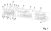
- Fig. 1 shows a perspective view of a partially cut tunnel wall 1, which is completed in the context of a tunneling so far that trained as a self-propelled trolley 2 embodiments of devices according to the invention in the longitudinal direction of a lined tunnel wall 1 tunnel can be moved.
- Each trolley 2 has a trained with a suitably rectangular base planar support frame 3, on which in the embodiments according to Fig. 1 in each case a container 4 is arranged.
- Each container 4 is open on its side facing away from the support frame 3, so that it can be loaded with charge to be conveyed during tunneling.
- a number of angle guide parts 5 of an adjusting device is mounted, mounted on the one hand in the plane of the support frame 3 at right angles to the long edge sides displaceable, and which are arranged to the other, each a side support 6 of the adjustment in one slidably received to the plane of the support racks 3 perpendicular direction.
- Each side support 6 carries at a remote from the support frame 3 foot a chassis segment 7.
- the chassis segments 7 are in accordance with the arrangement of the trolley 2 with a bottom portion of the tunnel wall 1 in contact and adapted to each trolley 2 in the longitudinal direction of the lined tunnel wall 1 tunnel is movable.
- each trolley 2 with appropriate positioning of the angle guide parts 5 and the side supports 6 with its support frame 3 in an upper altitude and with its chassis segments 7 at a wide track pitch or with its support frame 3 in a lower Altitude and with its chassis segments 7 in a narrow track pitch is adjustable so that, as in Fig. 1 shown in the middle and on the right side pairs of trolley 2, each along a common central track, which runs along the deepest region of the tunnel wall 1, moving trolley 2 can be nested in each other.
- a power supply unit 8 is mounted, with which the chassis segments 7 of a trolley 2 for an autonomous process each trolley 2 can be acted upon with energy.
- Fig. 2 shows in a perspective view of a trolley 2 as an embodiment of a device according to the invention according to Fig. 1 with the support frame 3 in an upper altitude and with the chassis segments 7 in a wide track spacing.
- immersing arms 9 of the angle guide parts 5 are extended with a Ausfährabsacrificing from the support frame 3 in the support frame 3, while the chassis segments 7 opposite free ends of the side supports 6 within perpendicular to the immersion arms 9 aligned guide arms 10 of the angle guide parts. 5 are arranged.
- the immersion arms 9 of the angle guide members 5 are also provided with locking recesses 13 to lock the angle guide members 5 in different lateral positions with respect to the support frame 3. Accordingly, 6 locking recesses 13 are arranged in the free ends of the side supports 6 opposite and the chassis segments 7 facing foot ends of the side supports, which are aligned.
- Fig. 2 recognize that the angle guide members 5 are rigidly connected to each other via connecting rods 14, so that when moving an angle guide member 5 with this angle guide member 5 via the connecting rod 14 connected further angle guide member 5 is moved. Accordingly, arranged along a long edge side of the support frame 3 side supports 6 are connected to each other at the foot via another connecting rod 14 to accommodate in particular on the side supports 6 in the upper elevation of the support frame 3 in the longitudinal direction of the chassis 3 acting bending forces and to avoid vibrations distribute all over this further connecting rod 14 coupled side supports 6.
- each chassis segment 7 is equipped with a number of rollers 15 whose axes are aligned so that each transport carriage 2 is movable in a transport direction.
- a multiple cameras 16 having lane keeping device is present.
- a safety scanner 17 is attached to each peripheral chassis segment 7.
- the safety scanner 17 cooperate with emergency braking devices 18, which are provided on the inside of the chassis segments 7 in the illustrated embodiment.
- each side support 6 and the chassis segment 7 connected to the side support 6 are connected to each other via a connecting joint 19 of a connecting joint arrangement, which is set up such that the chassis segments 7 are pivotable in a plane transverse to the support frame 3 at each set track spacing of the chassis segments 7 a proper contact of the rollers 15 with the ground in the form of in Fig. 2 To ensure tunnel wall 1 not shown.
- Fig. 3 shows in a perspective view of a trolley 2 in the embodiment according to Fig. 1 with the support frame 3 in a lower altitude and the chassis segments 7 in a narrow track pitch.
- the dipping arms 9 of the angle guide members 5 are substantially completely inserted into the support frame 3 and locked by soarretieranlenkstange 20 of Soarretierstoffn, while the free ends of the side supports 6 have now leaked from the guide arms 10 and survive this, so that the support frame 3 relative to the arrangement according to Fig. 2 is lowered and the foot ends of the side supports 6 are close to the guide arms 10.
- Fig. 4 shows in an end view two transport carriage 2 within a tunnel wall 1, wherein a trolley 2 is set in an upper altitude and with a wide track pitch and the other trolley 2 in a lower elevation and with a narrow track pitch.
- the two altitudes and the two track distances are set up so that the set in the lower altitude and the narrow track distance Dolly 2 substantially fills the clear width and the clear height of the set in an upper altitude and at a wide track distance trolley 2 and covered by this covered along one of two trolleys 2 shared center track is movable without obstruction.
- Fig. 4 clearly see that the landing gear segments 2 are aligned at different track distances for a full-surface contact of the rollers 15 with the tunnel wall 1 by means of the connecting joints 19 at different angles to the side supports 6.
- the lower altitude and the narrow track spacing are set up so that even a small vehicle 21 can drive obstructed by a correspondingly set transport carriage 2 covered along the center track.
- Fig. 5 shows in a perspective view of a loading station 22, in which a Fig. 1 to Fig. 4 explained in more detail Dolly 2 is retracted in a setting with the support frame 3 in the upper altitude and the chassis segments 7 in a wide track pitch.
- the container 4 is typically equipped with a tubbing 23 as to be transported in tunneling charge, the with a crane unit 24, as explained in more detail below, from the container 4 can be removed.
- the crane unit 24 is movable along rails 25, which is arranged at a distance from a working platform 26.
- the work platform 26 has a receiving area, in the representation in accordance with Fig. 5 the trolley 2 is retracted.
- a scissors table 27 is arranged, which has a support surface 28 which is raised by means of a scissor assembly 29 relative to a movable support frame 30 and lowered again.
- Fig. 6 shows the arrangement according to Fig. 5 with a view of the chassis segments 7 facing bottom of the working platform 26 with the trolley 2 in a setting with the support frame 3 in the lower altitude and the chassis segments 7 in the narrow track pitch.
- the lower altitude was based on the arrangement according to Fig. 5 assumed that after raising the support surface 28 of the scissors table 27 to rest on the support frame 3 by moving thecheznarretieranlenkstangen 11 and the Seitarretieranlenkstangen 20, the support frame 3 and the angle guide parts 5 are unlocked such that the support frame 3 by lowering the support surface 28 in the direction of the support frame 30 in the lower altitude can be transferred and the angle guide members 5 are inserted by the action of attached to the working platform 26 Einschiebezylinder 31 in the support frame 3.
- the crane unit 24 can be moved over the container 4, so that with a mounted on the crane unit 24 tubbing manipulator 32 of the container 4 lying in the representation according to Fig. 6 invisible tubbing 23 can be removed.
- Fig. 7 shows a arranged on a track 1 'Dolly 2 in a setting with the support frame 3 in the lower altitude and the chassis segments 7 in the narrow track pitch in a direction opposite to the direction of advance from the loading station 22 spaced Abkippstation 33.
- the Abkippstation 33 is equipped with Abkippzylinder strictly strictly 34 , which have extendable actuating rods 35 with which the container 4 relative to the support frame 33 along a short edge of the support frame 3 pivot axis is so far raised, so that the container 4 is placed obliquely relative to the support frame 3 and in the container. 4 existing charge at an open container flap 36 via a chute 37 into a receiving space 38 can be transferred. In this case, the container 4 is supported on an abutment 39 formed in the region of the chute 37.
- Fig. 7 the illustration according to Fig. 7 can be seen that the Abkippstation 33 is equipped with a lifting table 40, with which, as explained in more detail below, the support frame 3 of the in Fig. 7 shown lower altitude is movable back to an upper altitude.
- Fig. 8 shows in a perspective view the Abkippstation 33 according to Fig. 7 without a trolley 2.
- the representation according to Fig. 8 can be seen that the lifting table 40 with a number of lifting cylinders 41 relative to a bearing bed 42 can be raised and lowered and provided with a number of Ausdschreibzylindern 43, with which the angle guide parts 5 for transferring the Chassis segments 7 are displaced from the narrow track spacing in a wide track pitch.
- Fig. 9 shows a perspective view of a Abkippstation 33 according to Fig. 7 and Fig. 8 arranged dolly 2, which is now set with the support frame 3 in the upper altitude and the chassis segments 7 in the wide track pitch.
- the trolley 2 is now back with a in Fig. 9 Tübbing 23, not shown, can be charged as a charge in order to convey the tubbing 23 back to a loading station 22.
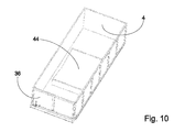
- Fig. 10 shows a perspective view of a container 4 for a trolley 2 with a curved Tübbingauflage 44, which is positioned for placing a tubbing 44 with a tubbing support surface in the direction of the open side of the container 4 facing. In this positioning, a tubbing 23 can be placed on the tubbing support 44.
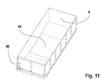
- Fig. 11 shows in a perspective view a container 4 accordingly Fig. 10 with the tubbing support 44 in a relation to the positioning according to Fig. 10 such rotated positioning that in Fig. 11 no longer visible Tübbingauflage 44 now in the direction of the bottom of the container 4 and is protected from damage during transport of further cargo, especially in the form of overburden in tunneling.
Landscapes
- Engineering & Computer Science (AREA)
- Mining & Mineral Resources (AREA)
- Life Sciences & Earth Sciences (AREA)
- General Life Sciences & Earth Sciences (AREA)
- Geochemistry & Mineralogy (AREA)
- Geology (AREA)
- Mechanical Engineering (AREA)
- Architecture (AREA)
- Civil Engineering (AREA)
- Structural Engineering (AREA)
- Lining And Supports For Tunnels (AREA)
- Warehouses Or Storage Devices (AREA)
Applications Claiming Priority (1)
| Application Number | Priority Date | Filing Date | Title |
|---|---|---|---|
| DE102012219815.6A DE102012219815A1 (de) | 2012-10-30 | 2012-10-30 | Vorrichtung zum Befördern von Ladung beim Tunnelvortrieb |
Publications (3)
| Publication Number | Publication Date |
|---|---|
| EP2728112A2 true EP2728112A2 (fr) | 2014-05-07 |
| EP2728112A3 EP2728112A3 (fr) | 2017-02-22 |
| EP2728112B1 EP2728112B1 (fr) | 2018-11-28 |
Family
ID=49322258
Family Applications (1)
| Application Number | Title | Priority Date | Filing Date |
|---|---|---|---|
| EP13187734.2A Active EP2728112B1 (fr) | 2012-10-30 | 2013-10-08 | Dispositif de transport d'une charge lors du creusement d'un tunnel |
Country Status (3)
| Country | Link |
|---|---|
| EP (1) | EP2728112B1 (fr) |
| DE (1) | DE102012219815A1 (fr) |
| ES (1) | ES2710248T3 (fr) |
Families Citing this family (1)
| Publication number | Priority date | Publication date | Assignee | Title |
|---|---|---|---|---|
| CN111483920B (zh) * | 2020-04-26 | 2021-08-20 | 扎赉诺尔煤业有限责任公司 | 自吊式液压支架运输机 |
Citations (2)
| Publication number | Priority date | Publication date | Assignee | Title |
|---|---|---|---|---|
| JPH0533600A (ja) | 1991-07-26 | 1993-02-09 | Fujita Corp | シールド工事用車両 |
| DE10242574A1 (de) | 2002-09-11 | 2004-03-18 | Max Bögl Bauunternehmung GmbH & Co. KG | Verfahren zum Herstellen eines Tunnels und Hängebahn |
Family Cites Families (6)
| Publication number | Priority date | Publication date | Assignee | Title |
|---|---|---|---|---|
| GB120269A (en) * | 1917-11-06 | 1918-11-06 | Walter Lindley | Portable Hoisting Apparatus for use in Mines, Tunnels and the like. |
| CH482873A (de) * | 1968-11-25 | 1969-12-15 | Mecana S A Schmerikon | Einrichtung zum Verlegen von Dichtungs- und/oder Verkleidungsmaterialbahnen auf Tunnelwände |
| DE1924749A1 (de) * | 1969-05-14 | 1970-11-26 | Isolier Und Terrassenbau Gmbh | Maschine zum Aufbringen von in Rollen vorliegenden Bahnen |
| CH685832A5 (de) * | 1992-07-03 | 1995-10-13 | Paul Vogt | Vorrichtung zum Auskleiden von Tunnelflächen mit Folienbahnen. |
| JPH09272433A (ja) * | 1996-04-09 | 1997-10-21 | Kajima Corp | セグメント搬送用無人車の走行安定用車輪機構 |
| DE202007002168U1 (de) * | 2006-06-28 | 2007-06-28 | Skumtech As | Vorrichtung für Tunnelarbeiten |
-
2012
- 2012-10-30 DE DE102012219815.6A patent/DE102012219815A1/de not_active Withdrawn
-
2013
- 2013-10-08 EP EP13187734.2A patent/EP2728112B1/fr active Active
- 2013-10-08 ES ES13187734T patent/ES2710248T3/es active Active
Patent Citations (2)
| Publication number | Priority date | Publication date | Assignee | Title |
|---|---|---|---|---|
| JPH0533600A (ja) | 1991-07-26 | 1993-02-09 | Fujita Corp | シールド工事用車両 |
| DE10242574A1 (de) | 2002-09-11 | 2004-03-18 | Max Bögl Bauunternehmung GmbH & Co. KG | Verfahren zum Herstellen eines Tunnels und Hängebahn |
Also Published As
| Publication number | Publication date |
|---|---|
| DE102012219815A1 (de) | 2014-06-12 |
| ES2710248T3 (es) | 2019-04-23 |
| EP2728112A3 (fr) | 2017-02-22 |
| EP2728112B1 (fr) | 2018-11-28 |
Similar Documents
| Publication | Publication Date | Title |
|---|---|---|
| EP2576908B1 (fr) | Combinaison de véhicules pour le transport de rails | |
| DE2130968C2 (de) | Vorrichtung zum Verladen einer Fracht in ein Flugzeug5 | |
| EP1980474B1 (fr) | Skid destiné au transport d'un objet et station de transmission pour des tels skids | |
| DE202013102199U1 (de) | Trailerzuganhänger | |
| DE3136687A1 (de) | System, betriebsverfahren und vorrichtungen zum gleichzeitigen und rangierfreien umschlag zwischen schiene und schiene sowie strasse und schiene | |
| WO2008046728A1 (fr) | Chariot de transport relié au sol, en particulier pour le transport de conteneurs | |
| EP2418149A2 (fr) | Guidage latéral, groupe de guidage latéral et plafond de soute | |
| DE102017102930B4 (de) | Hebevorrichtung und Anlage zum Transportieren von Stückgut | |
| EP0276646B1 (fr) | Appareillage pour la dépose ou la pose ainsi que le transport des tronçons assemblés de la voie | |
| EP2096054B1 (fr) | Dispositif de manipulation pour marchandises au détail, en particulier cargo | |
| EP2484607B1 (fr) | Dispositif de transport et installation de transport équipée de ce dispositif | |
| EP3392125A1 (fr) | Procédé et système de transport destinés au transport simultané de pièces à usiner allongées et travail dans une ligne de production | |
| DE102017104751B4 (de) | Transportvorrichtung | |
| EP2728112B1 (fr) | Dispositif de transport d'une charge lors du creusement d'un tunnel | |
| EP3271514B1 (fr) | Fixation du chargement d'un wagon de transport d'aiguilles | |
| EP3359736B1 (fr) | Dispositif de chargement et de déchargement d'un tronçon de voie ferrée, en particulier d'un aiguillage | |
| DE102008036067A1 (de) | Logistiksystem | |
| DE102012104235B4 (de) | Verriegelungseinrichtung zum Sichern und/oder Führen mindestens eines Frachtstücks | |
| EP0438998B1 (fr) | Voiture de transport, en particulier voiture à bas niveau, ainsi que méthode pour le chargement et le déchargement de ladite voiture | |
| EP3535455B1 (fr) | Véhicule ferroviaire comprenant des rails pour une grue à portique | |
| DE102014110521B4 (de) | Bearbeitungsanlage für Baueinheiten sowie Verwendung einer Bearbeitungsanlage | |
| DE1455054C3 (fr) | ||
| DE102025126229A1 (de) | Vorrichtung zum transport von gütern im tunnelvortrieb | |
| DE1605104C3 (de) | Rahmen fur den Transport von Langgut | |
| EP0623547A1 (fr) | Système de travail et de transport mobile |
Legal Events
| Date | Code | Title | Description |
|---|---|---|---|
| PUAI | Public reference made under article 153(3) epc to a published international application that has entered the european phase |
Free format text: ORIGINAL CODE: 0009012 |
|
| 17P | Request for examination filed |
Effective date: 20131008 |
|
| AK | Designated contracting states |
Kind code of ref document: A2 Designated state(s): AL AT BE BG CH CY CZ DE DK EE ES FI FR GB GR HR HU IE IS IT LI LT LU LV MC MK MT NL NO PL PT RO RS SE SI SK SM TR |
|
| AX | Request for extension of the european patent |
Extension state: BA ME |
|
| PUAL | Search report despatched |
Free format text: ORIGINAL CODE: 0009013 |
|
| AK | Designated contracting states |
Kind code of ref document: A3 Designated state(s): AL AT BE BG CH CY CZ DE DK EE ES FI FR GB GR HR HU IE IS IT LI LT LU LV MC MK MT NL NO PL PT RO RS SE SI SK SM TR |
|
| AX | Request for extension of the european patent |
Extension state: BA ME |
|
| RIC1 | Information provided on ipc code assigned before grant |
Ipc: E21D 11/40 20060101AFI20170117BHEP Ipc: E21F 13/00 20060101ALI20170117BHEP |
|
| STAA | Information on the status of an ep patent application or granted ep patent |
Free format text: STATUS: REQUEST FOR EXAMINATION WAS MADE |
|
| 17P | Request for examination filed |
Effective date: 20170724 |
|
| RBV | Designated contracting states (corrected) |
Designated state(s): AL AT BE BG CH CY CZ DE DK EE ES FI FR GB GR HR HU IE IS IT LI LT LU LV MC MK MT NL NO PL PT RO RS SE SI SK SM TR |
|
| GRAP | Despatch of communication of intention to grant a patent |
Free format text: ORIGINAL CODE: EPIDOSNIGR1 |
|
| STAA | Information on the status of an ep patent application or granted ep patent |
Free format text: STATUS: GRANT OF PATENT IS INTENDED |
|
| INTG | Intention to grant announced |
Effective date: 20180629 |
|
| GRAJ | Information related to disapproval of communication of intention to grant by the applicant or resumption of examination proceedings by the epo deleted |
Free format text: ORIGINAL CODE: EPIDOSDIGR1 |
|
| STAA | Information on the status of an ep patent application or granted ep patent |
Free format text: STATUS: REQUEST FOR EXAMINATION WAS MADE |
|
| GRAP | Despatch of communication of intention to grant a patent |
Free format text: ORIGINAL CODE: EPIDOSNIGR1 |
|
| STAA | Information on the status of an ep patent application or granted ep patent |
Free format text: STATUS: GRANT OF PATENT IS INTENDED |
|
| INTC | Intention to grant announced (deleted) | ||
| INTG | Intention to grant announced |
Effective date: 20180810 |
|
| GRAS | Grant fee paid |
Free format text: ORIGINAL CODE: EPIDOSNIGR3 |
|
| GRAA | (expected) grant |
Free format text: ORIGINAL CODE: 0009210 |
|
| STAA | Information on the status of an ep patent application or granted ep patent |
Free format text: STATUS: THE PATENT HAS BEEN GRANTED |
|
| AK | Designated contracting states |
Kind code of ref document: B1 Designated state(s): AL AT BE BG CH CY CZ DE DK EE ES FI FR GB GR HR HU IE IS IT LI LT LU LV MC MK MT NL NO PL PT RO RS SE SI SK SM TR |
|
| REG | Reference to a national code |
Ref country code: CH Ref legal event code: EP |
|
| REG | Reference to a national code |
Ref country code: AT Ref legal event code: REF Ref document number: 1070474 Country of ref document: AT Kind code of ref document: T Effective date: 20181215 |
|
| REG | Reference to a national code |
Ref country code: IE Ref legal event code: FG4D Free format text: LANGUAGE OF EP DOCUMENT: GERMAN |
|
| REG | Reference to a national code |
Ref country code: DE Ref legal event code: R096 Ref document number: 502013011707 Country of ref document: DE |
|
| REG | Reference to a national code |
Ref country code: CH Ref legal event code: NV Representative=s name: MOINAS AND SAVOYE SARL, CH |
|
| REG | Reference to a national code |
Ref country code: NL Ref legal event code: MP Effective date: 20181128 |
|
| REG | Reference to a national code |
Ref country code: LT Ref legal event code: MG4D |
|
| REG | Reference to a national code |
Ref country code: ES Ref legal event code: FG2A Ref document number: 2710248 Country of ref document: ES Kind code of ref document: T3 Effective date: 20190423 |
|
| PG25 | Lapsed in a contracting state [announced via postgrant information from national office to epo] |
Ref country code: FI Free format text: LAPSE BECAUSE OF FAILURE TO SUBMIT A TRANSLATION OF THE DESCRIPTION OR TO PAY THE FEE WITHIN THE PRESCRIBED TIME-LIMIT Effective date: 20181128 Ref country code: IS Free format text: LAPSE BECAUSE OF FAILURE TO SUBMIT A TRANSLATION OF THE DESCRIPTION OR TO PAY THE FEE WITHIN THE PRESCRIBED TIME-LIMIT Effective date: 20190328 Ref country code: BG Free format text: LAPSE BECAUSE OF FAILURE TO SUBMIT A TRANSLATION OF THE DESCRIPTION OR TO PAY THE FEE WITHIN THE PRESCRIBED TIME-LIMIT Effective date: 20190228 Ref country code: LT Free format text: LAPSE BECAUSE OF FAILURE TO SUBMIT A TRANSLATION OF THE DESCRIPTION OR TO PAY THE FEE WITHIN THE PRESCRIBED TIME-LIMIT Effective date: 20181128 Ref country code: HR Free format text: LAPSE BECAUSE OF FAILURE TO SUBMIT A TRANSLATION OF THE DESCRIPTION OR TO PAY THE FEE WITHIN THE PRESCRIBED TIME-LIMIT Effective date: 20181128 Ref country code: LV Free format text: LAPSE BECAUSE OF FAILURE TO SUBMIT A TRANSLATION OF THE DESCRIPTION OR TO PAY THE FEE WITHIN THE PRESCRIBED TIME-LIMIT Effective date: 20181128 Ref country code: NO Free format text: LAPSE BECAUSE OF FAILURE TO SUBMIT A TRANSLATION OF THE DESCRIPTION OR TO PAY THE FEE WITHIN THE PRESCRIBED TIME-LIMIT Effective date: 20190228 |
|
| PG25 | Lapsed in a contracting state [announced via postgrant information from national office to epo] |
Ref country code: AL Free format text: LAPSE BECAUSE OF FAILURE TO SUBMIT A TRANSLATION OF THE DESCRIPTION OR TO PAY THE FEE WITHIN THE PRESCRIBED TIME-LIMIT Effective date: 20181128 Ref country code: PT Free format text: LAPSE BECAUSE OF FAILURE TO SUBMIT A TRANSLATION OF THE DESCRIPTION OR TO PAY THE FEE WITHIN THE PRESCRIBED TIME-LIMIT Effective date: 20190328 Ref country code: RS Free format text: LAPSE BECAUSE OF FAILURE TO SUBMIT A TRANSLATION OF THE DESCRIPTION OR TO PAY THE FEE WITHIN THE PRESCRIBED TIME-LIMIT Effective date: 20181128 Ref country code: GR Free format text: LAPSE BECAUSE OF FAILURE TO SUBMIT A TRANSLATION OF THE DESCRIPTION OR TO PAY THE FEE WITHIN THE PRESCRIBED TIME-LIMIT Effective date: 20190301 Ref country code: SE Free format text: LAPSE BECAUSE OF FAILURE TO SUBMIT A TRANSLATION OF THE DESCRIPTION OR TO PAY THE FEE WITHIN THE PRESCRIBED TIME-LIMIT Effective date: 20181128 |
|
| PG25 | Lapsed in a contracting state [announced via postgrant information from national office to epo] |
Ref country code: NL Free format text: LAPSE BECAUSE OF FAILURE TO SUBMIT A TRANSLATION OF THE DESCRIPTION OR TO PAY THE FEE WITHIN THE PRESCRIBED TIME-LIMIT Effective date: 20181128 |
|
| PG25 | Lapsed in a contracting state [announced via postgrant information from national office to epo] |
Ref country code: CZ Free format text: LAPSE BECAUSE OF FAILURE TO SUBMIT A TRANSLATION OF THE DESCRIPTION OR TO PAY THE FEE WITHIN THE PRESCRIBED TIME-LIMIT Effective date: 20181128 Ref country code: DK Free format text: LAPSE BECAUSE OF FAILURE TO SUBMIT A TRANSLATION OF THE DESCRIPTION OR TO PAY THE FEE WITHIN THE PRESCRIBED TIME-LIMIT Effective date: 20181128 Ref country code: PL Free format text: LAPSE BECAUSE OF FAILURE TO SUBMIT A TRANSLATION OF THE DESCRIPTION OR TO PAY THE FEE WITHIN THE PRESCRIBED TIME-LIMIT Effective date: 20181128 |
|
| REG | Reference to a national code |
Ref country code: DE Ref legal event code: R097 Ref document number: 502013011707 Country of ref document: DE |
|
| PG25 | Lapsed in a contracting state [announced via postgrant information from national office to epo] |
Ref country code: SK Free format text: LAPSE BECAUSE OF FAILURE TO SUBMIT A TRANSLATION OF THE DESCRIPTION OR TO PAY THE FEE WITHIN THE PRESCRIBED TIME-LIMIT Effective date: 20181128 Ref country code: RO Free format text: LAPSE BECAUSE OF FAILURE TO SUBMIT A TRANSLATION OF THE DESCRIPTION OR TO PAY THE FEE WITHIN THE PRESCRIBED TIME-LIMIT Effective date: 20181128 Ref country code: EE Free format text: LAPSE BECAUSE OF FAILURE TO SUBMIT A TRANSLATION OF THE DESCRIPTION OR TO PAY THE FEE WITHIN THE PRESCRIBED TIME-LIMIT Effective date: 20181128 Ref country code: SM Free format text: LAPSE BECAUSE OF FAILURE TO SUBMIT A TRANSLATION OF THE DESCRIPTION OR TO PAY THE FEE WITHIN THE PRESCRIBED TIME-LIMIT Effective date: 20181128 |
|
| PLBE | No opposition filed within time limit |
Free format text: ORIGINAL CODE: 0009261 |
|
| STAA | Information on the status of an ep patent application or granted ep patent |
Free format text: STATUS: NO OPPOSITION FILED WITHIN TIME LIMIT |
|
| PG25 | Lapsed in a contracting state [announced via postgrant information from national office to epo] |
Ref country code: SI Free format text: LAPSE BECAUSE OF FAILURE TO SUBMIT A TRANSLATION OF THE DESCRIPTION OR TO PAY THE FEE WITHIN THE PRESCRIBED TIME-LIMIT Effective date: 20181128 |
|
| 26N | No opposition filed |
Effective date: 20190829 |
|
| PG25 | Lapsed in a contracting state [announced via postgrant information from national office to epo] |
Ref country code: TR Free format text: LAPSE BECAUSE OF FAILURE TO SUBMIT A TRANSLATION OF THE DESCRIPTION OR TO PAY THE FEE WITHIN THE PRESCRIBED TIME-LIMIT Effective date: 20181128 |
|
| PG25 | Lapsed in a contracting state [announced via postgrant information from national office to epo] |
Ref country code: MC Free format text: LAPSE BECAUSE OF FAILURE TO SUBMIT A TRANSLATION OF THE DESCRIPTION OR TO PAY THE FEE WITHIN THE PRESCRIBED TIME-LIMIT Effective date: 20181128 |
|
| REG | Reference to a national code |
Ref country code: CH Ref legal event code: PL |
|
| PG25 | Lapsed in a contracting state [announced via postgrant information from national office to epo] |
Ref country code: LU Free format text: LAPSE BECAUSE OF NON-PAYMENT OF DUE FEES Effective date: 20191008 Ref country code: CH Free format text: LAPSE BECAUSE OF NON-PAYMENT OF DUE FEES Effective date: 20191031 Ref country code: LI Free format text: LAPSE BECAUSE OF NON-PAYMENT OF DUE FEES Effective date: 20191031 |
|
| REG | Reference to a national code |
Ref country code: BE Ref legal event code: MM Effective date: 20191031 |
|
| PG25 | Lapsed in a contracting state [announced via postgrant information from national office to epo] |
Ref country code: BE Free format text: LAPSE BECAUSE OF NON-PAYMENT OF DUE FEES Effective date: 20191031 |
|
| GBPC | Gb: european patent ceased through non-payment of renewal fee |
Effective date: 20191008 |
|
| PG25 | Lapsed in a contracting state [announced via postgrant information from national office to epo] |
Ref country code: GB Free format text: LAPSE BECAUSE OF NON-PAYMENT OF DUE FEES Effective date: 20191008 Ref country code: IE Free format text: LAPSE BECAUSE OF NON-PAYMENT OF DUE FEES Effective date: 20191008 Ref country code: FR Free format text: LAPSE BECAUSE OF NON-PAYMENT OF DUE FEES Effective date: 20191031 Ref country code: IT Free format text: LAPSE BECAUSE OF NON-PAYMENT OF DUE FEES Effective date: 20191008 |
|
| REG | Reference to a national code |
Ref country code: AT Ref legal event code: MM01 Ref document number: 1070474 Country of ref document: AT Kind code of ref document: T Effective date: 20191008 |
|
| PG25 | Lapsed in a contracting state [announced via postgrant information from national office to epo] |
Ref country code: AT Free format text: LAPSE BECAUSE OF NON-PAYMENT OF DUE FEES Effective date: 20191008 |
|
| REG | Reference to a national code |
Ref country code: ES Ref legal event code: FD2A Effective date: 20210301 |
|
| PG25 | Lapsed in a contracting state [announced via postgrant information from national office to epo] |
Ref country code: CY Free format text: LAPSE BECAUSE OF FAILURE TO SUBMIT A TRANSLATION OF THE DESCRIPTION OR TO PAY THE FEE WITHIN THE PRESCRIBED TIME-LIMIT Effective date: 20181128 Ref country code: ES Free format text: LAPSE BECAUSE OF NON-PAYMENT OF DUE FEES Effective date: 20191009 |
|
| PG25 | Lapsed in a contracting state [announced via postgrant information from national office to epo] |
Ref country code: HU Free format text: LAPSE BECAUSE OF FAILURE TO SUBMIT A TRANSLATION OF THE DESCRIPTION OR TO PAY THE FEE WITHIN THE PRESCRIBED TIME-LIMIT; INVALID AB INITIO Effective date: 20131008 Ref country code: MT Free format text: LAPSE BECAUSE OF FAILURE TO SUBMIT A TRANSLATION OF THE DESCRIPTION OR TO PAY THE FEE WITHIN THE PRESCRIBED TIME-LIMIT Effective date: 20181128 |
|
| PG25 | Lapsed in a contracting state [announced via postgrant information from national office to epo] |
Ref country code: MK Free format text: LAPSE BECAUSE OF FAILURE TO SUBMIT A TRANSLATION OF THE DESCRIPTION OR TO PAY THE FEE WITHIN THE PRESCRIBED TIME-LIMIT Effective date: 20181128 |
|
| PGFP | Annual fee paid to national office [announced via postgrant information from national office to epo] |
Ref country code: DE Payment date: 20251009 Year of fee payment: 13 |
|
| REG | Reference to a national code |
Ref country code: DE Ref legal event code: R082 Ref document number: 502013011707 Country of ref document: DE Representative=s name: MAUCHER JENKINS PATENTANWAELTE & RECHTSANWAELT, DE |