EP2728221A2 - Vorrichtung mit variablem Übersetzungsverhältnis - Google Patents
Vorrichtung mit variablem Übersetzungsverhältnis Download PDFInfo
- Publication number
- EP2728221A2 EP2728221A2 EP13179335.8A EP13179335A EP2728221A2 EP 2728221 A2 EP2728221 A2 EP 2728221A2 EP 13179335 A EP13179335 A EP 13179335A EP 2728221 A2 EP2728221 A2 EP 2728221A2
- Authority
- EP
- European Patent Office
- Prior art keywords
- shaft
- adjusting plug
- preload
- preload adjusting
- gear
- Prior art date
- Legal status (The legal status is an assumption and is not a legal conclusion. Google has not performed a legal analysis and makes no representation as to the accuracy of the status listed.)
- Withdrawn
Links
- 230000005540 biological transmission Effects 0.000 title claims description 51
- 230000036316 preload Effects 0.000 claims abstract description 176
- 230000007246 mechanism Effects 0.000 claims abstract description 87
- 238000000034 method Methods 0.000 claims description 9
- 230000008569 process Effects 0.000 claims description 8
- 239000000470 constituent Substances 0.000 description 9
- 230000000694 effects Effects 0.000 description 7
- 238000005192 partition Methods 0.000 description 5
- 230000009471 action Effects 0.000 description 4
- 239000000463 material Substances 0.000 description 3
- 239000007769 metal material Substances 0.000 description 3
- RYGMFSIKBFXOCR-UHFFFAOYSA-N Copper Chemical compound [Cu] RYGMFSIKBFXOCR-UHFFFAOYSA-N 0.000 description 2
- XEEYBQQBJWHFJM-UHFFFAOYSA-N Iron Chemical compound [Fe] XEEYBQQBJWHFJM-UHFFFAOYSA-N 0.000 description 2
- 230000004323 axial length Effects 0.000 description 2
- 230000008859 change Effects 0.000 description 2
- 229910052802 copper Inorganic materials 0.000 description 2
- 239000010949 copper Substances 0.000 description 2
- 238000002474 experimental method Methods 0.000 description 2
- 230000007257 malfunction Effects 0.000 description 2
- 238000003825 pressing Methods 0.000 description 2
- 238000005452 bending Methods 0.000 description 1
- 230000006835 compression Effects 0.000 description 1
- 238000007906 compression Methods 0.000 description 1
- 229910052742 iron Inorganic materials 0.000 description 1
- 238000003754 machining Methods 0.000 description 1
- 238000004519 manufacturing process Methods 0.000 description 1
- 230000002093 peripheral effect Effects 0.000 description 1
- 238000007747 plating Methods 0.000 description 1
- 239000011347 resin Substances 0.000 description 1
- 229920005989 resin Polymers 0.000 description 1
- 230000000452 restraining effect Effects 0.000 description 1
Images


Classifications
-
- F—MECHANICAL ENGINEERING; LIGHTING; HEATING; WEAPONS; BLASTING
- F16—ENGINEERING ELEMENTS AND UNITS; GENERAL MEASURES FOR PRODUCING AND MAINTAINING EFFECTIVE FUNCTIONING OF MACHINES OR INSTALLATIONS; THERMAL INSULATION IN GENERAL
- F16H—GEARING
- F16H3/00—Toothed gearings for conveying rotary motion with variable gear ratio or for reversing rotary motion
- F16H3/44—Toothed gearings for conveying rotary motion with variable gear ratio or for reversing rotary motion using gears having orbital motion
- F16H3/70—Toothed gearings for conveying rotary motion with variable gear ratio or for reversing rotary motion using gears having orbital motion in which the central axis of the gearing lies inside the periphery of an orbital gear
-
- F—MECHANICAL ENGINEERING; LIGHTING; HEATING; WEAPONS; BLASTING
- F16—ENGINEERING ELEMENTS AND UNITS; GENERAL MEASURES FOR PRODUCING AND MAINTAINING EFFECTIVE FUNCTIONING OF MACHINES OR INSTALLATIONS; THERMAL INSULATION IN GENERAL
- F16H—GEARING
- F16H1/00—Toothed gearings for conveying rotary motion
- F16H1/28—Toothed gearings for conveying rotary motion with gears having orbital motion
- F16H1/32—Toothed gearings for conveying rotary motion with gears having orbital motion in which the central axis of the gearing lies inside the periphery of an orbital gear
- F16H1/321—Toothed gearings for conveying rotary motion with gears having orbital motion in which the central axis of the gearing lies inside the periphery of an orbital gear the orbital gear being nutating
-
- B—PERFORMING OPERATIONS; TRANSPORTING
- B62—LAND VEHICLES FOR TRAVELLING OTHERWISE THAN ON RAILS
- B62D—MOTOR VEHICLES; TRAILERS
- B62D5/00—Power-assisted or power-driven steering
- B62D5/008—Changing the transfer ratio between the steering wheel and the steering gear by variable supply of energy, e.g. by using a superposition gear
Definitions
- the invention relates to a transmission ratio variable device.
- a transmission ratio variable device that changes a rotation transmission ratio (a steering gear ratio) between input and output shafts by adding motor-driven rotation to rotation of the input shaft based on a steering operation by using a differential mechanism and transmitting resultant rotation to the output shaft.
- a transmission ratio variable device is described in which a nutation gear mechanism is employed as a differential mechanism.
- the nutation gear mechanism includes a first gear that rotates together with an input shaft, a fourth gear that rotates together with an output shaft, and a nutation gear.
- the nutation gear includes a second gear that meshes with the first gear, and a third gear that meshes with the fourth gear, and the nutation gear rotates about an axis that is inclined with respect to an axis of the first and fourth gears.
- a good meshing state of the nutation gear mechanism is maintained by applying an axial preload to the nutation gear mechanism using an elastic member such as a spring.
- a deformation amount of the elastic member may vary due to an assembly error and the like, in an early stage of manufacturing of the transmission ratio variable device.
- the preload applied to the nutation gear mechanism may vary, and it may be difficult to maintain the good meshing state of the nutation gear mechanism. More specifically, if the preload applied to the nutation gear mechanism is too small, disengagement between the first gear and the second gear, or between the third gear and the fourth gear, that is so-called "ratcheting", may occur when, for example, a large load is applied to the nutation gear mechanism. Meanwhile, if the preload is too large, for example, meshing friction between the gears may be increased, which may inhibit smooth operations of the nutation gear mechanism.
- the invention provides a transmission ratio variable device configured such that variation in a preload applied to a nutation gear mechanism due to an assembly error and the like is reduced, and a good meshing state of the nutation gear mechanism is maintained.
- a transmission ratio variable device that adds motor-driven rotation to rotation of an input shaft by using a differential mechanism, and transmits resultant rotation to an output shaft
- a nutation gear mechanism is employed as the differential mechanism, and the nutation gear mechanism includes a first gear that rotates together with the input shaft, a fourth gear that rotates together with the output shaft, and a nutation gear that includes a second gear that meshes with the first gear and a third gear that meshes with the fourth gear, the nutation gear rotating about an axis that is inclined to an axis of the first and fourth gears
- one of the input shaft and the output shaft has a shaft portion projecting outside a housing that houses the nutation gear mechanism, and a communicating hole, through which an outside and an inside of the housing communicate with each other, is formed in the shaft portion
- the transmission ratio variable device includes preload applying means including a preload adjusting plug that is screwed to one of the input shaft and the output shaft and is able
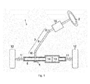
- FIG. 1 in a vehicle steering system 1, a pinion (not shown) provided in a steering shaft 3 to which a steering wheel 2 is fixed meshes with a rack shaft 5 through a rack-and-pinion mechanism 4.
- rotation of the steering shaft 3 in association with a steering operation is converted into a linear reciprocating motion of the rack shaft 5 by the rack-and-pinion mechanism 4.
- the steering shaft 3 is formed by connecting a column shaft 8, an intermediate shaft 9, and a pinion shaft 10.
- a linear reciprocating motion of the rack shaft 5 in association with rotation of the steering shaft 3 is transmitted to knuckles (not shown) through tie rods 11 connected to respective ends of the rack shaft 5.
- the vehicle steering system 1 is configured as a so-called "rack assist type electric power steering system", in which rotation of a motor 13 is converted to a reciprocating motion of the rack shaft 5 by a ball screw mechanism 14 and thus transmitted so that the motor toque is applied to a steering system as an assist force.
- a transmission ratio variable device 15 is provided in an intermediate portion of the column shaft 8.
- the transmission ratio variable device 15 changes a ratio of a rudder angle (a tire angle) of the steered wheels 12 to a rudder angle (a steering angle) of the steering wheel 2, in other words, a transmission ratio (a steering gear ratio).
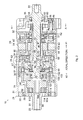
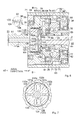
- the transmission ratio variable device 15 includes a substantially cylindrical housing 21 fixed to a vehicle body (not shown) of a vehicle, a first shaft 22 that serves as an input shaft to which rotation in association with a steering operation is input, and a second shaft 23 that serves as an output shaft connected to the intermediate shaft 9 (see FIG. 1 ).
- the first shaft 22 and the second shaft 23 are supported so as to rotate with respect to the housing 21, and constitute the foregoing column shaft 8.
- the transmission ratio variable device 15 includes a motor 24 housed in the housing 21, and a nutation gear mechanism 25 that serves as a differential mechanism.
- the transmission ratio variable device 15 adds motor-driven rotation to rotation of the first shaft 22 by using the nutation gear mechanism 25 and transmits resultant rotation to the second shaft 23.
- the transmission ratio variable device 15 also includes a lock mechanism 26 that is able to mechanically fix a transmission ratio by locking (restraining) rotation of the motor 24 as necessary.
- the housing 21 includes a cylindrical housing body 31 in which the motor 24 and the nutation gear mechanism 25 are housed, an annular upper cover 32 that covers one axial end side (a right side in FIG. 2 : a side indicated by an arrow al (an arrow al-side)) of the housing body 31, and an annular lower cover 33 that covers the other axial end side (a left side in FIG. 2 : a side indicated by an arrow a2 (an arrow a2-side)) of the housing body 31.
- an annular partition wall portion 34 which extends toward a radially inner side, is formed.
- the housing 21 includes a bottomed cylindrical lock case 37 that is fixed to the arrow al-side of the upper cover 32.
- the lock mechanism 26 is housed in the lock case 37.
- the first shaft 22 is supported by a bearing 38 that is provided in a bottom portion of the lock case 37 so that the first shaft 22 is rotatable.
- the second shaft 23 is supported by a bearing 39 that is provided in the lower cover 33 so that the second shaft 23 is rotatable.
- the first shaft 22 and the second shaft 23 are arranged coaxially with each other.
- the motor 24 is configured as a brushless motor that includes a stator 41 fixed within the motor chamber 35, and a rotor 42 provided inside the stator 41 so that the rotor 42 is rotatable.
- the stator 41 has a stator core 43 that is formed in an annular shape, and coils 44 wound around teeth 43a of the stator core 43.
- the rotor 42 has an annular rotor core 46 fixed to an outer periphery of a motor shaft 45, and a permanent magnet 47 fixed to an outer periphery of the rotor core 46.
- the motor shaft 45 is formed in a hollow shape, and the first shaft 22 is fitted and inserted into the motor shaft 45 so as to be coaxial with the motor shaft 45.
- An axial length of the motor shaft 45 is set so as to be larger than an axial length of the motor chamber 35.
- An axial end portion of the motor shaft 45 on the arrow al-side is arranged in the lock case 37, and an axial end portion of the motor shaft 45 on the arrow a2-side is arranged in the gear chamber 36.
- the motor shaft 45 is supported by a bearing 49 provided in the upper cover 32, and by a bearing 48 provided in the partition wall portion 34 so that the motor shaft 45 is rotatable.
- a recessed housing portion 51 which is recessed toward the motor chamber 35-side, is formed in a center of the upper cover 32, and, a rotation angle sensor 52 (for example, a resolver) that detects a rotation angle of the rotor 42 is housed in the recessed housing portion 51.
- a rotation angle sensor 52 for example, a resolver
- an inclined shaft 53 is connected to the axial end portion of the motor shaft 45 on the arrow a2-side so that the inclined shaft 53 is rotatable together with the motor shaft 45.
- the inclined shaft 53 is provided with an inclined support portion 55 that has a shaft center L2 inclined with respect to a shaft center L1 of the motor shaft 45 (the shaft center of the first shaft 22 and the second shaft 23).
- An outer periphery of the inclined support portion 55 is formed in a cylindrical shape that is inclined with respect to the shaft center L1.
- a bearing 56 is disposed between the inclined shaft 53 and the first shaft 22.
- the nutation gear mechanism 25 includes a first gear 61 that is connected to the first shaft 22 so as to be rotatable together with the first shaft 22, a fourth gear 62 that is connected to the second shaft 23 so as to be rotatable together with the second shaft 23, and a nutation gear 63 that is arranged between the first gear 61 and the fourth gear 62 and connected to the motor shaft 45 through the inclined shaft 53.
- the first gear 61 is formed in a disc shape. On an outer peripheral edge of the first gear 61, a plurality of first teeth 64 projecting toward the arrow al-side are arranged in a circumferential direction. In this embodiment, each of the first teeth 64 is arranged radially with respect to the first gear 61, and is constituted by a roller that is provided so as to be rotatable about an axis thereof. A through hole 65, which extends through the first gear 61 in an axial direction, is formed at a center of the first gear 61. As an axial end portion of the first shaft 22 is press-fitted into the through hole 65, the first gear 61 is coaxially connected to the first shaft 22 so as to be rotatable together with the first shaft 22. In other words, a shaft center of the first gear 61 coincides with a shaft center of the motor shaft 45.
- the fourth gear 62 is formed in an annular shape.
- a plurality of fourth teeth 66 projecting toward the arrow a2-side are arranged in the circumferential direction.
- each of the fourth teeth 66 arranged radially with respect to the fourth gear 62 and is constituted by a roller that is provided so as to be rotatable about an axis thereof.
- the fourth gear 62 is fixed to an inner periphery of a connecting cylinder 67 that is formed in a cylindrical shape, and the fourth gear 62 is connected to the second shaft 23 through the connecting cylinder 67.
- the connecting cylinder 67 is supported by a bearing 68 that is provided adjacent to the arrow a2-side of the partition wall portion 34 so that the connecting cylinder 67 is rotatable, and the connecting cylinder 67 is coaxially connected to the second shaft 23 so as to be rotatable together with the second shaft 23.
- the fourth gear 62 is coaxially connected to the second shaft 23 through the connecting cylinder 67 so that the fourth gear 62 is rotatable together with second shaft 23, and the shaft center of the fourth gear 62 coincides with the shaft center L1 of the motor shaft 45.
- Bearings 69 and 70 are provided between the connecting cylinder 67 and the first gear 61, and between the inclined shaft 53 and the fourth gear 62, respectively.
- the nutation gear 63 includes a cylindrical inner ring 71, a cylindrical outer ring gear 72, and balls 73 provided between the inner ring 71 and the outer ring gear 72.
- a plurality of second teeth 74, which are able to mesh with the first teeth 64, are arranged in the circumferential direction on an arrow a2-side end face (a first gear 61-side end face) of the outer ring gear 72.
- a plurality of third teeth 75 which are able to mesh with the fourth teeth 66, are arranged in the circumferential direction on an arrow al -side end face (a fourth gear 62-side end face) of the outer ring gear 72.
- second and third gears 76 and 77 are constituted by the outer ring gear 72.
- the number of the second teeth 74 is set to be smaller by one than the number of the first teeth 64, and the number of the third teeth 75 is set to be equal to the number of the fourth teeth 66.
- the inner ring 71 is connected to an outer periphery of the inclined support portion 55 by a fixing member 78 that is fixed to an arrow a2-side end portion of the inclined shaft 53 so that the inner ring 71 is rotatable together with the inclined shaft 53 (the motor shaft 45).
- a shaft center of the nutation gear 63 coincides with the shaft center L2 of the inclined support portion 55, and the nutation gear 63 rotates about an axis inclined with respect to the axis of the first and fourth gears 61 and 62.
- a rotation difference between the first gear 61 and the second gear 76, and the fourth gear 62 and the third gear 77 based on a difference in the number of teeth is added to the rotation of the first shaft 22 as motor-driven rotation, and resultant rotation is transmitted to the second shaft 23.
- a rotation transmission ratio between the first shaft 22 and the second shaft 23, that is, a transmission ratio between the steering wheel 2 and the steered wheels 12, is changed in accordance with the motor-driven rotation.
- the lock mechanism 26 includes a lock holder 82 provided around the motor shaft 45 through a tolerance ring 81 so as to be rotatable together with the motor shaft 45, a lock arm 83 that is able to restrain rotation of the lock holder 82, and a solenoid 84 that drives the lock arm 83.
- the lock holder 82 is formed in a substantially annular shape, and fixed to an axial end portion of the motor shaft 45.
- a plurality of (in this embodiment, four) engaging grooves 85 are formed in an outer periphery of the lock holder 82.
- the engaging grooves 85 are open toward both sides of the lock holder 82 in a thickness direction (the axial direction), and extend in the circumferential direction.
- the engaging grooves 85 are formed at four locations in the outer periphery of the lock holder 82 at equal angular intervals (of 90 degrees).
- the lock arm 83 is supported with respect to a support shaft 86 that is arranged radially outside the lock holder 82 so that the lock arm 83 is able to pivot about a shaft center of the support shaft 86.
- An engaging lug 87 which projects toward the outer periphery of the lock holder 82, is provided in one end of the lock arm 83.
- a shaft-shaped plunger 88 is connected to the other end of the lock arm 83, and is configured so as to be able to move forward and backward along an axial direction of the plunger 88 as the solenoid 84 is driven.
- the support shaft 86 and the solenoid 84 are fixed to the housing 21 (see FIG. 2 ).
- the lock arm 83 is urged by an elastic force of a torsion coil spring 89 fitted to a periphery of the support shaft 86 so that an engaging lug 87-side end portion of the lock arm 83 pivots toward the lock holder 82-side.
- the lock arm 83 restrains rotation of the motor shaft 45 when the engaging lug 87 is inserted in the engaging groove 85 and engaged with the engaging groove 85 in the circumferential direction.
- the tolerance ring 81 is formed by bending a belt-shaped metallic plate into a substantially C shape, and has a plurality of spring portions 81a projecting toward a radially outer side.
- the tolerance ring 81 restricts relative rotation between the motor shaft 45 and lock holder 82 based on friction resistance between an outer periphery (the spring portions 81a) of the tolerance ring 81 and the lock holder 82.
- the outer periphery of the tolerance ring 81 serves as a sliding surface.
- the tolerance ring 81 rotates relative to the lock holder 82, the tolerance ring 81 allows relative rotation between the motor shaft 45 and the lock holder 82, in other words, the tolerance ring 81 functions as a torque limiter.
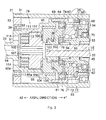
- the preload applying mechanism 79 is configured so as to be able to adjust and maintain an axial preload applied from outside to the nutation gear mechanism 25 in a state where the transmission ratio variable device 15 is assembled.
- the second shaft 23 includes a shaft portion 91 having a shaft shape and projecting outside the housing 21, a bottomed cylindrical housing portion 92 provided on the arrow al-side of the shaft portion 91, and a cylindrical portion 93 that is provided on the arrow al-side of the housing portion 92, and has a cylindrical shape with an outside diameter larger than an outside diameter of the housing portion 92.
- a communicating hole 94 is formed so as to extend through the shaft portion 91 in the axial direction.
- An outside and an inside of the housing portion 92 communicate with each other through the communicating hole 94.
- an internal thread portion 95 is formed in an inner periphery of the housing portion 92.
- the internal thread portion 95 includes a small-diameter internal thread portion 95a provided on a shaft portion 91-side, and a large-diameter internal thread portion 95b that is provided on the arrow al-side of the shaft portion 91 and set so that an inside diameter of a thread ridge is larger than an inside diameter of a thread ridge of the small-diameter internal thread portion 95a.
- the connecting cylinder 67 is connected to an arrow al-side end portion of the cylindrical portion 93 so that the connecting cylinder 67 is rotatable together with the cylindrical portion 93.
- the preload applying mechanism 79 includes a preload adjusting plug 101 that is screwed to the large-diameter internal thread portion 95b and arranged inside the housing portion 92, an annular raceway collar 103 that holds a thrust needle 102 serving as a bearing between the raceway collar 103 and the first gear 61 so that the thrust needle 102 is able to roll, and a wave washer 104 that serves as an elastic member and that is arranged between the preload adjusting plug 101 and the raceway collar 103.
- the wave washer 104 is compressed by a given amount between the preload adjusting plug 141 and the raceway collar 103, and applies a given preload to the nutation gear mechanism 25 by pressing the first gear 61 to the fourth gear 62-side by using an elastic force of the wave washer 104.
- preload applying means is constituted by the preload adjusting plug 101 and the wave washer 104.
- the raceway collar 103 and the thrust needle 102 are arranged inside the cylindrical portion 93, and a bush 105 is provided between the raceway collar 103 and the cylindrical portion 93.
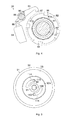
- the preload adjusting plug 101 is formed in a disc shape, and an external thread portion 106, which meshes with the large-diameter internal thread portion 95b, is formed on an outer periphery of the preload adjusting plug 101.
- a protrusion 107 projecting toward the arrow a2-side is formed at a location that faces the communicating hole 94.
- an operation hole 108 is formed so as to extend through the preload adjusting plug 101 in the axial direction, at a position facing the communicating hole 94.
- the operation hole 108 has a shape (for example, a hexagonal shape) that allows the preload adjusting plug 101 to rotate when a tool (not shown) is engaged with the operation hole 108 in the circumferential direction.
- the preload adjusting plug 101 is able to be operated (screwed forward and backward) from outside through the communicating hole 94.
- the preload applying mechanism 79 also includes a lock nut 111 that serves as locking means, and that is screwed to the small-diameter internal thread portion 95a.
- the lock nut 111 is formed in an annular shape and arranged on an outer periphery of the protrusion 107.
- an external thread portion 112 which is screwed to the small-diameter internal thread portion 95a, is formed.
- the lock nut 111 is screwed to the small-diameter internal thread portion 95a so as to press the preload adjusting plug 101 toward the arrow al-side (toward the nutation gear mechanism 25).
- the external thread portion 106 of the preload adjusting plug 101 and the large-diameter internal thread portion 95b are in close contact with each other. This restricts loosening of the preload adjusting plug 101 (restricts the preload adjusting plug 101 from rotating so as to move toward the arrow a2-side).
- a plurality of operation holes 113 are formed at equal angular intervals in the circumferential direction and extend through the lock nut 111 in the axial direction.
- a plurality of through holes 114 which extend through the bottom portion 92a of the housing portion 92 in the axial direction, are formed at positions that face the operation holes 113.
- Each of the through holes 114 is formed in an arc shape extending over a given circumferential range.
- preload adjustment operation (action) of the preload applying mechanism After assembling the transmission ratio variable device 15, an operator inserts a tool into the operation hole 108 of the preload adjusting plug 101 from outside through the communicating hole 94 of the shaft portion 91, and rotates (operates) the preload adjusting plug 101 with given fastening toque that is previously determined based on experiments and the like. Thus, the preload adjusting plug 101 is moved to a position such that the wave washer 104 is compressed by a given amount between the preload adjusting plug 101 and the raceway collar 103 regardless of an assembly error and the like, and a given preload is applied to the nutation gear mechanism 25.
- the operator inserts a tool into the operation holes 113 of the lock nut 111 through the through holes 114, and rotates the lock nut 111 so that the lock nut 111 presses the preload adjusting plug 101 toward the nutation gear mechanism 25. Accordingly, the external thread portion 106 and the large-diameter internal thread portion 95b (the internal thread portion 95) are in close contact with each other, and thus, loosening of the preload adjusting plug 101 is restricted.
- the axial preload applied to the nutation gear mechanism 25 is adjustable in a state where the transmission ratio variable device 15 is assembled. Therefore, variation in the preload applied to the nutation gear mechanism 25 is reduced even when there are an assembly error and the like.
- the axial preload is applied to the nutation gear mechanism 25 by using the elastic force of the wave washer 104. Therefore, a change in the preload due to a change of the position of the preload adjusting plug 101 is small as compared to a case where a preload is directly applied by the preload adjusting plug 101. This lowers a required level of positional accuracy of the preload adjusting plug 101, thereby making it easier to adjust the preload applied to the nutation gear mechanism 25. Also, the wave washer 104 is able to absorb vibration that occurs in the nutation gear mechanism 25, thereby preventing occurrence of noise.
- the preload adjusting plug 101 is screwed to the second shaft 23.
- the preload applying mechanism 79 is configured so as to restrict loosening of the preload adjusting plug 101, the preload adjusting plug 101 is not loosened due to vibration and the like while in use, an adjusted preload is maintained, and a good meshing state of the nutation gear mechanism 25 is maintained.
- annular flange portion 121 that extends toward a radially outer side is formed in an arrow al-side end portion of a housing portion 92, and a connecting cylinder 67 is connected to the flange portion 121.
- An internal thread portion 95 according to this embodiment is formed such that an inside diameter thereof is substantially uniform over the entire internal thread portion 95 in the axial direction.
- an engaging hole 123 is formed in a center of a preload adjusting plug 101.
- the engaging hole 123 is open toward the arrow a2-side, and an internal spline 122 is formed in an inner periphery of the engaging hole 123.
- a press-fitting hole 124 is formed in the preload adjusting plug 101.
- the press-fitting hole 124 axially extends through the preload adjusting plug 101 and is open to a bottom surface of the engaging hole 123.
- the press-fitting hole 124 is formed in a tapered shape such that an inside diameter of the press-fitting hole 124 is gradually reduced toward the arrow al-side from the arrow a2-side.
- a wave washer 104 is compressed by a given amount between the preload adjusting plug 101 and a raceway collar 103 similarly to the foregoing first embodiment, and applies a given preload to a nutation gear mechanism 25 by using an elastic force of the wave washer 104.
- a preload applying mechanism 79 includes a press-fitting member 125 that is press-fitted into the press-fitting hole 124 so as to deform the preload adjusting plug 101 so that a diameter of the preload adjusting plug 101 is increased. More specifically, the press-fitting member 125 has a fitting portion 127 in which an external spline 126 corresponding to the internal spline 122 is formed, and a press-fitting portion 128 that projects from the fitting portion 127 toward the arrow al-side and is inserted into the press-fitting hole 124.
- the press-fitting member 125 is rotatable together with the preload adjusting plug 101 and movable in an axial direction with respect to the preload adjusting plug 101.
- the press-fitting portion 128 is formed. in a tapered shape such that an outside diameter of the press-fitting portion 128 is gradually reduced toward the arrow al-side from the arrow a2-side.
- a maximum outside diameter of the press-fitting portion 128 (an outside diameter of an arrow a2-side end portion of the press-fitting portion 128) is set to be larger than a maximum inside diameter of the press-fitting hole 124 (an inside diameter of an arrow a2-side end portion of the press-fitting hole 124).
- an operation hole 129 which is open toward the arrow a2-side, is formed at a position facing a communicating hole 94.
- the operation hole 129 is formed in a shape that allows the preload adjusting plug 101 to rotate when a tool (not shown) is engaged with the operation hole 129 in the circumferential direction, and that allows the press-fitting member 125 to be pressed toward the arrow al-side.
- a plurality of pairs of elongated holes 131a and 131b are provided at equal angular intervals in the circumferential direction.
- the elongated holes 131a and 131b in each pair extend substantially along a radial direction, and are arranged to be parallel to each other. Therefore, in the preload adjusting plug 101, bridge portions 132a on both sides of each elongated hole 131a in a longitudinal direction thereof and bridge portions 132b on both sides of each elongated hole 131b in a longitudinal direction thereof have lower mechanical strength than other parts so as to be deformed easily in the radial direction.
- a diameter of the preload adjusting plug 101 is increased when parts between the elongated holes 131a and 131b and between the bridge portions 132a and 132b in the preload adjusting plug 101 are mainly displaced radially outwardly as the press-fitting member 125 is press-fitted.
- the bridge portions 132a and 132b correspond to a low-strength portion.
- a soft member 133 is provided on an outer periphery of an external thread portion 106 of the preload adjusting plug 101.
- the soft member 133 has lower mechanical strength than mechanical strength of the preload adjusting plug 101.
- the soft member 133 is provided in a screwed portion between the housing portion 92 of the second shaft 23 and the preload adjusting plug 101.
- the preload adjusting plug 101 is made of a metallic material such as iron
- the soft member 133 is made of a metallic material such as copper.
- locking means is constituted by the press-fitting member 125 and the soft member 133.
- the preload adjusting plug 101 is deformed so that the diameter of the preload adjusting plug 101 is increased, and the small clearance between the external thread portion 106 and the internal thread portion 95 is filled, and thus, loosening of the preload adjusting plug 101 is restricted.
- the elongated holes 131a and 131b are formed in the preload adjusting plug 101.
- the bridge portions 132a with low mechanical strength are provided on both sides of each elonagted hole 131a in the longitudinal direction, and the bridge portions 132b with low mechanical strength are provided on both sides of each elonagted hole 131b in the longitudinal direction. Therefore, the preload adjusting plug 101 is deformed easily.
- the soft member 133 is provided in the screwed portion between the housing portion 92 and the preload adjusting plug 101. Therefore, the small clearance between the external thread portion 106 and the internal thread portion 95 is filled securely by the soft member 133. Thus, it is possible to more reliably restrict loosening of the preload adjusting plug 101.
- an annular flange portion 141 that extends toward a radially outer side is formed in an arrow al-side end portion of a housing portion 92, and a connecting cylinder 67 is connected to the flange portion 141.
- An internal thread portion 95 according to this embodiment is fonned such that an inside diameter thereof is substantially uniform over the entire internal thread portion 95 in the axial direction.
- a groove-shaped engaging recessed portion 142 is formed in the housing portion 92. The engaging recessed portion 142 extends in the axial direction and is open toward the arrow al-side.
- a preload applying mechanism 79 includes a friction plate 143 arranged between a preload adjusting plug 101 and a wave washer 104.
- the wave washer 104 is compressed by a given amount between the friction plate 143 and a raceway collar 103, and applies a given preload to a nutation gear mechanism 25 by using an elastic force of the wave washer 104.
- the friction plate 143 is formed in a disc shape.
- On an outer periphery of the friction plate 143 an engaging projecting portion 144 is formed. The engaging projecting portion 144 projects to a radially outer side and is inserted in the engaging recessed portion 142.
- the friction plate 143 is restricted from rotating relative to a second shaft 23.
- a contact surface 143a of the friction plate 143 which contacts the preload adjusting plug 101, has been subjected to a high ⁇ process for increasing the friction coefficient ⁇ of the contact surface 143a.
- small projections and recesses are formed on the contact surface 143a by knurling, and the coefficient of friction of the contact surface 143a is thus increased.
- locking means is constituted by the friction plate 143.
- a preload adjustment operation (action) according to this embodiment will be described.
- an operator inserts a tool into an operation hole 129 of the preload adjusting plug 101 from outside through a communicating hole 94 of a shaft portion 91, and rotates the preload adjusting plug 101 with given tightening torque.
- the wave washer 104 is compressed by a given amount, and a given preload is applied to the nutation gear mechanism 25, and in addition, the preload adjusting plug 101 and the friction plate 143 are frictionally engaged with each other.
- the given tightening torque is set to be larger than the given tightening torque in the foregoing first embodiment.
- the following effect is obtained in addition to the effects (1) to (3) of the foregoing first embodiment. (7) Since the contact surface 143a of the friction plate 143 has been subjected to the high ⁇ process for increasing the friction coefficient ⁇ of the contact surface 143a, a frictional force that acts between the preload adjusting plug 101 and the friction plate 143 is increased. Therefore, it is possible to more reliably restrict loosening of the preload adjusting plug 101.
- annular flange portion 151 that extends toward a radially outer side is formed in an arrow al-side end portion of a housing portion 92, and a connecting cylinder 67 is connected to the flange portion 151.
- An internal thread portion 152 is formed in an inner periphery of a shaft portion 91. There is no internal thread portion formed in the inner periphery of the housing portion 92 according to this embodiment.
- a preload applying mechanism 79 does not include an elastic member such as a wave washer.
- the preload applying mechanism 79 applies a preload to a nutation gear mechanism 25 as a preload adjusting plug 101 directly presses a first gear 61 through a thrust needle 102.
- a raceway portion 153 is formed in the preload adjusting plug 101.
- the raceway portion 153 extends toward a radially outer side from an arrow al-side end portion of the preload adjusting plug 101, and retains the thrust needle 102 so that the thrust needle 102 is able to roll.
- a projecting portion 154 is formed in the preload adjusting plug 101.
- the projecting portion 154 projects from a center of the preload adjusting plug 101 to the arrow a2-side, and is inserted in a communicating hole 94 of the shaft portion 91.
- the projecting portion 154 is formed in a shaft shape.
- an external thread portion 155 which is screwed to the internal thread portion 152, is formed.
- an operation hole 156 which is open toward the arrow a2-side, is formed.
- the operation hole 156 has a shape that allows the preload adjusting plug 101 to rotate when a tool (not shown) is engaged with the operation hole 156 in the circumferential direction.
- preload applying means is constituted by the preload adjusting plug 101.
- a swaged portion 157 is formed by swaging the shaft portion 91 so that a diameter of the shaft portion 91 is reduced. Therefore, a small clearance between the external thread portion 155 and a position in the internal thread portion 152 corresponding to the swaged portion 157 is filled, and loosening of the preload adjusting plug 101 is thus restricted.
- locking means is constituted by the swaged portion 157.
- Loosening of the preload adjusting plug 101 is restricted because the swaged portion 157 is formed in the part of the shaft portion 91, to which the projecting portion 154 is screwed. Therefore, loosening of the preload adjusting plug 101 is restricted with a simple structure without adding a component separately.
- the internal thread portion 95 is constituted by the small-diameter internal thread portion 95a and the large-diameter internal thread portion 95b.
- an inside diameter of the internal thread portion 95 may be substantially uniform over the entire internal thread portion 95 in the axial direction.
- the soft member 133 is formed of a metallic material such as copper.
- the present invention is not limited to this, and the soft member 133 may be formed of another material such as resin or rubber as long as the soft member 133 has lower mechanical strength than mechanical strength of the preload adjusting plug 101.
- the soft member 133 may not be provided between the external thread portion 106 and the internal thread portion 95.
- the elongated holes 131a and 131b are formed in the preload adjusting plug 101, and thus, the bridge portions 132a with low mechanical strength are formed on both sides of each elonagated hole 131a in the longitudinal direction and the bridge portions 132b with low mechanical strength are formed on both sides of each elongated hole 131b in the longitudinal direction.
- the present invention is not limited to this, low-strength portions with low mechanical strength may be formed in the preload adjusting plug 101 by forming circular holes or grooves other than the elongated holes 131a and 131b.
- the elongated holes 131a and 131b may not be formed in the preload adjusting plug 101, and the low-strength portion may not be provided.
- the press-fitting hole 124 and the press-fitting portion 128 are formed in tapered shapes.
- the present invention is not limited to this, and the shapes of the press-fitting hole 124 and the press-fitting portion 128 may be changed as appropriate as long as the diameter of the preload adjusting plug 101 is increased by pressing the press-fitting portion 128 into the press-fitting hole 124.
- knurling is used as the high ⁇ process for increasing the friction coefficient ⁇ performed on the contact surface 143a of the friction plate 143.
- the present invention is not limited to this, and other machining methods such as graining may be used.
- plating may be used to cover the contact surface 143a with a material having a high friction coefficient.
- the high ⁇ process for increasing the friction coefficient ⁇ is performed on the contact surface 143a of the friction plate 143.
- the present invention is not limited to this, and the high ⁇ process for increasing the friction coefficient ⁇ may be performed only on a contact surface 101a (see FIG. 8 ) of the preload adjusting plug 101, which contacts the friction plate 143, or on both of the contact surfaces 101a and 143a.
- the high ⁇ process for increasing the friction coefficient ⁇ may not be performed on the contact surfaces 101a and 143a.
- the engaging projecting portion 144 is formed in the friction plate 143, and rotation of the friction plate 143 with respect to the second shaft 23 is restricted as the engaging projecting portion 144 is engaged with the engaging recessed portion 142 of the housing portion 92.
- the present invention is not limited to this.
- an engaging recessed portion 161 may be formed on an outer periphery of the friction plate 143, and, an engaging member 162, which is engaged with both the engaging recessed portions 142 and 161, may be fixed to the housing portion 92 so as to restrict the rotation of the friction plate 143 with respect to the second shaft 23.
- the wave washer 104 may not be provided, and the preload adjusting plug 101 may directly press the first gear 61 through the thrust needle 102a so as to apply a preload to the nutation gear mechanism 25.
- a wave washer, a raceway collar, and a thrust needle may be provided between the preload adjusting plug 101 and the first gear 61, and a preload may be applied to the nutation gear mechanism 25 by an elastic force of the wave washer.
- the wave washer 104 is used as the elastic member.
- the present invention is not limited to this, and a spring member such as a disc spring, or an elastic body such as rubber may be used.
- the preload applying mechanism 79 may not include the lock nut 111, that is, locking means, which restricts loosening of the preload adjusting plug 101, and thus may not be configured to restrict loosening of the preload adjusting plug 101.
- the preload applying mechanism 79 may not include the locking means, and thus may not be configured to restrict loosening of the preload adjusting plug 101.
- the steering wheel 2 may be connected to the second shaft 23-side, and the intermediate shaft 9 may be connected to the first shaft 22-side.
- the first shaft 22 may serve as an output shaft
- the second shaft 23 may serve as an input shaft.
- the present invention is applied to the transmission ratio variable device 15 of a type in which the housing 21 is not rotated by rotation of the first shaft 22 (an input shaft).
- the present invention is not limited to this, and may be applied to a transmission ratio variable device of a type in which a housing is rotated together with an input shaft.
- the present invention is applied to the transmission ratio variable device 15 for the vehicle steering system 1, but may also be applied to transmission ratio variable devices used for other purposes.
Landscapes
- Engineering & Computer Science (AREA)
- General Engineering & Computer Science (AREA)
- Mechanical Engineering (AREA)
- Chemical & Material Sciences (AREA)
- Combustion & Propulsion (AREA)
- Transportation (AREA)
- Power Steering Mechanism (AREA)
- Retarders (AREA)
- General Details Of Gearings (AREA)
Applications Claiming Priority (1)
| Application Number | Priority Date | Filing Date | Title |
|---|---|---|---|
| JP2012176001A JP2014035016A (ja) | 2012-08-08 | 2012-08-08 | 伝達比可変装置 |
Publications (2)
| Publication Number | Publication Date |
|---|---|
| EP2728221A2 true EP2728221A2 (de) | 2014-05-07 |
| EP2728221A3 EP2728221A3 (de) | 2015-07-08 |
Family
ID=48998407
Family Applications (1)
| Application Number | Title | Priority Date | Filing Date |
|---|---|---|---|
| EP13179335.8A Withdrawn EP2728221A3 (de) | 2012-08-08 | 2013-08-06 | Vorrichtung mit variablem Übersetzungsverhältnis |
Country Status (4)
| Country | Link |
|---|---|
| US (1) | US8784253B2 (de) |
| EP (1) | EP2728221A3 (de) |
| JP (1) | JP2014035016A (de) |
| CN (1) | CN103569195A (de) |
Families Citing this family (8)
| Publication number | Priority date | Publication date | Assignee | Title |
|---|---|---|---|---|
| JP2014098469A (ja) * | 2012-11-16 | 2014-05-29 | Jtekt Corp | 伝達比可変装置 |
| CN104097681B (zh) * | 2014-07-29 | 2016-04-06 | 吉林大学 | 采用摆线针轮机构的汽车主动转向系统 |
| DE102015217045A1 (de) * | 2015-09-07 | 2017-03-09 | Volkswagen Aktiengesellschaft | Nutzfahrzeuglenkung |
| CN108268015A (zh) * | 2018-01-24 | 2018-07-10 | 西安康控科尼电子科技有限公司 | 电镀金刚线伺服系统的控制方法 |
| JP7172140B2 (ja) * | 2018-05-30 | 2022-11-16 | 株式会社デンソー | 回転検出装置、および、これを用いた電動パワーステアリング装置 |
| US20200208729A1 (en) | 2018-12-27 | 2020-07-02 | Jtekt Corporation | Gear unit |
| CN111291491B (zh) * | 2020-02-19 | 2023-03-24 | 中南大学 | 面齿轮同轴分扭传动系统振动特性分析方法及系统 |
| JP7472758B2 (ja) * | 2020-11-02 | 2024-04-23 | トヨタ自動車株式会社 | 歯車機構、及び歯車 |
Citations (1)
| Publication number | Priority date | Publication date | Assignee | Title |
|---|---|---|---|---|
| US20080251311A1 (en) | 2005-10-06 | 2008-10-16 | Gerhard Waibel | Superimposed Steering System Comprising a Mechanical Return Level |
Family Cites Families (10)
| Publication number | Priority date | Publication date | Assignee | Title |
|---|---|---|---|---|
| DE3811074A1 (de) * | 1988-03-31 | 1989-10-12 | Teves Gmbh Co Ohg Alfred | Getriebe zum uebertragen einer drehbewegung |
| JP4524595B2 (ja) * | 2004-09-16 | 2010-08-18 | 株式会社ジェイテクト | 舵角比可変操舵装置 |
| JP4241572B2 (ja) * | 2004-10-25 | 2009-03-18 | トヨタ自動車株式会社 | 車輌用電動式パワーステアリング装置 |
| DE102004052562B3 (de) * | 2004-10-29 | 2006-02-09 | Thyssen Krupp Automotive Ag | Kraftfahrzeuglenkung mit Überlagerungsgetriebe |
| EP2202131B1 (de) * | 2007-10-22 | 2013-01-02 | JTEKT Corporation | Mechanismus mit variablem übersetzungsverhältnis und lenkvorrichtung für damit versehenes fahrzeug |
| JP5234314B2 (ja) * | 2007-10-22 | 2013-07-10 | 株式会社ジェイテクト | 車両用操舵装置 |
| JP5282938B2 (ja) * | 2008-07-07 | 2013-09-04 | 株式会社ジェイテクト | 伝達比可変機構およびこれを備える車両用操舵装置 |
| JP5224109B2 (ja) * | 2008-08-27 | 2013-07-03 | 株式会社ジェイテクト | 車両用操舵装置 |
| JP5433238B2 (ja) * | 2009-01-13 | 2014-03-05 | 株式会社ジェイテクト | 歯車装置および揺動歯車装置 |
| JP5472686B2 (ja) * | 2009-05-28 | 2014-04-16 | 株式会社ジェイテクト | 車両用操舵装置 |
-
2012
- 2012-08-08 JP JP2012176001A patent/JP2014035016A/ja active Pending
-
2013
- 2013-07-31 CN CN201310328816.2A patent/CN103569195A/zh active Pending
- 2013-07-31 US US13/955,602 patent/US8784253B2/en not_active Expired - Fee Related
- 2013-08-06 EP EP13179335.8A patent/EP2728221A3/de not_active Withdrawn
Patent Citations (1)
| Publication number | Priority date | Publication date | Assignee | Title |
|---|---|---|---|---|
| US20080251311A1 (en) | 2005-10-06 | 2008-10-16 | Gerhard Waibel | Superimposed Steering System Comprising a Mechanical Return Level |
Also Published As
| Publication number | Publication date |
|---|---|
| US8784253B2 (en) | 2014-07-22 |
| CN103569195A (zh) | 2014-02-12 |
| JP2014035016A (ja) | 2014-02-24 |
| US20140045636A1 (en) | 2014-02-13 |
| EP2728221A3 (de) | 2015-07-08 |
Similar Documents
| Publication | Publication Date | Title |
|---|---|---|
| US8784253B2 (en) | Transmission ratio variable device | |
| EP2597014B1 (de) | Elektrisches Servolenksystem | |
| US9109632B2 (en) | Torque limiter, variable transmission ratio device, and tolerance ring | |
| US8181734B2 (en) | Motor vehicle steering system | |
| EP3424798B1 (de) | Lenksystem und verfahren zur herstellung eines lenksystems | |
| EP1714851B1 (de) | Elektrische servolenkvorrichtung | |
| US8381867B2 (en) | Transmission ratio variable mechanism and vehicle steering apparatus including the same | |
| US8371977B2 (en) | Transmission ratio variable mechanism and motor vehicle steering system including the same | |
| EP2669145B1 (de) | Zahnstangenträgervorrichtung und Lenksystem mit einer Zahnstangenträgervorrichtung | |
| CN116438105B (zh) | 齿轮与旋转轴的组装体及其组装方法 | |
| JP2003014055A (ja) | ウォーム減速装置のバックラッシュ調整装置 | |
| US20240294207A1 (en) | Steering device | |
| EP2657105B1 (de) | Elektrische servolenkvorrichtung | |
| US10906579B2 (en) | Power steering apparatus | |
| EP1813507B1 (de) | Elektrische Servolenkung | |
| KR100262425B1 (ko) | 파워스티어링 장치 | |
| JP2013082348A (ja) | 電動パワーステアリング装置及びその製造方法 | |
| JP2016120729A (ja) | 電動アシスト装置及びその製造方法 | |
| KR20160044771A (ko) | 전동식 파워 스티어링 | |
| JP2006082610A (ja) | 電動パワーステアリング装置 | |
| KR20130014089A (ko) | Eps 모터 | |
| JP2005207447A (ja) | ボールねじ | |
| JP5133736B2 (ja) | パワーステアリング装置 | |
| JP2003028181A (ja) | 継手及びそれを用いた操舵補助装置 | |
| JP2010188876A (ja) | 可変式ステアリング機構及び舵角可変式ステアリング装置 |
Legal Events
| Date | Code | Title | Description |
|---|---|---|---|
| PUAI | Public reference made under article 153(3) epc to a published international application that has entered the european phase |
Free format text: ORIGINAL CODE: 0009012 |
|
| 17P | Request for examination filed |
Effective date: 20130806 |
|
| AK | Designated contracting states |
Kind code of ref document: A2 Designated state(s): AL AT BE BG CH CY CZ DE DK EE ES FI FR GB GR HR HU IE IS IT LI LT LU LV MC MK MT NL NO PL PT RO RS SE SI SK SM TR |
|
| AX | Request for extension of the european patent |
Extension state: BA ME |
|
| PUAL | Search report despatched |
Free format text: ORIGINAL CODE: 0009013 |
|
| AK | Designated contracting states |
Kind code of ref document: A3 Designated state(s): AL AT BE BG CH CY CZ DE DK EE ES FI FR GB GR HR HU IE IS IT LI LT LU LV MC MK MT NL NO PL PT RO RS SE SI SK SM TR |
|
| AX | Request for extension of the european patent |
Extension state: BA ME |
|
| RIC1 | Information provided on ipc code assigned before grant |
Ipc: B62D 5/04 20060101ALI20150529BHEP Ipc: F16H 1/32 20060101AFI20150529BHEP |
|
| STAA | Information on the status of an ep patent application or granted ep patent |
Free format text: STATUS: THE APPLICATION IS DEEMED TO BE WITHDRAWN |
|
| 18D | Application deemed to be withdrawn |
Effective date: 20160109 |