EP2728242A1 - Système d'accumulation de pression et procédé de fonctionnement d'un système d'accumulation de pression - Google Patents
Système d'accumulation de pression et procédé de fonctionnement d'un système d'accumulation de pression Download PDFInfo
- Publication number
- EP2728242A1 EP2728242A1 EP20120191303 EP12191303A EP2728242A1 EP 2728242 A1 EP2728242 A1 EP 2728242A1 EP 20120191303 EP20120191303 EP 20120191303 EP 12191303 A EP12191303 A EP 12191303A EP 2728242 A1 EP2728242 A1 EP 2728242A1
- Authority
- EP
- European Patent Office
- Prior art keywords
- pressure
- valve
- check valve
- piston
- accumulator
- Prior art date
- Legal status (The legal status is an assumption and is not a legal conclusion. Google has not performed a legal analysis and makes no representation as to the accuracy of the status listed.)
- Granted
Links
Images






Classifications
-
- F—MECHANICAL ENGINEERING; LIGHTING; HEATING; WEAPONS; BLASTING
- F15—FLUID-PRESSURE ACTUATORS; HYDRAULICS OR PNEUMATICS IN GENERAL
- F15B—SYSTEMS ACTING BY MEANS OF FLUIDS IN GENERAL; FLUID-PRESSURE ACTUATORS, e.g. SERVOMOTORS; DETAILS OF FLUID-PRESSURE SYSTEMS, NOT OTHERWISE PROVIDED FOR
- F15B1/00—Installations or systems with accumulators; Supply reservoir or sump assemblies
- F15B1/02—Installations or systems with accumulators
- F15B1/04—Accumulators
-
- F—MECHANICAL ENGINEERING; LIGHTING; HEATING; WEAPONS; BLASTING
- F17—STORING OR DISTRIBUTING GASES OR LIQUIDS
- F17C—VESSELS FOR CONTAINING OR STORING COMPRESSED, LIQUEFIED OR SOLIDIFIED GASES; FIXED-CAPACITY GAS-HOLDERS; FILLING VESSELS WITH, OR DISCHARGING FROM VESSELS, COMPRESSED, LIQUEFIED, OR SOLIDIFIED GASES
- F17C13/00—Details of vessels or of the filling or discharging of vessels
- F17C13/04—Arrangement or mounting of valves
-
- F—MECHANICAL ENGINEERING; LIGHTING; HEATING; WEAPONS; BLASTING
- F17—STORING OR DISTRIBUTING GASES OR LIQUIDS
- F17C—VESSELS FOR CONTAINING OR STORING COMPRESSED, LIQUEFIED OR SOLIDIFIED GASES; FIXED-CAPACITY GAS-HOLDERS; FILLING VESSELS WITH, OR DISCHARGING FROM VESSELS, COMPRESSED, LIQUEFIED, OR SOLIDIFIED GASES
- F17C5/00—Methods or apparatus for filling containers with liquefied, solidified, or compressed gases under pressures
- F17C5/06—Methods or apparatus for filling containers with liquefied, solidified, or compressed gases under pressures for filling with compressed gases
-
- F—MECHANICAL ENGINEERING; LIGHTING; HEATING; WEAPONS; BLASTING
- F17—STORING OR DISTRIBUTING GASES OR LIQUIDS
- F17C—VESSELS FOR CONTAINING OR STORING COMPRESSED, LIQUEFIED OR SOLIDIFIED GASES; FIXED-CAPACITY GAS-HOLDERS; FILLING VESSELS WITH, OR DISCHARGING FROM VESSELS, COMPRESSED, LIQUEFIED, OR SOLIDIFIED GASES
- F17C13/00—Details of vessels or of the filling or discharging of vessels
- F17C13/02—Special adaptations of indicating, measuring, or monitoring equipment
-
- F—MECHANICAL ENGINEERING; LIGHTING; HEATING; WEAPONS; BLASTING
- F17—STORING OR DISTRIBUTING GASES OR LIQUIDS
- F17C—VESSELS FOR CONTAINING OR STORING COMPRESSED, LIQUEFIED OR SOLIDIFIED GASES; FIXED-CAPACITY GAS-HOLDERS; FILLING VESSELS WITH, OR DISCHARGING FROM VESSELS, COMPRESSED, LIQUEFIED, OR SOLIDIFIED GASES
- F17C2205/00—Vessel construction, in particular mounting arrangements, attachments or identifications means
- F17C2205/01—Mounting arrangements
- F17C2205/0123—Mounting arrangements characterised by number of vessels
- F17C2205/013—Two or more vessels
- F17C2205/0134—Two or more vessels characterised by the presence of fluid connection between vessels
-
- F—MECHANICAL ENGINEERING; LIGHTING; HEATING; WEAPONS; BLASTING
- F17—STORING OR DISTRIBUTING GASES OR LIQUIDS
- F17C—VESSELS FOR CONTAINING OR STORING COMPRESSED, LIQUEFIED OR SOLIDIFIED GASES; FIXED-CAPACITY GAS-HOLDERS; FILLING VESSELS WITH, OR DISCHARGING FROM VESSELS, COMPRESSED, LIQUEFIED, OR SOLIDIFIED GASES
- F17C2205/00—Vessel construction, in particular mounting arrangements, attachments or identifications means
- F17C2205/03—Fluid connections, filters, valves, closure means or other attachments
- F17C2205/0302—Fittings, valves, filters, or components in connection with the gas storage device
- F17C2205/0323—Valves
- F17C2205/0335—Check-valves or non-return valves
-
- F—MECHANICAL ENGINEERING; LIGHTING; HEATING; WEAPONS; BLASTING
- F17—STORING OR DISTRIBUTING GASES OR LIQUIDS
- F17C—VESSELS FOR CONTAINING OR STORING COMPRESSED, LIQUEFIED OR SOLIDIFIED GASES; FIXED-CAPACITY GAS-HOLDERS; FILLING VESSELS WITH, OR DISCHARGING FROM VESSELS, COMPRESSED, LIQUEFIED, OR SOLIDIFIED GASES
- F17C2205/00—Vessel construction, in particular mounting arrangements, attachments or identifications means
- F17C2205/03—Fluid connections, filters, valves, closure means or other attachments
- F17C2205/0302—Fittings, valves, filters, or components in connection with the gas storage device
- F17C2205/037—Quick connecting means, e.g. couplings
-
- F—MECHANICAL ENGINEERING; LIGHTING; HEATING; WEAPONS; BLASTING
- F17—STORING OR DISTRIBUTING GASES OR LIQUIDS
- F17C—VESSELS FOR CONTAINING OR STORING COMPRESSED, LIQUEFIED OR SOLIDIFIED GASES; FIXED-CAPACITY GAS-HOLDERS; FILLING VESSELS WITH, OR DISCHARGING FROM VESSELS, COMPRESSED, LIQUEFIED, OR SOLIDIFIED GASES
- F17C2221/00—Handled fluid, in particular type of fluid
- F17C2221/01—Pure fluids
- F17C2221/012—Hydrogen
-
- F—MECHANICAL ENGINEERING; LIGHTING; HEATING; WEAPONS; BLASTING
- F17—STORING OR DISTRIBUTING GASES OR LIQUIDS
- F17C—VESSELS FOR CONTAINING OR STORING COMPRESSED, LIQUEFIED OR SOLIDIFIED GASES; FIXED-CAPACITY GAS-HOLDERS; FILLING VESSELS WITH, OR DISCHARGING FROM VESSELS, COMPRESSED, LIQUEFIED, OR SOLIDIFIED GASES
- F17C2221/00—Handled fluid, in particular type of fluid
- F17C2221/03—Mixtures
- F17C2221/032—Hydrocarbons
- F17C2221/033—Methane, e.g. natural gas, CNG, LNG, GNL, GNC, PLNG
-
- F—MECHANICAL ENGINEERING; LIGHTING; HEATING; WEAPONS; BLASTING
- F17—STORING OR DISTRIBUTING GASES OR LIQUIDS
- F17C—VESSELS FOR CONTAINING OR STORING COMPRESSED, LIQUEFIED OR SOLIDIFIED GASES; FIXED-CAPACITY GAS-HOLDERS; FILLING VESSELS WITH, OR DISCHARGING FROM VESSELS, COMPRESSED, LIQUEFIED, OR SOLIDIFIED GASES
- F17C2221/00—Handled fluid, in particular type of fluid
- F17C2221/03—Mixtures
- F17C2221/032—Hydrocarbons
- F17C2221/035—Propane butane, e.g. LPG, GPL
-
- F—MECHANICAL ENGINEERING; LIGHTING; HEATING; WEAPONS; BLASTING
- F17—STORING OR DISTRIBUTING GASES OR LIQUIDS
- F17C—VESSELS FOR CONTAINING OR STORING COMPRESSED, LIQUEFIED OR SOLIDIFIED GASES; FIXED-CAPACITY GAS-HOLDERS; FILLING VESSELS WITH, OR DISCHARGING FROM VESSELS, COMPRESSED, LIQUEFIED, OR SOLIDIFIED GASES
- F17C2223/00—Handled fluid before transfer, i.e. state of fluid when stored in the vessel or before transfer from the vessel
- F17C2223/01—Handled fluid before transfer, i.e. state of fluid when stored in the vessel or before transfer from the vessel characterised by the phase
- F17C2223/0107—Single phase
- F17C2223/0123—Single phase gaseous, e.g. CNG, GNC
-
- F—MECHANICAL ENGINEERING; LIGHTING; HEATING; WEAPONS; BLASTING
- F17—STORING OR DISTRIBUTING GASES OR LIQUIDS
- F17C—VESSELS FOR CONTAINING OR STORING COMPRESSED, LIQUEFIED OR SOLIDIFIED GASES; FIXED-CAPACITY GAS-HOLDERS; FILLING VESSELS WITH, OR DISCHARGING FROM VESSELS, COMPRESSED, LIQUEFIED, OR SOLIDIFIED GASES
- F17C2223/00—Handled fluid before transfer, i.e. state of fluid when stored in the vessel or before transfer from the vessel
- F17C2223/01—Handled fluid before transfer, i.e. state of fluid when stored in the vessel or before transfer from the vessel characterised by the phase
- F17C2223/0146—Two-phase
- F17C2223/0153—Liquefied gas, e.g. LPG, GPL
-
- F—MECHANICAL ENGINEERING; LIGHTING; HEATING; WEAPONS; BLASTING
- F17—STORING OR DISTRIBUTING GASES OR LIQUIDS
- F17C—VESSELS FOR CONTAINING OR STORING COMPRESSED, LIQUEFIED OR SOLIDIFIED GASES; FIXED-CAPACITY GAS-HOLDERS; FILLING VESSELS WITH, OR DISCHARGING FROM VESSELS, COMPRESSED, LIQUEFIED, OR SOLIDIFIED GASES
- F17C2223/00—Handled fluid before transfer, i.e. state of fluid when stored in the vessel or before transfer from the vessel
- F17C2223/01—Handled fluid before transfer, i.e. state of fluid when stored in the vessel or before transfer from the vessel characterised by the phase
- F17C2223/0146—Two-phase
- F17C2223/0153—Liquefied gas, e.g. LPG, GPL
- F17C2223/0161—Liquefied gas, e.g. LPG, GPL cryogenic, e.g. LNG, GNL, PLNG
-
- F—MECHANICAL ENGINEERING; LIGHTING; HEATING; WEAPONS; BLASTING
- F17—STORING OR DISTRIBUTING GASES OR LIQUIDS
- F17C—VESSELS FOR CONTAINING OR STORING COMPRESSED, LIQUEFIED OR SOLIDIFIED GASES; FIXED-CAPACITY GAS-HOLDERS; FILLING VESSELS WITH, OR DISCHARGING FROM VESSELS, COMPRESSED, LIQUEFIED, OR SOLIDIFIED GASES
- F17C2223/00—Handled fluid before transfer, i.e. state of fluid when stored in the vessel or before transfer from the vessel
- F17C2223/03—Handled fluid before transfer, i.e. state of fluid when stored in the vessel or before transfer from the vessel characterised by the pressure level
- F17C2223/033—Small pressure, e.g. for liquefied gas
-
- F—MECHANICAL ENGINEERING; LIGHTING; HEATING; WEAPONS; BLASTING
- F17—STORING OR DISTRIBUTING GASES OR LIQUIDS
- F17C—VESSELS FOR CONTAINING OR STORING COMPRESSED, LIQUEFIED OR SOLIDIFIED GASES; FIXED-CAPACITY GAS-HOLDERS; FILLING VESSELS WITH, OR DISCHARGING FROM VESSELS, COMPRESSED, LIQUEFIED, OR SOLIDIFIED GASES
- F17C2223/00—Handled fluid before transfer, i.e. state of fluid when stored in the vessel or before transfer from the vessel
- F17C2223/03—Handled fluid before transfer, i.e. state of fluid when stored in the vessel or before transfer from the vessel characterised by the pressure level
- F17C2223/036—Very high pressure (>80 bar)
-
- F—MECHANICAL ENGINEERING; LIGHTING; HEATING; WEAPONS; BLASTING
- F17—STORING OR DISTRIBUTING GASES OR LIQUIDS
- F17C—VESSELS FOR CONTAINING OR STORING COMPRESSED, LIQUEFIED OR SOLIDIFIED GASES; FIXED-CAPACITY GAS-HOLDERS; FILLING VESSELS WITH, OR DISCHARGING FROM VESSELS, COMPRESSED, LIQUEFIED, OR SOLIDIFIED GASES
- F17C2225/00—Handled fluid after transfer, i.e. state of fluid after transfer from the vessel
- F17C2225/01—Handled fluid after transfer, i.e. state of fluid after transfer from the vessel characterised by the phase
- F17C2225/0107—Single phase
- F17C2225/0123—Single phase gaseous, e.g. CNG, GNC
-
- F—MECHANICAL ENGINEERING; LIGHTING; HEATING; WEAPONS; BLASTING
- F17—STORING OR DISTRIBUTING GASES OR LIQUIDS
- F17C—VESSELS FOR CONTAINING OR STORING COMPRESSED, LIQUEFIED OR SOLIDIFIED GASES; FIXED-CAPACITY GAS-HOLDERS; FILLING VESSELS WITH, OR DISCHARGING FROM VESSELS, COMPRESSED, LIQUEFIED, OR SOLIDIFIED GASES
- F17C2225/00—Handled fluid after transfer, i.e. state of fluid after transfer from the vessel
- F17C2225/03—Handled fluid after transfer, i.e. state of fluid after transfer from the vessel characterised by the pressure level
- F17C2225/036—Very high pressure, i.e. above 80 bars
-
- F—MECHANICAL ENGINEERING; LIGHTING; HEATING; WEAPONS; BLASTING
- F17—STORING OR DISTRIBUTING GASES OR LIQUIDS
- F17C—VESSELS FOR CONTAINING OR STORING COMPRESSED, LIQUEFIED OR SOLIDIFIED GASES; FIXED-CAPACITY GAS-HOLDERS; FILLING VESSELS WITH, OR DISCHARGING FROM VESSELS, COMPRESSED, LIQUEFIED, OR SOLIDIFIED GASES
- F17C2227/00—Transfer of fluids, i.e. method or means for transferring the fluid; Heat exchange with the fluid
- F17C2227/04—Methods for emptying or filling
-
- F—MECHANICAL ENGINEERING; LIGHTING; HEATING; WEAPONS; BLASTING
- F17—STORING OR DISTRIBUTING GASES OR LIQUIDS
- F17C—VESSELS FOR CONTAINING OR STORING COMPRESSED, LIQUEFIED OR SOLIDIFIED GASES; FIXED-CAPACITY GAS-HOLDERS; FILLING VESSELS WITH, OR DISCHARGING FROM VESSELS, COMPRESSED, LIQUEFIED, OR SOLIDIFIED GASES
- F17C2250/00—Accessories; Control means; Indicating, measuring or monitoring of parameters
- F17C2250/01—Intermediate tanks
-
- F—MECHANICAL ENGINEERING; LIGHTING; HEATING; WEAPONS; BLASTING
- F17—STORING OR DISTRIBUTING GASES OR LIQUIDS
- F17C—VESSELS FOR CONTAINING OR STORING COMPRESSED, LIQUEFIED OR SOLIDIFIED GASES; FIXED-CAPACITY GAS-HOLDERS; FILLING VESSELS WITH, OR DISCHARGING FROM VESSELS, COMPRESSED, LIQUEFIED, OR SOLIDIFIED GASES
- F17C2265/00—Effects achieved by gas storage or gas handling
- F17C2265/06—Fluid distribution
- F17C2265/065—Fluid distribution for refuelling vehicle fuel tanks
-
- F—MECHANICAL ENGINEERING; LIGHTING; HEATING; WEAPONS; BLASTING
- F17—STORING OR DISTRIBUTING GASES OR LIQUIDS
- F17C—VESSELS FOR CONTAINING OR STORING COMPRESSED, LIQUEFIED OR SOLIDIFIED GASES; FIXED-CAPACITY GAS-HOLDERS; FILLING VESSELS WITH, OR DISCHARGING FROM VESSELS, COMPRESSED, LIQUEFIED, OR SOLIDIFIED GASES
- F17C2270/00—Applications
- F17C2270/01—Applications for fluid transport or storage
- F17C2270/0165—Applications for fluid transport or storage on the road
- F17C2270/0168—Applications for fluid transport or storage on the road by vehicles
- F17C2270/0178—Cars
-
- F—MECHANICAL ENGINEERING; LIGHTING; HEATING; WEAPONS; BLASTING
- F17—STORING OR DISTRIBUTING GASES OR LIQUIDS
- F17C—VESSELS FOR CONTAINING OR STORING COMPRESSED, LIQUEFIED OR SOLIDIFIED GASES; FIXED-CAPACITY GAS-HOLDERS; FILLING VESSELS WITH, OR DISCHARGING FROM VESSELS, COMPRESSED, LIQUEFIED, OR SOLIDIFIED GASES
- F17C2270/00—Applications
- F17C2270/01—Applications for fluid transport or storage
- F17C2270/0165—Applications for fluid transport or storage on the road
- F17C2270/0184—Fuel cells
-
- Y—GENERAL TAGGING OF NEW TECHNOLOGICAL DEVELOPMENTS; GENERAL TAGGING OF CROSS-SECTIONAL TECHNOLOGIES SPANNING OVER SEVERAL SECTIONS OF THE IPC; TECHNICAL SUBJECTS COVERED BY FORMER USPC CROSS-REFERENCE ART COLLECTIONS [XRACs] AND DIGESTS
- Y02—TECHNOLOGIES OR APPLICATIONS FOR MITIGATION OR ADAPTATION AGAINST CLIMATE CHANGE
- Y02E—REDUCTION OF GREENHOUSE GAS [GHG] EMISSIONS, RELATED TO ENERGY GENERATION, TRANSMISSION OR DISTRIBUTION
- Y02E60/00—Enabling technologies; Technologies with a potential or indirect contribution to GHG emissions mitigation
- Y02E60/30—Hydrogen technology
- Y02E60/32—Hydrogen storage
-
- Y—GENERAL TAGGING OF NEW TECHNOLOGICAL DEVELOPMENTS; GENERAL TAGGING OF CROSS-SECTIONAL TECHNOLOGIES SPANNING OVER SEVERAL SECTIONS OF THE IPC; TECHNICAL SUBJECTS COVERED BY FORMER USPC CROSS-REFERENCE ART COLLECTIONS [XRACs] AND DIGESTS
- Y10—TECHNICAL SUBJECTS COVERED BY FORMER USPC
- Y10T—TECHNICAL SUBJECTS COVERED BY FORMER US CLASSIFICATION
- Y10T137/00—Fluid handling
- Y10T137/0318—Processes
- Y10T137/0396—Involving pressure control
-
- Y—GENERAL TAGGING OF NEW TECHNOLOGICAL DEVELOPMENTS; GENERAL TAGGING OF CROSS-SECTIONAL TECHNOLOGIES SPANNING OVER SEVERAL SECTIONS OF THE IPC; TECHNICAL SUBJECTS COVERED BY FORMER USPC CROSS-REFERENCE ART COLLECTIONS [XRACs] AND DIGESTS
- Y10—TECHNICAL SUBJECTS COVERED BY FORMER USPC
- Y10T—TECHNICAL SUBJECTS COVERED BY FORMER US CLASSIFICATION
- Y10T137/00—Fluid handling
- Y10T137/7722—Line condition change responsive valves
- Y10T137/7781—With separate connected fluid reactor surface
- Y10T137/7793—With opening bias [e.g., pressure regulator]
- Y10T137/7808—Apertured reactor surface surrounds flow line
-
- Y—GENERAL TAGGING OF NEW TECHNOLOGICAL DEVELOPMENTS; GENERAL TAGGING OF CROSS-SECTIONAL TECHNOLOGIES SPANNING OVER SEVERAL SECTIONS OF THE IPC; TECHNICAL SUBJECTS COVERED BY FORMER USPC CROSS-REFERENCE ART COLLECTIONS [XRACs] AND DIGESTS
- Y10—TECHNICAL SUBJECTS COVERED BY FORMER USPC
- Y10T—TECHNICAL SUBJECTS COVERED BY FORMER US CLASSIFICATION
- Y10T137/00—Fluid handling
- Y10T137/8593—Systems
- Y10T137/87265—Dividing into parallel flow paths with recombining
- Y10T137/8733—Fluid pressure regulator in at least one branch
Definitions
- the present invention relates to a pressure accumulator system and method for operating such a pressure accumulator system.
- Devices according to the invention can be used, for example, in the form of tanks or tank systems of motor vehicles in order to prevent overfilling of individual pressure storage containers with fuel during a tank or filling operation. After filling, the fuel must be removed again for consumption.
- accumulator tanks and valves, and methods for their operation are known.
- the DE 10 2009 049687 A1 describes a gas container assembly for a gas engine with multiple gas containers and a method of operation such a gas container assembly.
- This gas container arrangement for a gas engine has a plurality of gas containers, wherein each of the plurality of gas containers is assigned in each case at least one valve device; a common gas line, which is connected on the one hand with the plurality of gas containers and on the other hand with a filling nozzle and with the gas engine, and a control device for driving the valve devices of the plurality of gas containers.
- the gas containers may optionally have the same or different volumes.
- the gas container arrangement of DE 10 2009 049687 A1 characterized in that a control device is designed to at least temporarily control the valve devices of the plurality of gas containers such that a first gas container and a second gas container are connected to one another, so that gas can flow between the first and the second gas container for pressure equalization.
- a control device is designed to at least temporarily control the valve devices of the plurality of gas containers such that a first gas container and a second gas container are connected to one another, so that gas can flow between the first and the second gas container for pressure equalization.
- a highly compressed gas from at least one storage tank is simultaneously conveyed into the plurality of gas containers.
- the valve devices of a first gas container and a second gas container are at least temporarily opened to interconnect the first and second gas containers such that gas can flow between the first and second gas containers for pressure equalization.
- the two gas containers are connected via a common gas line with both the gas engine and with a filling nozzle. This is connectable via a corresponding dispensing hose to fill a highly compressed gas, such as natural gas from one or more reservoirs of the natural gas refueling system in the gas container of the gas container assembly.
- the filler neck is equipped with a tank flap switch that detects opening and closing of the tank flap of the filler neck.
- the tank flap switch can also be designed to detect the presence of a fuel nozzle in the open filling nozzle and an electronic bus connection via the filling hose enables communication between the gas station and a control device in the vehicle.
- the DE 10 2009 049687 A1 is representative of a number of known systems of combined accumulator tanks and valve assemblies that enable the loading and unloading of fluids from accumulator systems.
- a variety of other technical devices are known, which allow a filling pressure of a single accumulator tank or an entire accumulator system can be controlled and limited by measuring the pressure and by electronic control of electromagnetic valves.
- Pressure accumulator tanks for mobile applications are adapted and built according to the type of application in the construction of the appropriate pressure level. This requires storage tanks that are robust in terms of operating pressure and ECE guidelines and high pressure equipment, e.g. above 200 bar, need appropriate space. Small accumulator tank, each with the same permissible operating pressure, or modularly assembled partial accumulator with the same permissible operating pressure thereby build in proportion very large and expensive and have therefore not prevailed. Also, in the prior art, a sufficiently reliable technical solution is known that allows the simultaneous filling of accumulator tanks with different permissible operating pressure at the same tank neck.
- the objects are achieved by a method for operating an accumulator system, wherein at least two pressure accumulator containers having a different permissible operating pressure, wherein at least one pressure accumulator container has a permissible operating pressure which is lower than a maximum pressure which can be applied to a tank stub, and wherein the at least one pressure accumulator container With a lower allowable operating pressure by at least one upstream, a set by the lower permissible operating pressure having barrier device, the device is protected against inadmissible increase in pressure, are filled simultaneously and the same tank neck.
- a pressure accumulator system wherein the pressure accumulator system has a tank neck, at least two accumulator tank, pressure lines and at least one sampling point, wherein at least one accumulator tank has a permissible operating pressure which is lower than a maximum aufbringbarer on the tank neck pressure, wherein the protects at least one accumulator tank with a lower allowable operating pressure at least one upstream, one set by the lower allowable operating pressure barrier pressure device, against inadmissible increase in pressure.
- This upstream device may for example be designed as a check valve and / or as a pressure check valve unit or an electromagnetically actuated shut-off valve in cooperation with an electronic pressure measuring device and a control unit (300) or a combination of said upstream devices.
- the object is achieved by a method for operating an accumulator system, wherein at least two pressure accumulator containers having a different permissible operating pressure are filled simultaneously and via the same tank stub.
- this has a tank filler neck mechanical dimensions and / or other codes, so that the filler neck is connectable to all dispensing devices fuel / medium up to a highest available at gas stations or other refueling facilities dispensing pressure (in the future, for example, 700 or 900 bar) provide.
- the downstream of the tank neck and upstream of the accumulator system e.g., check valve / check valve unit
- the object is achieved by a method for operating an accumulator system, wherein for the removal of medium from the accumulator system the shut-off valves and / or pressure check valve units upstream of the accumulator tanks with the lower permissible operating pressure, depending on the pressure decrease in the accumulator system according to the each barrier valves and / or pressure check valve units defined barrier pressure open automatically.
- check valves and / or pressure check valve units can be removed without electronic pressure measurement and control medium / fuel from parts of the pressure storage system with different allowable operating pressure.
- a preferred, a predetermined by a lower allowable operating pressure barrier pressure, upstream device is, for example, a check valve for a pressure storage tank for a medium, wherein a valve housing having a valve chamber with an inlet opening and the pressure accumulator container facing outlet, a movable piston, and at least one spring wherein the piston has at least one axial connecting channel and is axially movably guided by at least two sealing elements arranged in the valve chamber, a first piston acting surface of the piston facing an inlet region of the valve chamber and a sealing body or the valve housing forming a valve seat, and wherein by changing the pressure in a storage area adjacent to a second piston effective area of the valve chamber, the piston is axially movable, and a passage opening r arranged between the inlet opening and the outlet opening can be reversibly closed and opened, wherein the passage opening is kept open in a pressureless state by the spring.
- a pressure check valve unit for a pressure accumulator tank for a medium
- a valve housing has a valve chamber with an inlet opening and an outlet opening facing the accumulator tank, a movable piston, and at least one spring
- the piston has at least one axial connection channel and at least two in the Valve chamber arranged sealing elements is axially movably guided, wherein an inlet region of the valve chamber facing the first piston effective surface of the piston and a sealing body or the valve housing form a valve seat
- the piston is axially movable by changing the pressure in an adjacent to a second piston effective area storage area of the valve chamber and a passage opening arranged between the inlet opening and the outlet opening can be reversibly closed and opened, the passage opening being open in a pressureless state by the spring and wherein the storage area of the valve chamber is arranged connectable to the inlet area via a removal channel and a removal valve.
- the result is a purely mechanical pressure check valve unit, which tightly closes the passage opening due to a set spring force from a certain pressure and opens neither with further increase in pressure or pressure decrease to negative pressure in the inlet opening and thus always remains closed.
- the removal of medium from the pressure storage container via a removal channel and a removal valve which is arranged connectable to an inlet region, or at one or more other locations in the pressure storage system.
- This mechanical pressure check valve unit is during the filling process is that a downstream accumulator system only reaches the pressure desired and regardless of the pressure before the pressure check valve unit and without an electromagnetic actuator, the pressure check valve unit always remains securely closed and thus keeps the pressure in the downstream pressure storage system on the one hand safe and does not allow further pressure increase by inflowing medium.
- Another advantage of this valve design is that, although in leaks at the sealing seat between the piston and the sealing body or valve housing downstream pressure accumulator system may be exposed to a non-desired pressure increase, with increasing the pressure on the outlet side increases the contact pressure of the piston on the sealing body or the valve housing and thus the leak is reduced again.
- the extraction valve When the pressure in the inlet opening drops below the pressure in the storage area, the extraction valve can be opened and medium flows from the storage area through the extraction channel to the inlet opening. As a result, a removal of medium from the downstream pressure storage container or system via the supply line is possible. This facilitates the use of additional accumulator tanks and greatly simplifies the piping of accumulator systems.
- the removal valve of the pressure check valve unit is designed as a ball or plug valve and is kept closed by a spring in a non-pressurized state, wherein the spring is arranged on the inlet side facing the discharge valve.
- the extraction valve is permanently closed by the spring in case of overpressure in the inlet opening and also without pressure.
- the extraction valve can open depending on the spring force of the adjusting spring and medium flows from the storage area through the extraction channel back to the inlet opening.
- the spring force of the spring is adjustable via a spring-fixing screw.
- the spring-fixing screw is arranged coaxially with the adjusting spring and has an axial channel which is designed as a throttle.
- the removal channel and the removal valve are arranged integrated in the valve housing. In another preferred embodiment, the removal channel and the removal valve are arranged integrated in the piston. This allows a space-saving design and it is both the manufacture and assembly as well as the installation of the pressure check valve unit in accumulator systems simplified.
- the first piston effective surface and the sealing body or the valve housing of the check valve and / or the pressure check valve unit are formed so that in a closed position of the piston, a sealing effect on a sealing edge in the region of the outer edge of the first piston effective surface occurs.
- Outer edge here, viewed from the axis of the piston, means radially outward.
- the outer edge of the piston can be chamfered obliquely, for example in the region of the first piston effective area.
- the first piston acting surface at the outer edge may have an increased bead to locate the sealing effect in this area.
- the inlet opening preferably opens radially outside the piston effective area in the inlet region of the valve chamber, it is additionally ensured that no axial force can be exerted on the piston by the pressure in the inlet opening.
- the second piston effective area is formed larger than the first piston effective area.
- the second piston effective area is formed larger than the first piston effective area.
- the piston is cylindrical and has on its Au ⁇ enseite sliding surfaces in at least two areas with preferably different diameters.
- the at least two sealing elements are arranged in corresponding recesses in the valve housing.
- the most cost-effective variant would be to accommodate the sealing elements in each case a groove in the piston.
- grooves arranged on the piston sealing elements prove to be problematic at very high pressures (200 to 1000 bar).
- a variable force is exerted on the piston and therefore influences the blocking pressure of the check valves and / or pressure check valve units.
- the sealing body and / or the piston are preferably made of an elastically deformable material.
- an elastically deformable material By a very high pressure (200 to 1000 bar) adapted material selection, the sealing effect is optimized and prevents wear on the valve seat.
- Particularly suitable materials include plastics such as PEEK and PAS or ceramic materials such as alumina and silicon carbide, but also special steels and other metals.
- the check valves and / or pressure check valve units need not have a separate sealing body. It is also possible that the piston seals directly against the valve housing. Preferred material combinations are familiar to the person skilled in the art.
- a relief region of the valve chamber arranged between the inlet region and the storage region of the valve chamber preferably has a discharge opening between the at least two sealing elements.
- the discharge opening is connected to a conduit for the disposal of leaking medium.
- optionally emerging (combustible) medium can be removed from the immediate vicinity of the check valves and / or pressure check valve units and further treated at a suitable location without risk to persons at low pressure.
- the blocking pressure of the check valves and / or pressure check valve units is essentially determined by the spring force of the spring and the piston reaction surfaces.
- the spring force of the spring is dimensioned in coordination with the piston effective surfaces so that closes reliably and remains closed with increasing pressure in the storage area after exceeding a predetermined locking pressure of the check valves and / or pressure check valve units.
- the friction on the sealing elements also plays a role in the design of the spring force.
- the spring force of the spring over the depth of engagement of a lid is adjustable. As a result, for example, during assembly differences in the friction between the piston and sealing elements, such as caused by manufacturing tolerances, are compensated.
- spacers are provided on the cover of the valve housing or corresponding exemptions on the second piston effective area of the piston. As a result, a good pressure distribution is achieved on the second piston effective area of the piston.
- valve housing projects at the end having the outlet opening at least partially into an opening of the pressure storage container and is thus permanently connected to the pressure storage container.
- the check valve or the pressure check valve unit is space-saving and protected against mechanical force inside a pressure accumulator container.
- the outlet opening via a pressure line permanently be connected to the accumulator tank.
- the outlet opening is arranged connectable to the pressure storage container via a valve receiving block or via a storage valve block having at least one additional valve.
- Storage valve blocks are well known in the art and are structural units that combine multiple valve functions in a compact housing and are fixedly connectable to an opening of an accumulator reservoir. As a result, serving to protect against overcrowding blocking function of the check valves and / or pressure check valve units modular and space-saving by other functions expandable.
- a pressure relief valve is arranged between the storage area and the discharge region of the valve chamber, whose opening pressure is above the blocking pressure of the check valve or the pressure check valve unit.
- the pressure relief valve is arranged integrated in the piston.
- the check valves and pressure check valve units according to the invention are particularly suitable for different media such as hydrogen, methane, natural gas or a mixture of hydrogen and natural gas.
- different media such as hydrogen, methane, natural gas or a mixture of hydrogen and natural gas.
- LPG liquid gas
- a plurality of pressure storage containers with different permissible operating pressure can be connected such that those pressure storage container having a lower allowable operating pressure than a conventional or provided for the whole system (Higher) filling pressure, a tuned to the respective permissible operating pressure of the respective accumulator tank check valve or a pressure check valve unit have preceded to protect the respective accumulator tank from Studentsertankung.
- the accumulator system is designed so that at least one accumulator tank has a permissible operating pressure, the lower is, as the permissible operating pressure of at least one further accumulator tank in the pressure accumulator system.
- Pressure accumulator tanks with lower permissible operating pressure are less expensive than pressure accumulator tanks with a higher permissible operating pressure.
- an accumulator system comprises at least one pressure check valve unit, which comprises a check valve, a check valve and a pressure relief valve, wherein these valves are preferably arranged in a common valve housing.
- At least one check valve and / or at least one pressure check valve unit are arranged in series with one another. In a further preferred embodiment of an accumulator system, at least one check valve and / or at least one pressure check valve unit are arranged parallel to one another. Both embodiments, in conjunction with branched pressure lines, allow the modular construction of extensive pressure accumulator systems.
- an accumulator system protect at least one check valve and / or at least one pressure check valve unit downstream a portion of the accumulator system with at least two accumulator tanks, these at least two pressure accumulator containers are arranged parallel to each other and / or in series against impermissible pressure increase.
- in-line means that media flows sequentially through one or more pressure accumulator reservoirs as it is being filled or withdrawn from an accumulator reservoir. Also allow these configurations in connection with branched pressure lines the modular construction of extensive pressure accumulator systems.
- At least one electromagnetically actuated shut-off valve which is controllable by a control unit, is assigned to at least one pressure accumulator container.
- the electromagnetically actuated shut-off valve is particularly preferably designed as an automatic cylinder valve (AZV).
- An automatic cylinder valve is an electrically (usually by means of solenoid) controlled valve that can be opened and closed. It is often referred to in such accumulator systems with "shut-off valve” or gas pressure check valve. Electromagnetically actuated shut-off valves in valve assemblies generally serve to open and close pressure accumulator containers. They are usually designed so that they are closed in the de-energized state of their actuating mechanism.
- the term used here comes from an ECE guideline, which uses this term for such a valve.
- the AZV can lock / open a downstream pressure tank independent of the applied pressure and ensures additional safety during operation of accumulator systems.
- At least one pressure check valve unit is preferably arranged between at least one electromagnetically actuated shut-off valve and an accumulator tank associated with the at least one electromagnetically actuated shut-off valve.
- the electromagnetically actuated shut-off valve is particularly preferably designed as an automatic cylinder valve (AZV).
- AZV allows the selective connection and disconnection of the pressure relief valve unit downstream pressure accumulator tank and ensures additional Safety.
- the direct juxtaposition of DSV and AZV without interposed pressure lines allows a space-saving design.
- At least one electronic pressure-measuring device is arranged at at least one point in the pressure storage system, between filler neck and removal point, wherein the at least one electronic pressure measuring device is operatively connected to a control unit via an electrical measuring line.
- the pressure measurement with an electronic pressure measuring device in particular with a high-pressure sensor, allows the use of a (simpler) shut-off valve instead of a pressure check valve unit and in addition to measured values for the current pressure at different points in the pressure storage system also provides measurement data for the overall control of the entire system (for example, vehicle or work machine ).
- a "refueling operation" of a plurality of pressure storage containers comprises, in particular, the period in which the highly compressed gas is conveyed into the pressure storage containers.
- the "simultaneous refueling" for example, at a pump of a natural gas refueling system (gas station), of several pressure storage tanks is in contrast to a sequential refueling of accumulator tanks.
- FIG. 1 shows an example of a circuit diagram for different pressure levels in main and secondary memories.
- the system comprises a main memory S 1 with a higher allowable operating pressure with automatic cylinder valve AZV1 and two secondary reservoirs S2 with the same permissible operating pressure and automatic cylinder valves AZV2 and AZV3, the allowable operating pressure is below the allowable operating pressure of the main memory.
- the starting position when refueling the system is such that the pressure check valve 210 is open in the pressure check valve unit DSV with a desired set spring force 211 in the flow direction and thus the medium can flow to the subsequent pressure storage system.
- AZV are used on the accumulator tanks, which have an internal bypass to the pressure accumulator tank which allows refueling. but no removal from the accumulator tank is permitted without current.
- the check valve closes the flow from the pressure line 241 against the set spring force 211.
- the refueling of the main memory S 1 is continued.
- the pressure monitoring takes place via a pressure sensor P and a control unit 300.
- a substantially higher pressure prevail than in the line 242 and in the auxiliary storage S2.
- a spring-loaded check valve 230 is arranged, which is permanently closed due to the spring force in the starting position and thus during refueling.
- the AZV1 is opened electrically and medium can flow into the extraction line.
- the check valve 230 opens.
- the pressure drops below the set value corresponding to the spring force 211, opens the check valve and gives the connection to the line 241 free again.
- a pressure relief valve 220 is integrated into the line 242, so that this opens from a pressure corresponding to the set spring force 221 and the connection to a relief line 240 releases.
- the accumulator tank S2 is protected against an increase in the pressure above the allowable operating pressure.
- FIG. 2 a series circuit of pressure check valve units DSV with different barrier pressure for pressure relief in secondary storage is shown.
- the control is shown such that when refueling from an exemplary achieved system pressure of 200 bar, the pressure check valve unit DSV (barrier pressure 200 bar) mechanically closes and the downstream secondary storage S3 (permissible operating pressure 200 bar) is exposed to the automatic cylinder valve AZV no further pressure increase.
- the second pressure check valve unit DSV blocking pressure 350 bar
- the main memory S 1 exemplary permissible operating pressure 700 bar
- the automatic cylinder valves AZV1 to 3 are normally closed during refueling and the accumulators are filled via a bypass (with check valve that only opens in the flow direction to the accumulator tank).
- a bypass with check valve that only opens in the flow direction to the accumulator tank.
- gas is taken from the accumulator tanks S1 and / or S2.
- the mechanical DSV carrier pressure 200 bar
- the AZV can also be switched individually. Only with an increased need for stored medium more pressure reservoir are switched on.
- FIG. 3 shows a series connection of different shut-off valves for limiting the pressure of a pressure accumulator system with main and secondary reservoirs and integration of a check valve in a filler tank unit 270.
- a pressure check valve unit DSV (barrier pressure 200 bar) between the automatic cylinder valve AZV3 and the auxiliary reservoir S3 (permissible operating pressure 200 bar) integrated into a storage valve block 225.
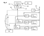
- FIG. 4 shown parallel connection of pressure check valve units to protect various partial memory corresponds largely to the example in FIG. 1 but has a parallel arrangement of the two separate pressure check valve units DSV and accumulator tank S2, S3. Of the Tank neck 265 is designed for refueling at a filling station T with 350 bar dispensing pressure.
- FIG. 5 shows an example of a pressure accumulator system with a check valve SV in an application with parallel arrangement of two accumulator tank S and positioning the check valve SV in front of a storage valve block 50.
- the filler neck unit 270 is installed in a body 60 of a motor vehicle and has a tank neck 265 on.
- the medium flows through a filter 29 and a check valve 28 in the branched pressure line 266.
- a branch of the pressure line 266 leads via a first accumulator valve block 50 with built-in check valve 28 in an accumulator tank S with 700 bar allowable filling pressure.
- the first accumulator valve block 50 additionally has a pressure regulator.
- the other branch leads into a radially arranged inlet opening 10 of a blocking bar SV designed for 200 bar barrier pressure.
- medium now passes with a maximum pressure of 200 bar via a second storage valve block 50, which also has a pressure regulator for removal of medium, in a permissible for 200 bar filling pressure second accumulator tank S.
- FIG. 6 shows by way of example a pressure storage system in which the pressure line 266 of the tank neck unit 270 without branching to a storage valve block 50 of a first pressure storage tank S (700 bar allowable operating pressure) leads. From an inlet region of the accumulator valve block 50, a further pressure line 267 leads to a subordinate second accumulator tank S (350 bar permissible operating pressure) whereby the inventive pressure check valve unit DSV with integrated removal valve secures the pressure accumulator system by closing the pressure check valve unit DSV upon reaching the preset 350 bar barrier pressure.
- a first pressure storage tank S 700 bar allowable operating pressure
- An opening of the pressure check valve unit DSV takes place only when the pressure in the first pressure storage tank and thus also in the connecting line between the pressure storage tanks by removal of medium below the barrier pressure (350 bar) of the pressure check valve unit DSV drops.
- the emptying of the pressure accumulator system is effected by a pressure regulator integrated in the accumulator valve block 50 and a pressure line 255 to a consumer.
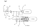
- FIG. 7 Shows by way of example an accumulator system comprising a combination of a shut-off valve SV with electromagnetically operable valves in an application with a parallel arrangement of two accumulator tank S with different allowable operating pressures.
- the filler neck unit 270 (according to the prior art) is installed in a body 60 of a motor vehicle and has a filler neck 265 on. During the filling process, the medium flows through a filter 29 and a check valve 28 in the branched pressure line 266th
- a branch of the pressure line 266 leads via a first storage valve block 53 with built-in safety valve and check valve 28 into the first pressure storage tank S with 700 bar allowable filling pressure.
- the first accumulator valve block 53 additionally has a pressure line 267, wherein the pressure line 267 leads as a sampling line to a pressure regulator 52.
- the other branch of the pressure line 266 leads into a radially arranged inlet opening 10 of a blocking bar SV designed for a blocking pressure of 350 bar, which is connected with its outlet opening 11 directly to a second pressure storage tank S with a filling pressure of 350 bar.
- This in Fig. 7 Shut-off valve SV shown has additionally in the region of the sealing body on an opening which is connected to an electromagnetically actuated shut-off valve 51.
- the electromagnetically actuated shut-off valve 51 is here a solenoid valve that can be opened and closed electrically. Downstream of the electromagnetically actuated shut-off valve 51 is a pressure regulator 52. In the connecting line between the electromagnetically actuated shut-off valve 51 and the pressure regulator 52, the connecting line coming from the first pressure storage container S opens.
- This connection line has a pressure sensor P on.
- the electromagnetically actuated shut-off valve 51 allows the removal of medium from the second pressure storage tank S with 350 bar allowable filling pressure as soon as the pressure in the connecting line has dropped below the blocking pressure of the check valve SV.
- the check valve according to the invention via a valve receiving block 27 in a Publ tion of an accumulator tank S is arranged.
- a check valve here the entirety of the filling process controlling parts of the pressure check valve unit according to the invention is referred to.
- a valve housing 20 a piston 22 is mounted, which has two sections with different outer diameters D2, D3 and designed as a central hollow bore connecting channel 14 with the inner diameter D 1.
- the piston 22 is supported at the transition to the larger outer diameter D3 on the support A3 by a spring 23 on the valve housing 20, whereby the piston 22 is held in abutment with the cover 24 and thereby in a pressureless installation state, the passage opening 13 in the open position.
- the cylindrical piston has in the embodiment shown two sections with different outer diameters D2 and D3.
- a first piston section has a first piston active surface A1, which is formed normal to the axis of the piston 22, has a sealing edge formed as a chamfer on an edge of the piston, and a first sliding surface with an outer diameter D2.
- a second piston section has a second piston acting surface A2, a support A3 for the spring 23 and a second sliding surface with an outer diameter D3.
- the connecting channel 14 is formed as an axial bore over the entire length of the piston 22 and has an inner diameter D 1.
- the connecting channel 14 connects the two piston reaction surfaces A1, A2 and is corresponding to the Embodiment of the valve housing 20 and the operating state of the check valve flows through the medium.
- the piston 22 is sealed in the two sections with different outer diameters D2, D3 of sealing elements 41,42 so that the space with the spring 23 between these seals can breathe freely through the ventilation opening 12 to atmospheric pressure.
- the sealing elements 41, 42 may optionally be mounted in the piston 22 or as shown in the valve housing 20.
- the seal 43 seals the adjustable cover 24 against the valve housing 20.
- medium can flow through the inlet opening 10 in the inlet region 17 of the valve chamber via the passage opening 13 and through the connecting channel 14 into the storage area 19 of the valve chamber, and subsequently through the outlet opening 11 in FIG get the subsequent accumulator tank S.
- the piston 22 overcomes the spring force 23, the piston 22 is pushed against the sealing body 21.
- the check valve closes. This pressure corresponds to the barrier pressure.
- the piston at the outer diameter D2 to the sealing body 21 seals.
- the check valve remains closed because the pressure increase no longer acts on the first piston effective area A1.
- the valve still remains closed, as the closing force by the Pressure in the outlet opening 11 on the piston effective area A2, minus the spring force of the spring 23, is determined and this state has not changed.
- the spring force of the spring 23 is additionally adjustable with the depth of engagement of the lid 24. In order to obtain a good pressure distribution to the second piston effective area A2 are either spacer 25 on the cover 24 or represent appropriate exemptions on the piston.
- FIG. 9 shows an example of a complete pressure check valve unit according to the invention. This essentially covers all parts of the Fig. 8 shown blocking valve with the same reference numerals.
- the modified valve housing is designated here by the reference numeral 26 and has an exemplary removal channel 15 shown between the storage area 19 and the inlet opening 10 in which a removal valve 30 is arranged that opens and closes according to the pressure conditions.
- An advantageous embodiment results in the embodiment of the removal valve 30 as a mechanical ball valve, wherein the ball valve is permanently closed by a spring 31 without pressure.
- the removal valve 30 can open and medium flows from the storage area 19 through the withdrawal channel 15 and the channel 16 in the spring -Fixierschraube 32 back to the inlet opening 10 back. Only then is a removal of medium from the downstream pressure storage system possible, provided that the downstream pressure storage system has no further removal devices. As a result, the pressure in the storage area 19 decreases and, depending on the spring hysteresis of the spring 23 and the friction of the sealing elements 41, 42, the piston 22 is pressed downwards by the check valve in a time-delayed manner Passage opening 13 is released.
- the gasket 48 seals a bleed valve 30 screwed as an assembly against the valve body 26.
- the bleed valve can also be used in combination with electromagnetic valves and a pressure sensor P for arbitrary control of the timing for opening the pressure check valve unit.
- the backup of the screwed lid 24 and thus the secure determination of the barrier pressure can be as technically usual z. B. be achieved with a clamping screw 35. Necessary holes can be sealed by screws with sealing rings 33 and 34, also as is technically customary, to the outside.
- An ideal complement is a combination of pressure check valve unit with a pressure relief valve 36 in a common valve housing 26 between the conduit on the removal channel 15 and serving as a space for the spring 23 relief region 18 with relief opening 12.
- the safe removal of escaping medium eliminates any further safety-critical factor ,
- Opening of the check valve takes place only when the pressure in the outlet opening 11 drops due to the fact that medium is removed in the subsequent system via a separate location and thereby the pressure drops below the barrier pressure.
- the check valve opens either by the pressure in the storage area 19 drops below the closing pressure of the check valve by removal from the accumulator tank by the consumer or by means of the in Fig. 9 shown in the removal channel 15,15a arranged removal valve 30th
- FIG. 8 A further variant of a shut-off valve SV according to the invention, not shown in the figures, varies from FIG Fig. 8 illustrated embodiment.
- the in the Fig. 8 arranged in the cover 24 outlet opening 11 is moved into the valve housing 20 in alignment with the axis of movement of the piston 22 under the sealing body 23.
- the lid 24 closes the valve chamber now without the outlet opening tight.
- the sealing body 21 In all embodiments in which a sealing body 21 is used, the sealing body 21 must be sealed to the valve housing 20 for safety reasons, so that no additional forces arise and can act on the sealing edge of the piston 22.
- the invention is suitable both for stationary pressure accumulator systems and for pressure accumulator systems in vehicles.
- vehicle in this patent includes, for example, motor vehicles, rail vehicles, and water and air vehicles. All stated pressures are exemplary and do not limit the invention and the range of pressures for which the invention is claimed.
Landscapes
- Engineering & Computer Science (AREA)
- Mechanical Engineering (AREA)
- General Engineering & Computer Science (AREA)
- Physics & Mathematics (AREA)
- Fluid Mechanics (AREA)
- Filling Or Discharging Of Gas Storage Vessels (AREA)
- Supply Devices, Intensifiers, Converters, And Telemotors (AREA)
Priority Applications (6)
| Application Number | Priority Date | Filing Date | Title |
|---|---|---|---|
| EP12191303.2A EP2728242B1 (fr) | 2012-11-05 | 2012-11-05 | Système d'accumulation de pression et procédé de fonctionnement d'un système d'accumulation de pression |
| JP2013227823A JP5792259B2 (ja) | 2012-11-05 | 2013-11-01 | 蓄圧システムおよび蓄圧システムの動作方法 |
| KR20130132749A KR20140058362A (ko) | 2012-11-05 | 2013-11-04 | 압력 저장 시스템 및 압력 저장 시스템의 동작 방법 |
| US14/072,730 US9328745B2 (en) | 2012-11-05 | 2013-11-05 | Pressure storage system and method to operate pressure storage system |
| CN201310757342.3A CN103863096B (zh) | 2012-11-05 | 2013-11-05 | 蓄压系统及操作该蓄压系统的方法 |
| JP2015153989A JP2016028209A (ja) | 2012-11-05 | 2015-08-04 | 蓄圧システムおよび蓄圧システムの動作方法 |
Applications Claiming Priority (1)
| Application Number | Priority Date | Filing Date | Title |
|---|---|---|---|
| EP12191303.2A EP2728242B1 (fr) | 2012-11-05 | 2012-11-05 | Système d'accumulation de pression et procédé de fonctionnement d'un système d'accumulation de pression |
Publications (2)
| Publication Number | Publication Date |
|---|---|
| EP2728242A1 true EP2728242A1 (fr) | 2014-05-07 |
| EP2728242B1 EP2728242B1 (fr) | 2021-08-25 |
Family
ID=47172460
Family Applications (1)
| Application Number | Title | Priority Date | Filing Date |
|---|---|---|---|
| EP12191303.2A Active EP2728242B1 (fr) | 2012-11-05 | 2012-11-05 | Système d'accumulation de pression et procédé de fonctionnement d'un système d'accumulation de pression |
Country Status (5)
| Country | Link |
|---|---|
| US (1) | US9328745B2 (fr) |
| EP (1) | EP2728242B1 (fr) |
| JP (2) | JP5792259B2 (fr) |
| KR (1) | KR20140058362A (fr) |
| CN (1) | CN103863096B (fr) |
Cited By (1)
| Publication number | Priority date | Publication date | Assignee | Title |
|---|---|---|---|---|
| DE102017201746A1 (de) * | 2017-02-03 | 2018-08-09 | Bayerische Motoren Werke Aktiengesellschaft | Tankvorrichtung und damit ausgestattetes Fahrzeug |
Families Citing this family (56)
| Publication number | Priority date | Publication date | Assignee | Title |
|---|---|---|---|---|
| DE102012218857A1 (de) * | 2012-10-16 | 2014-04-17 | Bayerische Motoren Werke Aktiengesellschaft | Verfahren zum Befüllen einer Kraftstoffspeicheranlage eines Kraftfahrzeugs |
| DE102013017875A1 (de) * | 2013-10-26 | 2015-05-21 | Wabco Gmbh | Relaisventil, Ventileinrichtung sowie Fahrzeug damit |
| DE102014210242B4 (de) * | 2014-05-28 | 2024-06-06 | Bayerische Motoren Werke Aktiengesellschaft | Drucktankanordnung |
| JP6389440B2 (ja) * | 2015-03-13 | 2018-09-12 | 株式会社神戸製鋼所 | ガス供給システムおよびそれを備えた水素ステーション、蓄圧器の寿命判定方法、並びにガス供給システムの使用方法 |
| US10895325B2 (en) | 2015-09-29 | 2021-01-19 | Kerr Machine Co. | Sealing high pressure flow devices |
| US10670013B2 (en) | 2017-07-14 | 2020-06-02 | Kerr Machine Co. | Fluid end assembly |
| US11536378B2 (en) | 2015-09-29 | 2022-12-27 | Kerr Machine Co. | Sealing high pressure flow devices |
| US11486502B2 (en) | 2015-09-29 | 2022-11-01 | Kerr Machine Co. | Sealing high pressure flow devices |
| US20200232450A9 (en) | 2015-09-29 | 2020-07-23 | Kerr Machine Co. | Multi-Piece Fluid End |
| US10591101B2 (en) * | 2016-01-23 | 2020-03-17 | Ronald E. Smith | Pulsation dampening system for high-pressure fluid lines |
| DE102016110855A1 (de) * | 2016-06-14 | 2017-12-14 | Dr. Ing. H.C. F. Porsche Aktiengesellschaft | Druckhalteventil für ein reversibles Verbinden mit einer Luftleitung |
| CN107725497B (zh) * | 2016-08-12 | 2019-09-06 | 大连精维液压技术有限公司 | 稳压式大容量蓄能器 |
| JP6875851B2 (ja) * | 2016-12-27 | 2021-05-26 | 川崎重工業株式会社 | バルブブロック、及びそれを備えるタンク装置 |
| CN110382944B (zh) * | 2017-03-30 | 2021-10-01 | 全耐塑料高级创新研究公司 | 氢气存储系统 |
| US11536267B2 (en) | 2017-07-14 | 2022-12-27 | Kerr Machine Co. | Fluid end assembly |
| US10962001B2 (en) * | 2017-07-14 | 2021-03-30 | Kerr Machine Co. | Fluid end assembly |
| US11708830B2 (en) | 2017-12-11 | 2023-07-25 | Kerr Machine Co. | Multi-piece fluid end |
| US20190383409A1 (en) * | 2018-06-19 | 2019-12-19 | Emerson Process Management Regulator Technologies, Inc. | Slam-shut safety device for use in dirty service applications |
| IT201800007629A1 (it) * | 2018-07-30 | 2020-01-30 | Pietro Fiorentini Spa | Impianto riduttore di pressione con due o piu’ linee operanti in parallelo |
| WO2020123431A1 (fr) | 2018-12-10 | 2020-06-18 | Kerr Machine Co. | Extrémité de fluide |
| USD916240S1 (en) | 2018-12-10 | 2021-04-13 | Kerr Machine Co. | Fluid end |
| US11788527B2 (en) | 2018-12-10 | 2023-10-17 | Kerr Machine Co. | Fluid end |
| US11578710B2 (en) | 2019-05-02 | 2023-02-14 | Kerr Machine Co. | Fracturing pump with in-line fluid end |
| US12345254B2 (en) | 2019-11-18 | 2025-07-01 | Kerr Machine Co. | Fluid end assembly |
| US11635068B2 (en) | 2019-11-18 | 2023-04-25 | Kerr Machine Co. | Modular power end |
| US12000257B2 (en) | 2022-10-17 | 2024-06-04 | Kerr Machine Co. | Fluid end |
| US11578711B2 (en) | 2019-11-18 | 2023-02-14 | Kerr Machine Co. | Fluid routing plug |
| US11686296B2 (en) | 2019-11-18 | 2023-06-27 | Kerr Machine Co. | Fluid routing plug |
| WO2021102001A1 (fr) | 2019-11-18 | 2021-05-27 | Kerr Machine Co. | Bouchon d'acheminement de fluide |
| US12523205B2 (en) | 2019-11-18 | 2026-01-13 | Kerr Machine Co. | Fluid routing plug |
| US11644018B2 (en) | 2019-11-18 | 2023-05-09 | Kerr Machine Co. | Fluid end |
| US12135024B2 (en) | 2019-11-18 | 2024-11-05 | Kerr Machine Co. | Fluid end assembly |
| US12264661B2 (en) | 2019-11-18 | 2025-04-01 | Kerr Machine Co. | High pressure pump |
| US12292040B2 (en) | 2019-11-18 | 2025-05-06 | Kerr Machine Co. | High pressure pump |
| US12421961B2 (en) | 2019-11-18 | 2025-09-23 | Kerr Machine Co. | Fluid routing plug |
| US12188458B2 (en) | 2019-11-18 | 2025-01-07 | Kerr Machine Co. | Fluid end assembly |
| DE102020201173A1 (de) * | 2020-01-31 | 2021-08-05 | Robert Bosch Gesellschaft mit beschränkter Haftung | Druckgesteuertes Absperrventil für ein Brennstoffzellensystem, Brennstoffzellensystem |
| USD1034909S1 (en) | 2020-11-18 | 2024-07-09 | Kerr Machine Co. | Crosshead frame |
| USD1120985S1 (en) | 2020-11-18 | 2026-03-31 | Kerr Machine Co. | High pressure pump |
| USD1061819S1 (en) | 2020-11-18 | 2025-02-11 | Kerr Machine Co. | Fluid routing plug |
| CN112814865A (zh) * | 2021-02-04 | 2021-05-18 | 中交第四公路工程局有限公司 | 泵送系统及混凝土泵送设备 |
| US11920583B2 (en) | 2021-03-05 | 2024-03-05 | Kerr Machine Co. | Fluid end with clamped retention |
| US12565902B2 (en) * | 2021-03-31 | 2026-03-03 | Eagle Industry Co., Ltd. | Fluid circuit |
| EP4105542B1 (fr) * | 2021-06-15 | 2026-05-06 | L'Air Liquide, société anonyme pour l'Étude et l'Exploitation des procédés Georges Claude | Dispositif de réduction de la pression |
| US11946465B2 (en) | 2021-08-14 | 2024-04-02 | Kerr Machine Co. | Packing seal assembly |
| IT202100028586A1 (it) * | 2021-11-10 | 2023-05-10 | Bosch Gmbh Robert | Gruppo di alimentazione per alimentare idrogeno ad un sistema di propulsione ad idrogeno |
| US11808364B2 (en) | 2021-11-11 | 2023-11-07 | Kerr Machine Co. | Valve body |
| US12516594B2 (en) | 2022-10-17 | 2026-01-06 | Kerr Machine Co. | Fluid end |
| KR20240154926A (ko) * | 2023-04-19 | 2024-10-28 | 현대자동차주식회사 | 유량 분배 장치 및 이를 포함하는 차량용 유체 충전 시스템 |
| US12297827B2 (en) | 2023-06-05 | 2025-05-13 | Kerr Machine Co. | Fluid end with clamped retention |
| DE102023126000A1 (de) * | 2023-09-26 | 2025-03-27 | Friedrich Müller | Druckentlastetes Ventil |
| US12404857B2 (en) | 2023-11-27 | 2025-09-02 | Kerr Machine Co. | Cooling sleeve for use with a fluid end |
| US20250231091A1 (en) * | 2024-01-11 | 2025-07-17 | Hydrocarbon Analytics LLC | Light hydrocarbon sampling system and methods of use thereof |
| DE102024201997A1 (de) * | 2024-03-04 | 2025-09-04 | Robert Bosch Gesellschaft mit beschränkter Haftung | Tanksystem zum Speichern eines Fluids |
| US12607185B2 (en) | 2024-03-08 | 2026-04-21 | Kerr Machine Co. | Fluid end with threaded dynamic section |
| US12590581B2 (en) | 2024-03-08 | 2026-03-31 | Kerr Machine Co. | Fluid end with threaded dynamic section |
Citations (6)
| Publication number | Priority date | Publication date | Assignee | Title |
|---|---|---|---|---|
| EP1653148A1 (fr) * | 2003-07-25 | 2006-05-03 | Toyota Jidosha Kabushiki Kaisha | Systeme d'alimentation en gaz |
| JP2007170443A (ja) * | 2005-12-19 | 2007-07-05 | Honda Motor Co Ltd | 水素自動車のガスの使用及び補給システム |
| WO2009006852A1 (fr) * | 2007-07-12 | 2009-01-15 | Huanen Xu | Système d'alimentation de gaz sécurisé intelligent et basse consommation pour réservoirs de gaz |
| DE102009049687A1 (de) | 2009-10-20 | 2011-04-21 | Daimler Ag | Gasbehälteranordnung und Verfahren zum Betreiben einer Gasbehälteranordnung |
| WO2011049466A1 (fr) * | 2009-10-21 | 2011-04-28 | Statoil Asa | Procédé de fonctionnement et de commande de remplissage de gaz |
| WO2011138826A1 (fr) * | 2010-05-06 | 2011-11-10 | トヨタ自動車株式会社 | Système de remplissage d'hydrogène |
Family Cites Families (16)
| Publication number | Priority date | Publication date | Assignee | Title |
|---|---|---|---|---|
| US3890999A (en) * | 1972-12-15 | 1975-06-24 | Eugene D Moskow | Fluid pressure regulator |
| US4380242A (en) * | 1979-10-26 | 1983-04-19 | Texas Gas Transport Company | Method and system for distributing natural gas |
| JP3571453B2 (ja) * | 1996-03-19 | 2004-09-29 | トキコテクノ株式会社 | ガス供給装置 |
| JP2001295994A (ja) | 2000-04-11 | 2001-10-26 | Air Liquide Japan Ltd | 圧縮ガスの移充填方法 |
| JP2005207561A (ja) * | 2004-01-26 | 2005-08-04 | Honda Motor Co Ltd | 燃料ガススタンド及び燃料ガス供給方法 |
| US7325561B2 (en) * | 2004-12-02 | 2008-02-05 | Honda Motor Co., Ltd. | Hydrogen vehicle gas utilization and refueling system |
| CN201007425Y (zh) * | 2006-12-30 | 2008-01-16 | 郑州科林石油设备有限公司 | 气源压力自识别压缩天然气加气机 |
| US7987877B2 (en) * | 2007-12-14 | 2011-08-02 | Texaco Inc. | Method for managing storage of gaseous hydrogen |
| NO330021B1 (no) * | 2009-02-11 | 2011-02-07 | Statoil Asa | Anlegg for lagring og tilforsel av komprimert gass |
| US8443820B2 (en) * | 2009-06-03 | 2013-05-21 | Ford Global Technologies, Llc | Fuel distribution in multi-fuel tank compressed gas fuel systems |
| JP2011074925A (ja) * | 2009-09-29 | 2011-04-14 | Taiyo Nippon Sanso Corp | 水素ガスの充填方法及び充填装置 |
| DE112010004411B4 (de) * | 2009-11-16 | 2017-10-19 | Toyota Jidosha Kabushiki Kaisha | Brenngasfüllverfahren |
| JP5534192B2 (ja) * | 2010-04-09 | 2014-06-25 | トヨタ自動車株式会社 | ガスタンクシステム及び車両 |
| CN101886737B (zh) * | 2010-06-24 | 2012-07-04 | 上海穗杉实业有限公司 | 一种集成的流体灌充控制方法及其装置 |
| JP5048814B2 (ja) * | 2010-07-20 | 2012-10-17 | 本田技研工業株式会社 | 水素充填システムの運転方法 |
| JP5732801B2 (ja) * | 2010-09-30 | 2015-06-10 | トヨタ自動車株式会社 | ガス充填対象物、ガス供給装置、ガス供給システム、弁の状態の判定方法、および、ガスの供給方法 |
-
2012
- 2012-11-05 EP EP12191303.2A patent/EP2728242B1/fr active Active
-
2013
- 2013-11-01 JP JP2013227823A patent/JP5792259B2/ja not_active Expired - Fee Related
- 2013-11-04 KR KR20130132749A patent/KR20140058362A/ko not_active Abandoned
- 2013-11-05 US US14/072,730 patent/US9328745B2/en active Active
- 2013-11-05 CN CN201310757342.3A patent/CN103863096B/zh active Active
-
2015
- 2015-08-04 JP JP2015153989A patent/JP2016028209A/ja not_active Withdrawn
Patent Citations (6)
| Publication number | Priority date | Publication date | Assignee | Title |
|---|---|---|---|---|
| EP1653148A1 (fr) * | 2003-07-25 | 2006-05-03 | Toyota Jidosha Kabushiki Kaisha | Systeme d'alimentation en gaz |
| JP2007170443A (ja) * | 2005-12-19 | 2007-07-05 | Honda Motor Co Ltd | 水素自動車のガスの使用及び補給システム |
| WO2009006852A1 (fr) * | 2007-07-12 | 2009-01-15 | Huanen Xu | Système d'alimentation de gaz sécurisé intelligent et basse consommation pour réservoirs de gaz |
| DE102009049687A1 (de) | 2009-10-20 | 2011-04-21 | Daimler Ag | Gasbehälteranordnung und Verfahren zum Betreiben einer Gasbehälteranordnung |
| WO2011049466A1 (fr) * | 2009-10-21 | 2011-04-28 | Statoil Asa | Procédé de fonctionnement et de commande de remplissage de gaz |
| WO2011138826A1 (fr) * | 2010-05-06 | 2011-11-10 | トヨタ自動車株式会社 | Système de remplissage d'hydrogène |
Cited By (1)
| Publication number | Priority date | Publication date | Assignee | Title |
|---|---|---|---|---|
| DE102017201746A1 (de) * | 2017-02-03 | 2018-08-09 | Bayerische Motoren Werke Aktiengesellschaft | Tankvorrichtung und damit ausgestattetes Fahrzeug |
Also Published As
| Publication number | Publication date |
|---|---|
| EP2728242B1 (fr) | 2021-08-25 |
| KR20140058362A (ko) | 2014-05-14 |
| JP5792259B2 (ja) | 2015-10-07 |
| CN103863096A (zh) | 2014-06-18 |
| JP2016028209A (ja) | 2016-02-25 |
| US20140124039A1 (en) | 2014-05-08 |
| JP2014092281A (ja) | 2014-05-19 |
| US9328745B2 (en) | 2016-05-03 |
| CN103863096B (zh) | 2017-04-12 |
Similar Documents
| Publication | Publication Date | Title |
|---|---|---|
| EP2728242B1 (fr) | Système d'accumulation de pression et procédé de fonctionnement d'un système d'accumulation de pression | |
| EP2927549B1 (fr) | Unité à clapet anti-retour pour un réservoir d'accumulation de pression | |
| EP2728241B1 (fr) | Unité de manchon de citerne avec clapet antiretour | |
| EP2728228B1 (fr) | Clapet antiretour pour un réservoir d'accumulation de pression | |
| EP3479008B1 (fr) | Soupape de réservoir | |
| DE102006017541B4 (de) | Verfahren zum Austrag von Hochdruckspeicherbehältern | |
| DE102020201172A1 (de) | Vorrichtung zum Speichern von Druckgas, Fahrzeug | |
| EP2331809B1 (fr) | Installation d'alimentation en carburant pour systèmes d'injection d'huile lourde à rampe commune | |
| DE102017213521A1 (de) | Ventil-Vorrichtung für einen Speicherbehälter | |
| DE102021205684A1 (de) | Absperrventil für Wasserstofftanksysteme, Wasserstofftanksystem sowie Verwendung eines Absperrventils in einem Wasserstofftanksystem | |
| DE102022131274A1 (de) | Wasserstoffversorgungssystem für ein Kraftfahrzeug | |
| EP0473555A2 (fr) | Améliorations des récipients à gaz liquéfié et leur vanne distributrice, en particulier leur utilisation dans un camping-car et similaires | |
| WO2024028013A1 (fr) | Ensemble soupape pour un réservoir de gaz combustible, réservoir de gaz combustible comprenant un ensemble soupape et système de réservoir de gaz combustible | |
| WO2018114274A1 (fr) | Dispositif de dosage d'un combustible gazeux vers un injecteur | |
| DE102016115360A1 (de) | Überströmventil zum zumindest teilweisen Verschließen und Öffnen eines Fluidleitungssystems | |
| WO2024240568A1 (fr) | Ensemble soupape de réservoir et procédé de remplissage d'un accumulateur de gaz sous pression | |
| DE102014018360A1 (de) | Thermisch auslösendes Sicherheitsventil | |
| EP4565815A1 (fr) | Procédé de fonctionnement et/ou de remplissage d'un système d'alimentation en gaz sous pression et dispositif électronique | |
| DE102011005286B4 (de) | Verfahren zum Betreiben einer Brennkraftmaschine und Brennkraftmaschine | |
| DE102014006029C5 (de) | Austragsystem | |
| DE102016008106A1 (de) | Tankventil | |
| DE3146535A1 (de) | "steuerungsvorrichtung fuer einen verdichter" | |
| EP1846690B1 (fr) | Vehicule automobile fonctionnant avec du carburant stocke cryogeniquement et muni d'un systeme a air comprime | |
| WO2015128326A1 (fr) | Soupape de réduction de pression pour une installation d'extinction d'incendie, ainsi qu'installation d'extinction d'incendie équipée d'une soupape de réduction de pression de ce type | |
| DE102024202945A1 (de) | Sicherheitsmagnetventileinrichtung und Verfahren zum Betreiben einer Sicherheitsmagnetventileinrichtung |
Legal Events
| Date | Code | Title | Description |
|---|---|---|---|
| PUAI | Public reference made under article 153(3) epc to a published international application that has entered the european phase |
Free format text: ORIGINAL CODE: 0009012 |
|
| 17P | Request for examination filed |
Effective date: 20121220 |
|
| AK | Designated contracting states |
Kind code of ref document: A1 Designated state(s): AL AT BE BG CH CY CZ DE DK EE ES FI FR GB GR HR HU IE IS IT LI LT LU LV MC MK MT NL NO PL PT RO RS SE SI SK SM TR |
|
| AX | Request for extension of the european patent |
Extension state: BA ME |
|
| RBV | Designated contracting states (corrected) |
Designated state(s): AL AT BE BG CH CY CZ DE DK EE ES FI FR GB GR HR HU IE IS IT LI LT LU LV MC MK MT NL NO PL PT RO RS SE SI SK SM TR |
|
| RIC1 | Information provided on ipc code assigned before grant |
Ipc: F15B 1/04 20060101ALI20150223BHEP Ipc: F17C 5/00 20060101AFI20150223BHEP Ipc: F17C 7/00 20060101ALI20150223BHEP |
|
| 17Q | First examination report despatched |
Effective date: 20160324 |
|
| GRAP | Despatch of communication of intention to grant a patent |
Free format text: ORIGINAL CODE: EPIDOSNIGR1 |
|
| STAA | Information on the status of an ep patent application or granted ep patent |
Free format text: STATUS: GRANT OF PATENT IS INTENDED |
|
| INTG | Intention to grant announced |
Effective date: 20210406 |
|
| RIN1 | Information on inventor provided before grant (corrected) |
Inventor name: MAYR, FRANZ Inventor name: BARTLOK, GUIDO |
|
| GRAS | Grant fee paid |
Free format text: ORIGINAL CODE: EPIDOSNIGR3 |
|
| GRAA | (expected) grant |
Free format text: ORIGINAL CODE: 0009210 |
|
| STAA | Information on the status of an ep patent application or granted ep patent |
Free format text: STATUS: THE PATENT HAS BEEN GRANTED |
|
| AK | Designated contracting states |
Kind code of ref document: B1 Designated state(s): AL AT BE BG CH CY CZ DE DK EE ES FI FR GB GR HR HU IE IS IT LI LT LU LV MC MK MT NL NO PL PT RO RS SE SI SK SM TR |
|
| REG | Reference to a national code |
Ref country code: GB Ref legal event code: FG4D Free format text: NOT ENGLISH |
|
| REG | Reference to a national code |
Ref country code: CH Ref legal event code: EP |
|
| REG | Reference to a national code |
Ref country code: DE Ref legal event code: R096 Ref document number: 502012016879 Country of ref document: DE |
|
| REG | Reference to a national code |
Ref country code: IE Ref legal event code: FG4D Free format text: LANGUAGE OF EP DOCUMENT: GERMAN Ref country code: AT Ref legal event code: REF Ref document number: 1424148 Country of ref document: AT Kind code of ref document: T Effective date: 20210915 |
|
| REG | Reference to a national code |
Ref country code: LT Ref legal event code: MG9D |
|
| REG | Reference to a national code |
Ref country code: NL Ref legal event code: MP Effective date: 20210825 |
|
| PG25 | Lapsed in a contracting state [announced via postgrant information from national office to epo] |
Ref country code: HR Free format text: LAPSE BECAUSE OF FAILURE TO SUBMIT A TRANSLATION OF THE DESCRIPTION OR TO PAY THE FEE WITHIN THE PRESCRIBED TIME-LIMIT Effective date: 20210825 Ref country code: SE Free format text: LAPSE BECAUSE OF FAILURE TO SUBMIT A TRANSLATION OF THE DESCRIPTION OR TO PAY THE FEE WITHIN THE PRESCRIBED TIME-LIMIT Effective date: 20210825 Ref country code: BG Free format text: LAPSE BECAUSE OF FAILURE TO SUBMIT A TRANSLATION OF THE DESCRIPTION OR TO PAY THE FEE WITHIN THE PRESCRIBED TIME-LIMIT Effective date: 20211125 Ref country code: LT Free format text: LAPSE BECAUSE OF FAILURE TO SUBMIT A TRANSLATION OF THE DESCRIPTION OR TO PAY THE FEE WITHIN THE PRESCRIBED TIME-LIMIT Effective date: 20210825 Ref country code: PT Free format text: LAPSE BECAUSE OF FAILURE TO SUBMIT A TRANSLATION OF THE DESCRIPTION OR TO PAY THE FEE WITHIN THE PRESCRIBED TIME-LIMIT Effective date: 20211227 Ref country code: NO Free format text: LAPSE BECAUSE OF FAILURE TO SUBMIT A TRANSLATION OF THE DESCRIPTION OR TO PAY THE FEE WITHIN THE PRESCRIBED TIME-LIMIT Effective date: 20211125 Ref country code: RS Free format text: LAPSE BECAUSE OF FAILURE TO SUBMIT A TRANSLATION OF THE DESCRIPTION OR TO PAY THE FEE WITHIN THE PRESCRIBED TIME-LIMIT Effective date: 20210825 Ref country code: FI Free format text: LAPSE BECAUSE OF FAILURE TO SUBMIT A TRANSLATION OF THE DESCRIPTION OR TO PAY THE FEE WITHIN THE PRESCRIBED TIME-LIMIT Effective date: 20210825 Ref country code: ES Free format text: LAPSE BECAUSE OF FAILURE TO SUBMIT A TRANSLATION OF THE DESCRIPTION OR TO PAY THE FEE WITHIN THE PRESCRIBED TIME-LIMIT Effective date: 20210825 |
|
| PG25 | Lapsed in a contracting state [announced via postgrant information from national office to epo] |
Ref country code: PL Free format text: LAPSE BECAUSE OF FAILURE TO SUBMIT A TRANSLATION OF THE DESCRIPTION OR TO PAY THE FEE WITHIN THE PRESCRIBED TIME-LIMIT Effective date: 20210825 Ref country code: LV Free format text: LAPSE BECAUSE OF FAILURE TO SUBMIT A TRANSLATION OF THE DESCRIPTION OR TO PAY THE FEE WITHIN THE PRESCRIBED TIME-LIMIT Effective date: 20210825 Ref country code: GR Free format text: LAPSE BECAUSE OF FAILURE TO SUBMIT A TRANSLATION OF THE DESCRIPTION OR TO PAY THE FEE WITHIN THE PRESCRIBED TIME-LIMIT Effective date: 20211126 |
|
| PG25 | Lapsed in a contracting state [announced via postgrant information from national office to epo] |
Ref country code: NL Free format text: LAPSE BECAUSE OF FAILURE TO SUBMIT A TRANSLATION OF THE DESCRIPTION OR TO PAY THE FEE WITHIN THE PRESCRIBED TIME-LIMIT Effective date: 20210825 |
|
| PG25 | Lapsed in a contracting state [announced via postgrant information from national office to epo] |
Ref country code: DK Free format text: LAPSE BECAUSE OF FAILURE TO SUBMIT A TRANSLATION OF THE DESCRIPTION OR TO PAY THE FEE WITHIN THE PRESCRIBED TIME-LIMIT Effective date: 20210825 |
|
| REG | Reference to a national code |
Ref country code: DE Ref legal event code: R097 Ref document number: 502012016879 Country of ref document: DE |
|
| PG25 | Lapsed in a contracting state [announced via postgrant information from national office to epo] |
Ref country code: SM Free format text: LAPSE BECAUSE OF FAILURE TO SUBMIT A TRANSLATION OF THE DESCRIPTION OR TO PAY THE FEE WITHIN THE PRESCRIBED TIME-LIMIT Effective date: 20210825 Ref country code: SK Free format text: LAPSE BECAUSE OF FAILURE TO SUBMIT A TRANSLATION OF THE DESCRIPTION OR TO PAY THE FEE WITHIN THE PRESCRIBED TIME-LIMIT Effective date: 20210825 Ref country code: RO Free format text: LAPSE BECAUSE OF FAILURE TO SUBMIT A TRANSLATION OF THE DESCRIPTION OR TO PAY THE FEE WITHIN THE PRESCRIBED TIME-LIMIT Effective date: 20210825 Ref country code: EE Free format text: LAPSE BECAUSE OF FAILURE TO SUBMIT A TRANSLATION OF THE DESCRIPTION OR TO PAY THE FEE WITHIN THE PRESCRIBED TIME-LIMIT Effective date: 20210825 Ref country code: CZ Free format text: LAPSE BECAUSE OF FAILURE TO SUBMIT A TRANSLATION OF THE DESCRIPTION OR TO PAY THE FEE WITHIN THE PRESCRIBED TIME-LIMIT Effective date: 20210825 Ref country code: AL Free format text: LAPSE BECAUSE OF FAILURE TO SUBMIT A TRANSLATION OF THE DESCRIPTION OR TO PAY THE FEE WITHIN THE PRESCRIBED TIME-LIMIT Effective date: 20210825 |
|
| PG25 | Lapsed in a contracting state [announced via postgrant information from national office to epo] |
Ref country code: MC Free format text: LAPSE BECAUSE OF FAILURE TO SUBMIT A TRANSLATION OF THE DESCRIPTION OR TO PAY THE FEE WITHIN THE PRESCRIBED TIME-LIMIT Effective date: 20210825 |
|
| REG | Reference to a national code |
Ref country code: CH Ref legal event code: PL |
|
| PLBE | No opposition filed within time limit |
Free format text: ORIGINAL CODE: 0009261 |
|
| STAA | Information on the status of an ep patent application or granted ep patent |
Free format text: STATUS: NO OPPOSITION FILED WITHIN TIME LIMIT |
|
| PG25 | Lapsed in a contracting state [announced via postgrant information from national office to epo] |
Ref country code: LU Free format text: LAPSE BECAUSE OF NON-PAYMENT OF DUE FEES Effective date: 20211105 Ref country code: IT Free format text: LAPSE BECAUSE OF FAILURE TO SUBMIT A TRANSLATION OF THE DESCRIPTION OR TO PAY THE FEE WITHIN THE PRESCRIBED TIME-LIMIT Effective date: 20210825 Ref country code: BE Free format text: LAPSE BECAUSE OF NON-PAYMENT OF DUE FEES Effective date: 20211130 |
|
| REG | Reference to a national code |
Ref country code: BE Ref legal event code: MM Effective date: 20211130 |
|
| 26N | No opposition filed |
Effective date: 20220527 |
|
| PG25 | Lapsed in a contracting state [announced via postgrant information from national office to epo] |
Ref country code: SI Free format text: LAPSE BECAUSE OF FAILURE TO SUBMIT A TRANSLATION OF THE DESCRIPTION OR TO PAY THE FEE WITHIN THE PRESCRIBED TIME-LIMIT Effective date: 20210825 Ref country code: LI Free format text: LAPSE BECAUSE OF NON-PAYMENT OF DUE FEES Effective date: 20211130 Ref country code: CH Free format text: LAPSE BECAUSE OF NON-PAYMENT OF DUE FEES Effective date: 20211130 |
|
| REG | Reference to a national code |
Ref country code: DE Ref legal event code: R081 Ref document number: 502012016879 Country of ref document: DE Owner name: MAGNA STEYR FAHRZEUGTECHNIK GMBH & CO KG, AT Free format text: FORMER OWNER: MAGNA STEYR FAHRZEUGTECHNIK AG & CO. KG, GRAZ, AT |
|
| PG25 | Lapsed in a contracting state [announced via postgrant information from national office to epo] |
Ref country code: IE Free format text: LAPSE BECAUSE OF NON-PAYMENT OF DUE FEES Effective date: 20211105 |
|
| REG | Reference to a national code |
Ref country code: AT Ref legal event code: MM01 Ref document number: 1424148 Country of ref document: AT Kind code of ref document: T Effective date: 20211105 |
|
| PG25 | Lapsed in a contracting state [announced via postgrant information from national office to epo] |
Ref country code: AT Free format text: LAPSE BECAUSE OF NON-PAYMENT OF DUE FEES Effective date: 20211105 |
|
| PG25 | Lapsed in a contracting state [announced via postgrant information from national office to epo] |
Ref country code: HU Free format text: LAPSE BECAUSE OF FAILURE TO SUBMIT A TRANSLATION OF THE DESCRIPTION OR TO PAY THE FEE WITHIN THE PRESCRIBED TIME-LIMIT; INVALID AB INITIO Effective date: 20121105 Ref country code: CY Free format text: LAPSE BECAUSE OF FAILURE TO SUBMIT A TRANSLATION OF THE DESCRIPTION OR TO PAY THE FEE WITHIN THE PRESCRIBED TIME-LIMIT Effective date: 20210825 |
|
| PG25 | Lapsed in a contracting state [announced via postgrant information from national office to epo] |
Ref country code: MK Free format text: LAPSE BECAUSE OF FAILURE TO SUBMIT A TRANSLATION OF THE DESCRIPTION OR TO PAY THE FEE WITHIN THE PRESCRIBED TIME-LIMIT Effective date: 20210825 |
|
| PG25 | Lapsed in a contracting state [announced via postgrant information from national office to epo] |
Ref country code: TR Free format text: LAPSE BECAUSE OF FAILURE TO SUBMIT A TRANSLATION OF THE DESCRIPTION OR TO PAY THE FEE WITHIN THE PRESCRIBED TIME-LIMIT Effective date: 20210825 |
|
| PG25 | Lapsed in a contracting state [announced via postgrant information from national office to epo] |
Ref country code: MT Free format text: LAPSE BECAUSE OF FAILURE TO SUBMIT A TRANSLATION OF THE DESCRIPTION OR TO PAY THE FEE WITHIN THE PRESCRIBED TIME-LIMIT Effective date: 20210825 |
|
| REG | Reference to a national code |
Ref country code: DE Ref legal event code: R082 Ref document number: 502012016879 Country of ref document: DE Representative=s name: EULER, MATTHIAS, DR., DE |
|
| PGFP | Annual fee paid to national office [announced via postgrant information from national office to epo] |
Ref country code: DE Payment date: 20251119 Year of fee payment: 14 |
|
| PGFP | Annual fee paid to national office [announced via postgrant information from national office to epo] |
Ref country code: GB Payment date: 20251121 Year of fee payment: 14 |
|
| PGFP | Annual fee paid to national office [announced via postgrant information from national office to epo] |
Ref country code: FR Payment date: 20251125 Year of fee payment: 14 |