EP2728546A2 - Verfahren und System zum Erfassen eines Objekts auf einer Straße - Google Patents
Verfahren und System zum Erfassen eines Objekts auf einer Straße Download PDFInfo
- Publication number
- EP2728546A2 EP2728546A2 EP20120192685 EP12192685A EP2728546A2 EP 2728546 A2 EP2728546 A2 EP 2728546A2 EP 20120192685 EP20120192685 EP 20120192685 EP 12192685 A EP12192685 A EP 12192685A EP 2728546 A2 EP2728546 A2 EP 2728546A2
- Authority
- EP
- European Patent Office
- Prior art keywords
- disparity
- disparity map
- sub
- image
- points
- Prior art date
- Legal status (The legal status is an assumption and is not a legal conclusion. Google has not performed a legal analysis and makes no representation as to the accuracy of the status listed.)
- Granted
Links
Images




Classifications
-
- G—PHYSICS
- G06—COMPUTING OR CALCULATING; COUNTING
- G06V—IMAGE OR VIDEO RECOGNITION OR UNDERSTANDING
- G06V20/00—Scenes; Scene-specific elements
- G06V20/60—Type of objects
- G06V20/64—Three-dimensional [3D] objects
- G06V20/647—Three-dimensional [3D] objects by matching two-dimensional images to three-dimensional objects
-
- H—ELECTRICITY
- H04—ELECTRIC COMMUNICATION TECHNIQUE
- H04N—PICTORIAL COMMUNICATION, e.g. TELEVISION
- H04N7/00—Television systems
- H04N7/18—Closed-circuit television [CCTV] systems, i.e. systems in which the video signal is not broadcast
-
- G—PHYSICS
- G06—COMPUTING OR CALCULATING; COUNTING
- G06T—IMAGE DATA PROCESSING OR GENERATION, IN GENERAL
- G06T7/00—Image analysis
- G06T7/70—Determining position or orientation of objects or cameras
- G06T7/73—Determining position or orientation of objects or cameras using feature-based methods
- G06T7/75—Determining position or orientation of objects or cameras using feature-based methods involving models
-
- G—PHYSICS
- G06—COMPUTING OR CALCULATING; COUNTING
- G06V—IMAGE OR VIDEO RECOGNITION OR UNDERSTANDING
- G06V20/00—Scenes; Scene-specific elements
- G06V20/50—Context or environment of the image
- G06V20/56—Context or environment of the image exterior to a vehicle by using sensors mounted on the vehicle
- G06V20/58—Recognition of moving objects or obstacles, e.g. vehicles or pedestrians; Recognition of traffic objects, e.g. traffic signs, traffic lights or roads
-
- G—PHYSICS
- G06—COMPUTING OR CALCULATING; COUNTING
- G06V—IMAGE OR VIDEO RECOGNITION OR UNDERSTANDING
- G06V20/00—Scenes; Scene-specific elements
- G06V20/50—Context or environment of the image
- G06V20/56—Context or environment of the image exterior to a vehicle by using sensors mounted on the vehicle
- G06V20/588—Recognition of the road, e.g. of lane markings; Recognition of the vehicle driving pattern in relation to the road
-
- H—ELECTRICITY
- H04—ELECTRIC COMMUNICATION TECHNIQUE
- H04N—PICTORIAL COMMUNICATION, e.g. TELEVISION
- H04N13/00—Stereoscopic video systems; Multi-view video systems; Details thereof
- H04N13/20—Image signal generators
- H04N13/204—Image signal generators using stereoscopic image cameras
-
- G—PHYSICS
- G06—COMPUTING OR CALCULATING; COUNTING
- G06T—IMAGE DATA PROCESSING OR GENERATION, IN GENERAL
- G06T2207/00—Indexing scheme for image analysis or image enhancement
- G06T2207/10—Image acquisition modality
- G06T2207/10028—Range image; Depth image; 3D point clouds
-
- G—PHYSICS
- G06—COMPUTING OR CALCULATING; COUNTING
- G06T—IMAGE DATA PROCESSING OR GENERATION, IN GENERAL
- G06T2207/00—Indexing scheme for image analysis or image enhancement
- G06T2207/30—Subject of image; Context of image processing
- G06T2207/30248—Vehicle exterior or interior
- G06T2207/30252—Vehicle exterior; Vicinity of vehicle
- G06T2207/30261—Obstacle
Definitions
- the present invention relates to a method and a system for detecting at least one object on a road, more particularly relates to a method and a system used in a vehicle for detecting at least one object on a road.
- a method in which an object approaching a vehicle of a driver (for example, a person or another vehicle) is detected by carrying out a grouping (clustering) process on the basis of a disparity map of a road surface, and then a warning message is reported to the driver, or the movement state of the driver's vehicle is auto-adjusted.
- a grouping process it is assumed that in a three-dimensional (3D) space, points in a same object domain are adjacent to each other, and the grouping process is carried out on the basis of distances and with regard to the whole disparity map. Since the grouping process is conducted on the whole disparity map, and only two frames of results are able to be obtained in one second, the method takes time, and diminishes the efficiency of dealing with an unforeseen accident. However, the method still has practical use.
- vehicle detection and recognition system provided by the BMWTM Group Research and Technology (published in “VISIGRAPH 2010 ").
- the system carries out vehicle detection on the basis of stereoscopic vision.
- vehicles are detected by using segmentation based on a mean shift clustering process;
- vehicle assumptions (candidates) covering the different vehicles are generated by using a U-V disparity algorithm.
- the processing speed in the system is 2.5 frames per second (obtained in a debug environment of a 3.2 GHz and 1 GB RAM desktop computer). Since the mean shift clustering process is utilized to divide an image, and the U-V disparity algorithm is utilized to seek an object, the system also takes time.
- US Patent No. US 7,729,512 B2 discloses a stereoscopic image processing method of detecting a moving object.
- a first image and a second image are obtained by sensing an image of a moving object from two different viewpoints by using a first imaging device and a second imaging device.
- Plural feature points are detected from the first image.
- a disparity distribution representing a disparity of each feature point is obtained by performing stereoscopic image processing using the first image and the second image.
- a threshold is determined for disparities in the disparity distribution.
- a feature point having a disparity exceeding the threshold in the disparity distribution is classified as an intra-moving-object feature point.
- An image area of the moving object in the first image is detected by using the intra-moving-object feature point.
- the method adopts a clustering approach, but the object detection based on brightness, used in the clustering approach is unreliable since a moving object having brightness being virtually the same with that of the surrounding environment cannot be detected in general. Particularly in a case where the disparity of an object is virtually the same with that of an adjacent roadside tree, the method cannot detect the object having the disparity being virtually the same with the disparity of the tree.
- a method and a system able to rapidly and accurately detect at least one object on the surface of a road needs to be proposed so that it is possible to more effectively achieve the driving assistance of a vehicle, and to report a warning message before an accident, so as to improve the driving safety.
- a method and a system for detecting the object on the basis of both the disparities of the road surface scene and a V-disparity image are provided in the embodiments of the present invention.
- V-disparity algorithm may simplify a division process of an obstacle and a road surface.
- V corresponds to the vertical coordinates in the image coordinate system of a disparity map.
- a longitudinal section of a road surface may be described as a piecewise linear curve, and an obstacle in a vertical plane may be projected as a vertical line.
- an extraction of a road surface and an obstacle in a 3D disparity map may be simplified as a 2D (two-dimensional) liner extraction in a V-disparity image.
- this kind of algorithm is not sensitive to interference such as lighting, shadows, or the like; consequently the algorithm is suitable for obstacle recognition for an intelligent vehicle, under a complex background.
- a V-disparity recognition process based on the two eyes of a human being mainly comprises three contents, namely, creating a V-disparity image, extracting a road surface, and extracting at least one vertical line representing an object on the road surface.
- a method of detecting at least one object on a road comprises a step of simultaneously capturing two depth maps of a current scene by adopting two depth cameras, and then calculating a disparity map of the current scene based on the two depth maps; a step of obtaining, based on the disparity map, a V-disparity image of the current scene by adopting a V-disparity algorithm; a step of detecting an oblique line in the V-disparity image, corresponding to the road in the disparity map, and then removing all of the points in the disparity map, corresponding to the oblique line detected in the V-disparity image, so as to acquire a sub-disparity map excluding the road; a step of detecting plural vertical lines in the V-disparity image, and then extracting, for each of the plural vertical lines, all of the points corresponding to this vertical line from the sub-disparity map excluding the road, to serve as an object sub-
- a Hough transform is utilized for detecting the oblique line in the V-disparity image, corresponding to the road in the disparity map.
- detecting each of the plural vertical lines in the V-disparity image is conducted by seeking continuous points having a same gray level not equal to zero, in the V-disparity image.
- detecting the oblique line in the V-disparity image, corresponding to the road in the disparity map, and then removing all of the points in the disparity map, corresponding to the oblique line detected in the V-disparity image includes a step of detecting the oblique line in the V-disparity image by adopting the Hough transform; a step of extending the oblique line so as to let it intersect with horizontal and vertical coordinate axes of the V-disparity image, respectively; a step of dividing, based on horizontal coordinate values of the oblique line, the oblique line into plural sub-line segments; and a step of removing, for each of the plural sub-line segments, all of the points in the disparity map, corresponding to this sub-line segment, wherein, all of the points are within a corresponding disparity range.
- the method further comprises, before carrying out the merging step, a step of performing a point clustering process with regard to each of the object sub-disparity maps.
- the method further comprises, before carrying out the point clustering process, a step of, for each of the object sub-disparity maps, conducting a smoothing process with regard to all of the points forming this object sub-disparity map, and then removing connection points in this object sub-disparity map.
- a system for detecting at least one object on a road comprising two depth cameras configured to simultaneously capture two depth maps of a current scene so as to calculate a disparity map of the current scene based on the two depth maps; a V-disparity map calculator configured to obtain, based on the disparity map, a V-disparity image of the current scene by adopting a V-disparity algorithm; a road extractor configured to detect an oblique line in the V-disparity image, corresponding to the road in the disparity map, and then to remove all of the points in the disparity map, corresponding to the oblique line detected in the V-disparity image, so as to acquire a sub-disparity map excluding the road; an object area detector configured to detect plural vertical lines in the V-disparity image, and then to extract, for each of the plural vertical lines, all of the points corresponding to this vertical line from the sub-disparity map excluding the road, to serve as an object
- the object area detector detects each of the plural vertical lines in the V-disparity image by seeking continuous points having a same gray level not equal to 0, in the V-disparity image.
- the road extractor detects the oblique line in the V-disparity image, corresponding to the road in the disparity map, and then removes all of the points in the disparity map, corresponding to the oblique line detected in the V-disparity image by carrying out a step of detecting the oblique line in the V-disparity image by adopting Hough transform; a step of extending the oblique line so as to let it intersect with horizontal and vertical coordinate axes of the V-disparity image, respectively; a step of dividing, based on horizontal coordinate values of the oblique line, the oblique line into plural sub-line segments; and a step of removing, for each of the plural sub-line segments, all of the points in the disparity map, corresponding to this sub-line segment, wherein, all of the points are within a corresponding disparity range.
- system further comprises a noise processor configured to, for each of the object sub-disparity maps, conduct a smoothing process with regard to all of the points forming this object sub-disparity map, and then to remove connection points in this object sub-disparity map; and a point clustering processor configured to perform a point clustering process with regard to each of the object sub-disparity maps after processed by the noise processor.
- the processing speed in the method and system is greater than those of the conventional techniques.
- a V-disparity image is adopted for seeking an object sub-disparity map including an object, and then the object is detected from the object sub-disparity map by using a simple clustering approach; as a result, this may significantly increase the detection accuracy.
- the method and system are based on disparity data and a V-disparity image, but are not based on brightness data; therefore it is possible to clearly distinguish various objects having a same brightness value.
- the aim of the present invention is to provide a method and a system for detecting at least one object on a road, to enable to be helpful to achieve safe driving.
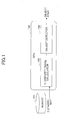
- FIG. 1 is a basic block diagram of a system according to an embodiment of the present invention; the system adopts a method of detecting at least one object on a road.
- the method is fulfilled basically in a CPU 102; of course, it may also be achieved among plural modules independent of each other or connected to each other.
- the system in this embodiment comprises a memory 101 and the CPU 102.
- the CPU 102 includes a V-disparity image calculator 103 and an object detector 104.
- a disparity map (an original disparity map) is stored in the memory 101.
- the disparity map is obtained on the basis of two depth maps of a same scene, simultaneously captured by two depth cameras disposed in parallel.
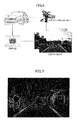
- FIG. 6 illustrates an example of an environment in which a method and a system according to embodiments of the present invention are adopted.
- the two depth cameras disposed in parallel are like the two eyes of a human being, and may capture two depth maps of the same scene (a current scene) in front of them at the same time.
- the two cameras may be the same.
- the captured two depth maps may be directly processed by a processor inside the depth camera set so as to generate a disparity map of the current scene, and then the disparity map may be output to and stored in the memory 101.
- the captured two depth maps may be transmitted to the CPU 102 so as to let the CPU 102 carry out a proper process to obtain a disparity map of the current scene, and then the disparity map is output to and stored in the memory 101.
- FIG. 7 illustrates an example of a disparity map.
- the V-disparity image calculator 103 conducts, based on the disparity map read from the memory 101, a V-disparity calculating process so as to acquire a V-disparity image corresponding to the disparity map.
- the height of the V-disparity image is equal to that of the disparity map, and the width is equal to the maximum disparity value.
- a point p in the V-disparity image may be obtained (here the horizontal coordinate value of p is v, the vertical coordinate value is I, and the strength value is n).
- FIG. 8 illustrates an example of calculating a V-disparity image by the V-disparity image calculator 103 shown in FIG. 1 on the basis of a disparity map.
- a point P of the V-disparity image may be obtained by calculating the number of points having a same gray level in the corresponding line.
- the horizontal coordinate value x stands for the gray value of the point P; that is, the points having a same gray level, in a same line of the disparity map are represented by the point P in the V-disparity image, and the horizontal coordinate value of the point P is the corresponding gray level of the disparity map.
- the vertical coordinate value of the point P corresponds to the same line in the disparity map, including the points having the same gray level.
- the strength value of the point P in the V-disparity image stands for the number of the points having the same gray level, in the same line of the disparity map.
- a point for example, the point P
- a point represents various points in the same line on the road surface in the disparity map.
- a depth value i.e., the gray levels
- a graphic formed by the points representing the road surface must be an oblique line.
- the object detector 104 detects, based on the V-disparity image output from the V-disparity image calculator 103, at least one specific object.
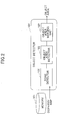
- FIG. 2 is a block diagram of the object detector 104 shown in FIG. 1 .
- the object detector 104 includes a road detector 105, an object area detector 106, and an object area merging unit 107.
- the road detector 105 detects an oblique line in the V-disparity image, corresponding to a road.
- the oblique line corresponding to the road is called a "road line”.
- all of the points corresponding to this point (in the oblique line), in a same line of the disparity map within a range determined on the basis of the horizontal coordinate value of this point in the oblique line, are removed. In this way, finally a sub-disparity map (another original disparity map) excluding the road is obtained.
- FIG. 3 is a block diagram of the road detector 105 shown in FIG. 2 .
- the road detector 105 includes an oblique line detector 108 and a road surface extractor 109.
- the oblique line detector 108 seeks (detects) the oblique line representing the road.
- the Hough transform is utilized for seeking the oblique line in the V-disparity image.
- the sought oblique line is extended so as to intersect with the x-axis and the y-axis, respectively.
- FIG. 9 illustrates an example of seeking an oblique line in a V-disparity image.
- the sought oblique line is extended so as to intersect with the horizontal and vertical axes of the V-disparity image, respectively.
- the road surface extractor 109 recovers (generates), based on the extended oblique line, the points in the disparity map, corresponding to various points on the oblique line. These recovered points are those on the road surface in the disparity map.
- the road surface in the disparity is recovered, by subtracting the road surface corresponding to the sought oblique line from the original disparity map, the road surface may be extracted from the original disparity map.
- the road surface is not entirely vertical to the depth cameras (i.e., for example, in FIG. 7 , the direction of the road surface is not entirely vertical to the bottom side); as a result, an obtained depth value may have an error.
- the oblique line may be divided on the basis of the disparities (i.e., the x-axis coordinate values in the V-disparity image, namely, the gray levels or the depth values of the points in the disparity map, corresponding to the points on the oblique line) so as to more accurately determine the road surface.
- the oblique line is divided into plural sub-line segments on the basis of the x-axis coordinate values in the V-disparity image.
- disparity ranges may be adopted to extract the road surface.
- a distance dc from the depth camera set is greater than 20 meters, then a same disparity value D (its unit is in pixels) is adopted; if the distance dc is equal to or greater than 10 meters and is less than 20 meters, then the disparity range is [D, D-1]; and if the distance dc is less than 10 meters, then the disparity range is [D, D-2].
- the disparity value D may be defined by the following equations (1).
- D f * T / dc + f
- f refers to the focal length of any one of the two depth cameras or the average focal length of the two depth cameras
- T refers to the distance between the two depth cameras (for example, 0 ⁇ 50 cm);
- dc refers to the distance from the depth camera set.
- Disparity Range ⁇ D , D - 2 if D ⁇ 27 D , D - 1 if 15 ⁇ D ⁇ 27 D if D ⁇ 15
- D refers to a disparity value, and its unit is in pixels.
- FIG. 10 illustrates an example of dividing an oblique line in a V-disparity image.
- the road surface extractor 109 extracts the road surface in the disparity map on the basis of the divided sub-line segments. For each point on the oblique line in the V-disparity image, the points corresponding to this point on the oblique line within the disparity range, on a same line in the disparity map may be sought; these kinds of points in the disparity map are the road surface points.
- FIG. 11 illustrates an example of extracting a road surface from a disparity map.
- a road surface disparity map corresponding to the oblique line is obtained;
- a sub-disparity map only including at least one object on the road surface is obtained.
- the road surface extractor 109 After the road surface extraction, the road surface extractor 109 outputs the sub-disparity map including the object into the object area detector 106.
- the object area detector 106 extracts, based on the feature of the specific object in the disparity map, at least one candidate object from the sub-disparity map output from the road surface extractor 109.
- FIG. 4 is a block diagram of the object area detector 106 shown in FIG. 2 .
- the object area detector 106 includes a vertical line detector 110, an object extractor 111, a noise processor 112, and a point clustering processor 113.
- the vertical line detector 110 detects each vertical line in the V-disparity image.
- each vertical line may corresponds to an object.
- continuous points having a same gray level (a same x-axis coordinate value) not equal to zero are sought.
- a line formed by these kinds of continuous points may be a possible object.
- the object extractor 111 seeks (detects), for each vertical line detected and output by the vertical line detector 110, plural points corresponding to this vertical line, in the sub-disparity map output from the road surface extractor 109, and the detected plural points in the sub-disparity map make up a disparity map of an object in the sub-disparity map (also called an "object sub-disparity map"). After that, the object extractor 111 extracts each object sub-disparity map from the sub-disparity map, and outputs it to the noise processor 112.
- FIG. 12 illustrates an example of extracting an object sub-disparity map.
- each object sub-disparity map possibly including an object
- the disparity value of this point is D
- all of the points on a same line in the sub-disparity map, within a disparity range of (D, D+ ⁇ ) are sought, and these points may be those belonging to the object.
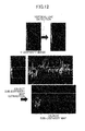
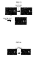
- the noise processor 112 carries out a smoothing process with regard to each object sub-disparity map output from the object extractor 111, and then removes connection points in each object sub-disparity map.
- the smoothing process since it is a well-known technique in the art, its concrete description is omitted. Those people skilled in the art may select a proper smoothing approach according to actual needs.
- a median filtering approach is adopted for performing the smoothing process.
- This kind of smoothing process includes a step of obtaining an odd number of data (gray levels) from a sampling window on the object sub-disparity map, and ranking them; and a step of using the ranked median value to replace the gray levels of all of the points in the sampling window.
- FIG. 13 illustrates an example of carrying out a smoothing process with regard to an object sub-disparity map.
- the point clustering processor 113 conducts a point clustering process with regard to each object sub-disparity map.
- FIG. 14 illustrates an example of performing a point clustering process with regard to an object sub-disparity map.
- the point clustering process is carried out with regard to relatively continuous points.
- the point clustering process is performed on the basis of the distances along the x-axis and y-axis in the object sub-disparity map.
- relatively continuous points are clustered; for example, as for any two points C1 and C2, if their distance along the x-axis is equal to or less than 2, and their distance along the y-axis is also equal to or less than 2, then the two points C1 and C2 belong to a same class C.
- any other point C3 if the distance between C3 and C1 (or C2) along the x-axis is equal to and less than 2, and the distance between C3 and C1 (or C2) along the y-axis is also equal to or less than 2, then the other point C3 belongs to the same class C; otherwise, a new class is generated on the basis of the point C3, and the point C3 is included in the generated new class.
- the point clustering processor 113 outputs the respective rectangular object areas including objects.
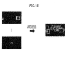
- the object area merging unit 107 conducts a merging process with regard to the respective rectangle object areas output by the point clustering processor 113 so as to output at least one merged object area.
- an overlap area value and a disparity distance are employed to merge two rectangular object areas.
- there are two rectangular object areas i.e., two rectangles (x0, y0, w0, h0) and (x1, y1, w1, h1).
- (x0, y0) and (x1, y1) refer to the coordinate values of the top-left corner points of the two rectangles, respectively; w0 and w1 refer to the width values of the two rectangles, respectively; and h0 and h1 refer to the height values of two rectangles, respectively. If the absolute value of the difference vale between two distances from the two rectangles to the corresponding two depth cameras is less than a first predetermined value (for example, 3 meters; also 0.5, 1, 1.5, or 2 meters), then the overlap area value of the two rectangles needs to be calculated.
- a first predetermined value for example, 3 meters; also 0.5, 1, 1.5, or 2 meters
- the ratio of the overlap area value of the two rectangles to the area value of the smaller one of the two rectangles is greater than a second predetermined value (for example, 0.65, 0.7, or 0.75), then these two rectangles need to be merged. That is, the merged object area is (min(x0, x01, min(y0, y1), max(w0, w1), max(h0, h1)) in which min() refers to calculating the minimum value, and max() refers to calculating the maximum value.
- FIG. 15 illustrates an example of merging rectangular object areas.
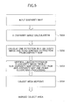
- FIG. 5 is a flowchart of the method in this embodiment.
- the V-disparity image calculator 103 carries out, based on a disparity map (an original disparity map) read from the memory 101, a V-disparity calculation process so as to obtain a V-disparity image. Then, in STEP S202, the road detector 105 in the object detector 104 detects a road in the V-disparity image, and subtracts a disparity map corresponding to the road detected in the V-disparity image from the original disparity map so as to obtain a sub-disparity map (another original sub-disparity map excluding the road).
- a disparity map an original disparity map
- the object area detector 106 in the object detector 104 extracts, based on a feature of at least one specific object in the original disparity map, at least one object candidate from the sub-disparity map output from the road surface extractor 109 in the road detector 105, and then performs a point clustering process.
- the object merging unit 107 conducts a merging process with regard to rectangular object areas output from the object area detector 106, and outputs at least one emerged object area.
- the above method may be executed in a computer (a processor), or may be distributedly executed among plural computers.
- a program able to achieve the method may be stored in a non-transitory computer (machine) readable medium, or may be transmitted to a remote computer for purpose of execution.
Landscapes
- Engineering & Computer Science (AREA)
- Multimedia (AREA)
- Physics & Mathematics (AREA)
- General Physics & Mathematics (AREA)
- Theoretical Computer Science (AREA)
- Signal Processing (AREA)
- Computer Vision & Pattern Recognition (AREA)
- Image Processing (AREA)
- Image Analysis (AREA)
- Traffic Control Systems (AREA)
- Closed-Circuit Television Systems (AREA)
Applications Claiming Priority (1)
| Application Number | Priority Date | Filing Date | Title |
|---|---|---|---|
| CN201110369183.0A CN103123722B (zh) | 2011-11-18 | 2011-11-18 | 道路对象检测方法和系统 |
Publications (3)
| Publication Number | Publication Date |
|---|---|
| EP2728546A2 true EP2728546A2 (de) | 2014-05-07 |
| EP2728546A3 EP2728546A3 (de) | 2015-04-08 |
| EP2728546B1 EP2728546B1 (de) | 2020-02-12 |
Family
ID=47191599
Family Applications (1)
| Application Number | Title | Priority Date | Filing Date |
|---|---|---|---|
| EP12192685.1A Active EP2728546B1 (de) | 2011-11-18 | 2012-11-14 | Verfahren und System zum Erfassen eines Objekts auf einer Straße |
Country Status (4)
| Country | Link |
|---|---|
| US (1) | US8923605B2 (de) |
| EP (1) | EP2728546B1 (de) |
| JP (1) | JP2013109760A (de) |
| CN (1) | CN103123722B (de) |
Cited By (1)
| Publication number | Priority date | Publication date | Assignee | Title |
|---|---|---|---|---|
| AT518438A1 (de) * | 2016-03-24 | 2017-10-15 | Pas Gmbh | Verfahren zur Selbstlokalisierung von Fahrzeugen |
Families Citing this family (43)
| Publication number | Priority date | Publication date | Assignee | Title |
|---|---|---|---|---|
| US9113043B1 (en) * | 2011-10-24 | 2015-08-18 | Disney Enterprises, Inc. | Multi-perspective stereoscopy from light fields |
| CN103164851B (zh) * | 2011-12-09 | 2016-04-20 | 株式会社理光 | 道路分割物检测方法和装置 |
| CN104217208B (zh) * | 2013-06-03 | 2018-01-16 | 株式会社理光 | 目标检测方法和装置 |
| CN104252707B (zh) * | 2013-06-27 | 2017-06-06 | 株式会社理光 | 对象检测方法和装置 |
| KR101782496B1 (ko) * | 2013-08-21 | 2017-09-27 | 주식회사 만도 | 후측방 경보 시스템 및 그의 경보 제어 방법 |
| TWI508526B (zh) * | 2013-10-01 | 2015-11-11 | Wistron Corp | 產生視角平移影像之方法及其可攜式電子設備 |
| CN103679707A (zh) * | 2013-11-26 | 2014-03-26 | 西安交通大学 | 基于双目相机视差图的道路障碍物检测系统及检测方法 |
| CN103712602A (zh) * | 2013-12-09 | 2014-04-09 | 广西科技大学 | 一种基于双目视觉道路障碍物自动检测的方法 |
| KR101551026B1 (ko) * | 2013-12-24 | 2015-09-07 | 현대자동차주식회사 | 차량 검출 방법 |
| US9446765B2 (en) | 2014-01-30 | 2016-09-20 | Mobileye Vision Technologies Ltd. | Systems and methods for identifying relevant traffic lights |
| CN104902261B (zh) * | 2014-03-06 | 2017-08-08 | 株式会社日立制作所 | 用于低清晰度视频流中的路面识别的装置和方法 |
| JP6087858B2 (ja) * | 2014-03-24 | 2017-03-01 | 株式会社日本自動車部品総合研究所 | 走行区画線認識装置及び走行区画線認識プログラム |
| JP6648411B2 (ja) * | 2014-05-19 | 2020-02-14 | 株式会社リコー | 処理装置、処理システム、処理プログラム及び処理方法 |
| JP6550881B2 (ja) * | 2014-07-14 | 2019-07-31 | 株式会社リコー | 立体物検出装置、立体物検出方法、立体物検出プログラム、及び移動体機器制御システム |
| WO2016044296A1 (en) | 2014-09-15 | 2016-03-24 | Second Sight Medical Products, Inc. | Method and system for detecting obstacles for a visual prosthesis |
| CN104318206B (zh) * | 2014-09-30 | 2017-09-29 | 东软集团股份有限公司 | 一种障碍物检测方法和装置 |
| BE1023147B1 (nl) * | 2015-07-03 | 2016-12-01 | Cnh Industrial Belgium Nv | Controller voor een werkvoertuig |
| US9761000B2 (en) * | 2015-09-18 | 2017-09-12 | Qualcomm Incorporated | Systems and methods for non-obstacle area detection |
| EP3385904A4 (de) | 2015-11-30 | 2018-12-19 | Ricoh Company, Ltd. | Bildverarbeitungsvorrichtung, objekterkennungsvorrichtung, vorrichtungssteuerungssystem, bildverarbeitungsverfahren und programm |
| CN105740802A (zh) * | 2016-01-28 | 2016-07-06 | 北京中科慧眼科技有限公司 | 基于视差图的障碍物检测方法和装置及汽车驾驶辅助系统 |
| JP6690267B2 (ja) * | 2016-02-03 | 2020-04-28 | トヨタ自動車株式会社 | 車両用立体物検出装置 |
| US10402671B2 (en) * | 2016-03-28 | 2019-09-03 | General Dynamics Mission Systems, Inc. | System and methods for automatic solar panel recognition and defect detection using infrared imaging |
| CN106023180A (zh) * | 2016-05-17 | 2016-10-12 | 李迎春 | 一种非结构化道路rgb熵分割方法 |
| MY205598A (en) * | 2016-11-25 | 2024-10-29 | Ricoh Co Ltd | Information processing device, imaging device, equipment control system, mobile object, information processing method, and computer-readable recording medium |
| JP6794243B2 (ja) * | 2016-12-19 | 2020-12-02 | 日立オートモティブシステムズ株式会社 | 物体検出装置 |
| WO2018119744A1 (zh) * | 2016-12-28 | 2018-07-05 | 深圳前海达闼云端智能科技有限公司 | 一种虚警障碍物检测方法及装置 |
| US10296812B2 (en) * | 2017-01-04 | 2019-05-21 | Qualcomm Incorporated | Systems and methods for mapping based on multi-journey data |
| CN109426760A (zh) * | 2017-08-22 | 2019-03-05 | 聚晶半导体股份有限公司 | 一种道路图像处理方法与道路图像处理装置 |
| CN109472180A (zh) * | 2017-09-07 | 2019-03-15 | 聚晶半导体股份有限公司 | 道路图像处理方法与道路图像处理装置 |
| CN107977649B (zh) * | 2017-12-21 | 2020-02-07 | 海信集团有限公司 | 一种障碍物识别方法、装置及终端 |
| CN107977654B (zh) * | 2017-12-25 | 2020-07-31 | 海信集团有限公司 | 一种道路区域检测方法、装置及终端 |
| CN110044256B (zh) * | 2018-01-16 | 2022-02-08 | 爱信精机株式会社 | 自车位置估计装置 |
| CN108596012B (zh) * | 2018-01-19 | 2022-07-15 | 海信集团有限公司 | 一种障碍物框合并方法、装置及终端 |
| KR102586966B1 (ko) * | 2018-08-01 | 2023-10-10 | 한화에어로스페이스 주식회사 | 실내-지도 생성 시스템 및 실내-탐사 로봇 |
| CN110262521A (zh) * | 2019-07-24 | 2019-09-20 | 北京智行者科技有限公司 | 一种自动驾驶控制方法 |
| KR20210147405A (ko) * | 2020-05-28 | 2021-12-07 | 삼성전자주식회사 | 객체 인식을 수행하는 전자 장치 및 이의 동작 방법 |
| CN111709938B (zh) * | 2020-06-18 | 2023-07-07 | 武汉唯理科技有限公司 | 一种基于深度图的路面缺陷及抛洒物检测方法 |
| JP7828741B2 (ja) * | 2021-10-20 | 2026-03-12 | Astemo株式会社 | 画像処理装置 |
| CN113963163A (zh) * | 2021-12-21 | 2022-01-21 | 北京中科慧眼科技有限公司 | 一种基于图像分割的障碍物提取方法、系统和智能终端 |
| US12482137B2 (en) | 2022-04-29 | 2025-11-25 | Nvidia Corporation | Detecting hazards based on disparity maps using computer vision for autonomous machine systems and applications |
| US12676008B2 (en) * | 2022-04-29 | 2026-07-07 | Nvidia Corporation | Detecting hazards based on disparity maps using machine learning for autonomous machine systems and applications |
| CN116805332B (zh) * | 2023-02-27 | 2026-02-03 | 中冶华天南京工程技术有限公司 | 一种基于霍夫变换的型钢姿态判别方法 |
| CN119130985B (zh) * | 2024-09-09 | 2025-04-29 | 元橡科技(北京)有限公司 | 地面视差误检的判断方法、装置、系统及存储介质 |
Citations (1)
| Publication number | Priority date | Publication date | Assignee | Title |
|---|---|---|---|---|
| US7729512B2 (en) | 2005-03-23 | 2010-06-01 | Kabushiki Kaisha Toshiba | Stereo image processing to detect moving objects |
Family Cites Families (13)
| Publication number | Priority date | Publication date | Assignee | Title |
|---|---|---|---|---|
| US6701005B1 (en) | 2000-04-29 | 2004-03-02 | Cognex Corporation | Method and apparatus for three-dimensional object segmentation |
| JP4612635B2 (ja) | 2003-10-09 | 2011-01-12 | 本田技研工業株式会社 | 低照度の深度に適応可能なコンピュータ視覚を用いた移動物体検出 |
| US7486803B2 (en) | 2003-12-15 | 2009-02-03 | Sarnoff Corporation | Method and apparatus for object tracking prior to imminent collision detection |
| JP4534571B2 (ja) * | 2004-04-22 | 2010-09-01 | 三菱電機株式会社 | 顔検出装置 |
| EP2765533A1 (de) * | 2004-07-26 | 2014-08-13 | Automotive Systems Laboratory, Inc. | Schutzsystem für gefährdete Straßenbenutzer |
| JP2006053694A (ja) * | 2004-08-10 | 2006-02-23 | Riyuukoku Univ | 空間シミュレータ、空間シミュレート方法、空間シミュレートプログラム、記録媒体 |
| FR2898986B1 (fr) * | 2006-03-24 | 2008-05-23 | Inrets | Detection d'obstacle |
| WO2007124502A2 (en) * | 2006-04-21 | 2007-11-01 | Sarnoff Corporation | Apparatus and method for object detection and tracking and roadway awareness using stereo cameras |
| JP2008165595A (ja) * | 2006-12-28 | 2008-07-17 | Sumitomo Electric Ind Ltd | 障害物検出方法、障害物検出装置、障害物検出システム |
| CN101436253B (zh) * | 2007-11-14 | 2012-04-25 | 东软集团股份有限公司 | 一种用于验证车辆感兴趣区域的方法和装置 |
| CN101608924B (zh) * | 2009-05-20 | 2011-09-14 | 电子科技大学 | 一种基于灰度估计和级联霍夫变换的车道线检测方法 |
| US8633810B2 (en) * | 2009-11-19 | 2014-01-21 | Robert Bosch Gmbh | Rear-view multi-functional camera system |
| KR101163042B1 (ko) * | 2009-11-26 | 2012-07-05 | 재단법인대구경북과학기술원 | 차량 검출 장치 및 방법 |
-
2011
- 2011-11-18 CN CN201110369183.0A patent/CN103123722B/zh active Active
-
2012
- 2012-11-09 US US13/673,199 patent/US8923605B2/en active Active
- 2012-11-14 EP EP12192685.1A patent/EP2728546B1/de active Active
- 2012-11-15 JP JP2012250971A patent/JP2013109760A/ja active Pending
Patent Citations (1)
| Publication number | Priority date | Publication date | Assignee | Title |
|---|---|---|---|---|
| US7729512B2 (en) | 2005-03-23 | 2010-06-01 | Kabushiki Kaisha Toshiba | Stereo image processing to detect moving objects |
Non-Patent Citations (1)
| Title |
|---|
| VISIGRAPH, 2010 |
Cited By (1)
| Publication number | Priority date | Publication date | Assignee | Title |
|---|---|---|---|---|
| AT518438A1 (de) * | 2016-03-24 | 2017-10-15 | Pas Gmbh | Verfahren zur Selbstlokalisierung von Fahrzeugen |
Also Published As
| Publication number | Publication date |
|---|---|
| CN103123722A (zh) | 2013-05-29 |
| US8923605B2 (en) | 2014-12-30 |
| EP2728546A3 (de) | 2015-04-08 |
| US20130128001A1 (en) | 2013-05-23 |
| CN103123722B (zh) | 2016-04-27 |
| JP2013109760A (ja) | 2013-06-06 |
| EP2728546B1 (de) | 2020-02-12 |
Similar Documents
| Publication | Publication Date | Title |
|---|---|---|
| US8923605B2 (en) | Method and system for detecting object on a road | |
| US9607227B2 (en) | Boundary detection apparatus and boundary detection method | |
| Wu et al. | Lane-mark extraction for automobiles under complex conditions | |
| KR101517181B1 (ko) | 차선 이탈 경보 시스템 및 방법 | |
| EP2779025B1 (de) | Verfahren und Vorrichtung zur Erkennung einer Straßenkante | |
| EP3545464B1 (de) | Informationsverarbeitungsvorrichtung, bildgebungsvorrichtung, ausrüstungssteuerungssystem, bewegliches objekt, informationsverarbeitungsverfahren und computerlesbares aufzeichnungsmedium | |
| EP2928178B1 (de) | Bordsteuerungsvorrichtung | |
| EP3410416B1 (de) | Bildverarbeitungsvorrichtung, bildgebungsvorrichtung, steuerungssystem für mobilitätsvorrichtung, bildverarbeitungsverfahren und programm | |
| Labayrade et al. | In-vehicle obstacles detection and characterization by stereovision | |
| EP2720193A2 (de) | Verfahren und System zur Erkennung einer unebenen Straßenoberfläche | |
| CN108243623A (zh) | 基于双目立体视觉的汽车防碰撞预警方法和系统 | |
| KR101285106B1 (ko) | 영상 데이터 융합 기반의 장애물체 검출 방법 및 장치 | |
| JP6583527B2 (ja) | 画像処理装置、撮像装置、移動体機器制御システム、画像処理方法、及びプログラム | |
| CN105206109A (zh) | 一种基于红外ccd的车辆雾天识别预警系统及方法 | |
| EP2677462B1 (de) | Verfahren und Vorrichtung zur Segmentierung eines Objektbereichs | |
| JPWO2017145634A1 (ja) | 画像処理装置、撮像装置、移動体機器制御システム、画像処理方法、及びプログラム | |
| EP3432265A1 (de) | Bildverarbeitungsvorrichtung, vorrichtungssteuerungssystem, bildaufnahmevorrichtung, bildverarbeitungsverfahren und programm | |
| Yiruo et al. | Complex ground plane detection based on v-disparity map in off-road environment | |
| KR101699014B1 (ko) | 스테레오 카메라를 이용한 객체 검출 방법 및 장치 | |
| KR20180063524A (ko) | 가상 차선을 이용한 전방 차량 위험도 감지 방법 및 장치 | |
| CN104915642A (zh) | 前方车辆测距方法及装置 | |
| Petrovai et al. | A stereovision based approach for detecting and tracking lane and forward obstacles on mobile devices | |
| KR101998584B1 (ko) | 차선 검출 장치 및 차선 검출 방법 | |
| KR101205565B1 (ko) | 영상을 이용한 전후방 차량 검출 방법 | |
| Peláez et al. | Road detection with thermal cameras through 3D information |
Legal Events
| Date | Code | Title | Description |
|---|---|---|---|
| PUAI | Public reference made under article 153(3) epc to a published international application that has entered the european phase |
Free format text: ORIGINAL CODE: 0009012 |
|
| 17P | Request for examination filed |
Effective date: 20121114 |
|
| AK | Designated contracting states |
Kind code of ref document: A2 Designated state(s): AL AT BE BG CH CY CZ DE DK EE ES FI FR GB GR HR HU IE IS IT LI LT LU LV MC MK MT NL NO PL PT RO RS SE SI SK SM TR |
|
| AX | Request for extension of the european patent |
Extension state: BA ME |
|
| PUAL | Search report despatched |
Free format text: ORIGINAL CODE: 0009013 |
|
| AK | Designated contracting states |
Kind code of ref document: A3 Designated state(s): AL AT BE BG CH CY CZ DE DK EE ES FI FR GB GR HR HU IE IS IT LI LT LU LV MC MK MT NL NO PL PT RO RS SE SI SK SM TR |
|
| AX | Request for extension of the european patent |
Extension state: BA ME |
|
| RIC1 | Information provided on ipc code assigned before grant |
Ipc: G06K 9/00 20060101ALI20150303BHEP Ipc: G06T 7/00 20060101AFI20150303BHEP |
|
| STAA | Information on the status of an ep patent application or granted ep patent |
Free format text: STATUS: EXAMINATION IS IN PROGRESS |
|
| 17Q | First examination report despatched |
Effective date: 20171121 |
|
| REG | Reference to a national code |
Ref country code: DE Ref legal event code: R079 Ref document number: 602012067667 Country of ref document: DE Free format text: PREVIOUS MAIN CLASS: G06T0007000000 Ipc: G06T0007730000 |
|
| RIC1 | Information provided on ipc code assigned before grant |
Ipc: G06T 7/73 20170101AFI20190917BHEP Ipc: G06K 9/00 20060101ALI20190917BHEP |
|
| GRAP | Despatch of communication of intention to grant a patent |
Free format text: ORIGINAL CODE: EPIDOSNIGR1 |
|
| STAA | Information on the status of an ep patent application or granted ep patent |
Free format text: STATUS: GRANT OF PATENT IS INTENDED |
|
| INTG | Intention to grant announced |
Effective date: 20191029 |
|
| GRAS | Grant fee paid |
Free format text: ORIGINAL CODE: EPIDOSNIGR3 |
|
| GRAA | (expected) grant |
Free format text: ORIGINAL CODE: 0009210 |
|
| STAA | Information on the status of an ep patent application or granted ep patent |
Free format text: STATUS: THE PATENT HAS BEEN GRANTED |
|
| RIN1 | Information on inventor provided before grant (corrected) |
Inventor name: LU, YAOJIE Inventor name: YOU, GANMEI Inventor name: ZHENG, JICHUAN |
|
| AK | Designated contracting states |
Kind code of ref document: B1 Designated state(s): AL AT BE BG CH CY CZ DE DK EE ES FI FR GB GR HR HU IE IS IT LI LT LU LV MC MK MT NL NO PL PT RO RS SE SI SK SM TR |
|
| REG | Reference to a national code |
Ref country code: GB Ref legal event code: FG4D |
|
| REG | Reference to a national code |
Ref country code: CH Ref legal event code: EP |
|
| REG | Reference to a national code |
Ref country code: AT Ref legal event code: REF Ref document number: 1233128 Country of ref document: AT Kind code of ref document: T Effective date: 20200215 |
|
| REG | Reference to a national code |
Ref country code: DE Ref legal event code: R096 Ref document number: 602012067667 Country of ref document: DE |
|
| REG | Reference to a national code |
Ref country code: IE Ref legal event code: FG4D |
|
| PG25 | Lapsed in a contracting state [announced via postgrant information from national office to epo] |
Ref country code: RS Free format text: LAPSE BECAUSE OF FAILURE TO SUBMIT A TRANSLATION OF THE DESCRIPTION OR TO PAY THE FEE WITHIN THE PRESCRIBED TIME-LIMIT Effective date: 20200212 Ref country code: NO Free format text: LAPSE BECAUSE OF FAILURE TO SUBMIT A TRANSLATION OF THE DESCRIPTION OR TO PAY THE FEE WITHIN THE PRESCRIBED TIME-LIMIT Effective date: 20200512 Ref country code: FI Free format text: LAPSE BECAUSE OF FAILURE TO SUBMIT A TRANSLATION OF THE DESCRIPTION OR TO PAY THE FEE WITHIN THE PRESCRIBED TIME-LIMIT Effective date: 20200212 |
|
| REG | Reference to a national code |
Ref country code: LT Ref legal event code: MG4D |
|
| REG | Reference to a national code |
Ref country code: NL Ref legal event code: MP Effective date: 20200212 |
|
| PG25 | Lapsed in a contracting state [announced via postgrant information from national office to epo] |
Ref country code: IS Free format text: LAPSE BECAUSE OF FAILURE TO SUBMIT A TRANSLATION OF THE DESCRIPTION OR TO PAY THE FEE WITHIN THE PRESCRIBED TIME-LIMIT Effective date: 20200612 Ref country code: BG Free format text: LAPSE BECAUSE OF FAILURE TO SUBMIT A TRANSLATION OF THE DESCRIPTION OR TO PAY THE FEE WITHIN THE PRESCRIBED TIME-LIMIT Effective date: 20200512 Ref country code: SE Free format text: LAPSE BECAUSE OF FAILURE TO SUBMIT A TRANSLATION OF THE DESCRIPTION OR TO PAY THE FEE WITHIN THE PRESCRIBED TIME-LIMIT Effective date: 20200212 Ref country code: LV Free format text: LAPSE BECAUSE OF FAILURE TO SUBMIT A TRANSLATION OF THE DESCRIPTION OR TO PAY THE FEE WITHIN THE PRESCRIBED TIME-LIMIT Effective date: 20200212 Ref country code: GR Free format text: LAPSE BECAUSE OF FAILURE TO SUBMIT A TRANSLATION OF THE DESCRIPTION OR TO PAY THE FEE WITHIN THE PRESCRIBED TIME-LIMIT Effective date: 20200513 Ref country code: HR Free format text: LAPSE BECAUSE OF FAILURE TO SUBMIT A TRANSLATION OF THE DESCRIPTION OR TO PAY THE FEE WITHIN THE PRESCRIBED TIME-LIMIT Effective date: 20200212 |
|
| PG25 | Lapsed in a contracting state [announced via postgrant information from national office to epo] |
Ref country code: NL Free format text: LAPSE BECAUSE OF FAILURE TO SUBMIT A TRANSLATION OF THE DESCRIPTION OR TO PAY THE FEE WITHIN THE PRESCRIBED TIME-LIMIT Effective date: 20200212 |
|
| PG25 | Lapsed in a contracting state [announced via postgrant information from national office to epo] |
Ref country code: LT Free format text: LAPSE BECAUSE OF FAILURE TO SUBMIT A TRANSLATION OF THE DESCRIPTION OR TO PAY THE FEE WITHIN THE PRESCRIBED TIME-LIMIT Effective date: 20200212 Ref country code: DK Free format text: LAPSE BECAUSE OF FAILURE TO SUBMIT A TRANSLATION OF THE DESCRIPTION OR TO PAY THE FEE WITHIN THE PRESCRIBED TIME-LIMIT Effective date: 20200212 Ref country code: EE Free format text: LAPSE BECAUSE OF FAILURE TO SUBMIT A TRANSLATION OF THE DESCRIPTION OR TO PAY THE FEE WITHIN THE PRESCRIBED TIME-LIMIT Effective date: 20200212 Ref country code: SM Free format text: LAPSE BECAUSE OF FAILURE TO SUBMIT A TRANSLATION OF THE DESCRIPTION OR TO PAY THE FEE WITHIN THE PRESCRIBED TIME-LIMIT Effective date: 20200212 Ref country code: SK Free format text: LAPSE BECAUSE OF FAILURE TO SUBMIT A TRANSLATION OF THE DESCRIPTION OR TO PAY THE FEE WITHIN THE PRESCRIBED TIME-LIMIT Effective date: 20200212 Ref country code: ES Free format text: LAPSE BECAUSE OF FAILURE TO SUBMIT A TRANSLATION OF THE DESCRIPTION OR TO PAY THE FEE WITHIN THE PRESCRIBED TIME-LIMIT Effective date: 20200212 Ref country code: PT Free format text: LAPSE BECAUSE OF FAILURE TO SUBMIT A TRANSLATION OF THE DESCRIPTION OR TO PAY THE FEE WITHIN THE PRESCRIBED TIME-LIMIT Effective date: 20200705 Ref country code: RO Free format text: LAPSE BECAUSE OF FAILURE TO SUBMIT A TRANSLATION OF THE DESCRIPTION OR TO PAY THE FEE WITHIN THE PRESCRIBED TIME-LIMIT Effective date: 20200212 Ref country code: CZ Free format text: LAPSE BECAUSE OF FAILURE TO SUBMIT A TRANSLATION OF THE DESCRIPTION OR TO PAY THE FEE WITHIN THE PRESCRIBED TIME-LIMIT Effective date: 20200212 |
|
| REG | Reference to a national code |
Ref country code: DE Ref legal event code: R097 Ref document number: 602012067667 Country of ref document: DE |
|
| REG | Reference to a national code |
Ref country code: AT Ref legal event code: MK05 Ref document number: 1233128 Country of ref document: AT Kind code of ref document: T Effective date: 20200212 |
|
| PLBE | No opposition filed within time limit |
Free format text: ORIGINAL CODE: 0009261 |
|
| STAA | Information on the status of an ep patent application or granted ep patent |
Free format text: STATUS: NO OPPOSITION FILED WITHIN TIME LIMIT |
|
| 26N | No opposition filed |
Effective date: 20201113 |
|
| PG25 | Lapsed in a contracting state [announced via postgrant information from national office to epo] |
Ref country code: IT Free format text: LAPSE BECAUSE OF FAILURE TO SUBMIT A TRANSLATION OF THE DESCRIPTION OR TO PAY THE FEE WITHIN THE PRESCRIBED TIME-LIMIT Effective date: 20200212 Ref country code: AT Free format text: LAPSE BECAUSE OF FAILURE TO SUBMIT A TRANSLATION OF THE DESCRIPTION OR TO PAY THE FEE WITHIN THE PRESCRIBED TIME-LIMIT Effective date: 20200212 |
|
| PG25 | Lapsed in a contracting state [announced via postgrant information from national office to epo] |
Ref country code: SI Free format text: LAPSE BECAUSE OF FAILURE TO SUBMIT A TRANSLATION OF THE DESCRIPTION OR TO PAY THE FEE WITHIN THE PRESCRIBED TIME-LIMIT Effective date: 20200212 Ref country code: PL Free format text: LAPSE BECAUSE OF FAILURE TO SUBMIT A TRANSLATION OF THE DESCRIPTION OR TO PAY THE FEE WITHIN THE PRESCRIBED TIME-LIMIT Effective date: 20200212 |
|
| PG25 | Lapsed in a contracting state [announced via postgrant information from national office to epo] |
Ref country code: MC Free format text: LAPSE BECAUSE OF FAILURE TO SUBMIT A TRANSLATION OF THE DESCRIPTION OR TO PAY THE FEE WITHIN THE PRESCRIBED TIME-LIMIT Effective date: 20200212 |
|
| REG | Reference to a national code |
Ref country code: CH Ref legal event code: PL |
|
| PG25 | Lapsed in a contracting state [announced via postgrant information from national office to epo] |
Ref country code: LU Free format text: LAPSE BECAUSE OF NON-PAYMENT OF DUE FEES Effective date: 20201114 |
|
| REG | Reference to a national code |
Ref country code: BE Ref legal event code: MM Effective date: 20201130 |
|
| PG25 | Lapsed in a contracting state [announced via postgrant information from national office to epo] |
Ref country code: CH Free format text: LAPSE BECAUSE OF NON-PAYMENT OF DUE FEES Effective date: 20201130 Ref country code: LI Free format text: LAPSE BECAUSE OF NON-PAYMENT OF DUE FEES Effective date: 20201130 |
|
| PG25 | Lapsed in a contracting state [announced via postgrant information from national office to epo] |
Ref country code: IE Free format text: LAPSE BECAUSE OF NON-PAYMENT OF DUE FEES Effective date: 20201114 |
|
| PG25 | Lapsed in a contracting state [announced via postgrant information from national office to epo] |
Ref country code: TR Free format text: LAPSE BECAUSE OF FAILURE TO SUBMIT A TRANSLATION OF THE DESCRIPTION OR TO PAY THE FEE WITHIN THE PRESCRIBED TIME-LIMIT Effective date: 20200212 Ref country code: MT Free format text: LAPSE BECAUSE OF FAILURE TO SUBMIT A TRANSLATION OF THE DESCRIPTION OR TO PAY THE FEE WITHIN THE PRESCRIBED TIME-LIMIT Effective date: 20200212 Ref country code: CY Free format text: LAPSE BECAUSE OF FAILURE TO SUBMIT A TRANSLATION OF THE DESCRIPTION OR TO PAY THE FEE WITHIN THE PRESCRIBED TIME-LIMIT Effective date: 20200212 |
|
| PG25 | Lapsed in a contracting state [announced via postgrant information from national office to epo] |
Ref country code: MK Free format text: LAPSE BECAUSE OF FAILURE TO SUBMIT A TRANSLATION OF THE DESCRIPTION OR TO PAY THE FEE WITHIN THE PRESCRIBED TIME-LIMIT Effective date: 20200212 Ref country code: AL Free format text: LAPSE BECAUSE OF FAILURE TO SUBMIT A TRANSLATION OF THE DESCRIPTION OR TO PAY THE FEE WITHIN THE PRESCRIBED TIME-LIMIT Effective date: 20200212 |
|
| PG25 | Lapsed in a contracting state [announced via postgrant information from national office to epo] |
Ref country code: BE Free format text: LAPSE BECAUSE OF NON-PAYMENT OF DUE FEES Effective date: 20201130 |
|
| P01 | Opt-out of the competence of the unified patent court (upc) registered |
Effective date: 20230522 |
|
| PGFP | Annual fee paid to national office [announced via postgrant information from national office to epo] |
Ref country code: DE Payment date: 20241121 Year of fee payment: 13 |
|
| PGFP | Annual fee paid to national office [announced via postgrant information from national office to epo] |
Ref country code: GB Payment date: 20241120 Year of fee payment: 13 |
|
| PGFP | Annual fee paid to national office [announced via postgrant information from national office to epo] |
Ref country code: FR Payment date: 20241128 Year of fee payment: 13 |
|
| REG | Reference to a national code |
Ref country code: DE Ref legal event code: R119 Ref document number: 602012067667 Country of ref document: DE |