EP2728657A1 - Système de pile à combustible - Google Patents
Système de pile à combustible Download PDFInfo
- Publication number
- EP2728657A1 EP2728657A1 EP12191089.7A EP12191089A EP2728657A1 EP 2728657 A1 EP2728657 A1 EP 2728657A1 EP 12191089 A EP12191089 A EP 12191089A EP 2728657 A1 EP2728657 A1 EP 2728657A1
- Authority
- EP
- European Patent Office
- Prior art keywords
- fuel cell
- layer
- fuel
- supply
- cell system
- Prior art date
- Legal status (The legal status is an assumption and is not a legal conclusion. Google has not performed a legal analysis and makes no representation as to the accuracy of the status listed.)
- Withdrawn
Links
- 239000000446 fuel Substances 0.000 title claims abstract description 213
- 239000000376 reactant Substances 0.000 claims abstract description 57
- 239000003792 electrolyte Substances 0.000 claims description 38
- 239000012528 membrane Substances 0.000 claims description 32
- 238000000034 method Methods 0.000 claims description 17
- 239000007800 oxidant agent Substances 0.000 description 11
- 238000006243 chemical reaction Methods 0.000 description 7
- 150000002500 ions Chemical class 0.000 description 4
- VNWKTOKETHGBQD-UHFFFAOYSA-N methane Chemical compound C VNWKTOKETHGBQD-UHFFFAOYSA-N 0.000 description 4
- OKKJLVBELUTLKV-UHFFFAOYSA-N Methanol Chemical compound OC OKKJLVBELUTLKV-UHFFFAOYSA-N 0.000 description 3
- QVGXLLKOCUKJST-UHFFFAOYSA-N atomic oxygen Chemical compound [O] QVGXLLKOCUKJST-UHFFFAOYSA-N 0.000 description 3
- 238000001816 cooling Methods 0.000 description 3
- 229910052739 hydrogen Inorganic materials 0.000 description 3
- 239000001257 hydrogen Substances 0.000 description 3
- 230000001590 oxidative effect Effects 0.000 description 3
- 229910052760 oxygen Inorganic materials 0.000 description 3
- 239000001301 oxygen Substances 0.000 description 3
- XLYOFNOQVPJJNP-UHFFFAOYSA-N water Substances O XLYOFNOQVPJJNP-UHFFFAOYSA-N 0.000 description 3
- CURLTUGMZLYLDI-UHFFFAOYSA-N Carbon dioxide Chemical compound O=C=O CURLTUGMZLYLDI-UHFFFAOYSA-N 0.000 description 2
- 239000003054 catalyst Substances 0.000 description 2
- 230000005611 electricity Effects 0.000 description 2
- 150000002431 hydrogen Chemical class 0.000 description 2
- 239000003345 natural gas Substances 0.000 description 2
- 239000000126 substance Substances 0.000 description 2
- 238000010792 warming Methods 0.000 description 2
- RYGMFSIKBFXOCR-UHFFFAOYSA-N Copper Chemical compound [Cu] RYGMFSIKBFXOCR-UHFFFAOYSA-N 0.000 description 1
- UFHFLCQGNIYNRP-UHFFFAOYSA-N Hydrogen Chemical compound [H][H] UFHFLCQGNIYNRP-UHFFFAOYSA-N 0.000 description 1
- 150000001298 alcohols Chemical class 0.000 description 1
- WYTGDNHDOZPMIW-RCBQFDQVSA-N alstonine Natural products C1=CC2=C3C=CC=CC3=NC2=C2N1C[C@H]1[C@H](C)OC=C(C(=O)OC)[C@H]1C2 WYTGDNHDOZPMIW-RCBQFDQVSA-N 0.000 description 1
- 229910002092 carbon dioxide Inorganic materials 0.000 description 1
- 239000001569 carbon dioxide Substances 0.000 description 1
- 229910052729 chemical element Inorganic materials 0.000 description 1
- 239000003153 chemical reaction reagent Substances 0.000 description 1
- 229910052802 copper Inorganic materials 0.000 description 1
- 239000010949 copper Substances 0.000 description 1
- 230000003247 decreasing effect Effects 0.000 description 1
- 230000001419 dependent effect Effects 0.000 description 1
- 229930195733 hydrocarbon Natural products 0.000 description 1
- 150000002430 hydrocarbons Chemical class 0.000 description 1
- 239000000463 material Substances 0.000 description 1
- 239000002184 metal Substances 0.000 description 1
- 229910052751 metal Inorganic materials 0.000 description 1
- 238000011017 operating method Methods 0.000 description 1
- 239000004033 plastic Substances 0.000 description 1
- 229920003023 plastic Polymers 0.000 description 1
- 238000005086 pumping Methods 0.000 description 1
- 238000011946 reduction process Methods 0.000 description 1
- 239000004065 semiconductor Substances 0.000 description 1
- 230000001131 transforming effect Effects 0.000 description 1
Images


Classifications
-
- H—ELECTRICITY
- H01—ELECTRIC ELEMENTS
- H01M—PROCESSES OR MEANS, e.g. BATTERIES, FOR THE DIRECT CONVERSION OF CHEMICAL ENERGY INTO ELECTRICAL ENERGY
- H01M8/00—Fuel cells; Manufacture thereof
- H01M8/24—Grouping of fuel cells, e.g. stacking of fuel cells
- H01M8/2465—Details of groupings of fuel cells
- H01M8/2484—Details of groupings of fuel cells characterised by external manifolds
- H01M8/2485—Arrangements for sealing external manifolds; Arrangements for mounting external manifolds around a stack
-
- H—ELECTRICITY
- H01—ELECTRIC ELEMENTS
- H01M—PROCESSES OR MEANS, e.g. BATTERIES, FOR THE DIRECT CONVERSION OF CHEMICAL ENERGY INTO ELECTRICAL ENERGY
- H01M8/00—Fuel cells; Manufacture thereof
- H01M8/24—Grouping of fuel cells, e.g. stacking of fuel cells
- H01M8/241—Grouping of fuel cells, e.g. stacking of fuel cells with solid or matrix-supported electrolytes
- H01M8/2418—Grouping by arranging unit cells in a plane
-
- H—ELECTRICITY
- H01—ELECTRIC ELEMENTS
- H01M—PROCESSES OR MEANS, e.g. BATTERIES, FOR THE DIRECT CONVERSION OF CHEMICAL ENERGY INTO ELECTRICAL ENERGY
- H01M8/00—Fuel cells; Manufacture thereof
- H01M8/24—Grouping of fuel cells, e.g. stacking of fuel cells
- H01M8/2465—Details of groupings of fuel cells
- H01M8/2484—Details of groupings of fuel cells characterised by external manifolds
-
- H—ELECTRICITY
- H01—ELECTRIC ELEMENTS
- H01M—PROCESSES OR MEANS, e.g. BATTERIES, FOR THE DIRECT CONVERSION OF CHEMICAL ENERGY INTO ELECTRICAL ENERGY
- H01M8/00—Fuel cells; Manufacture thereof
- H01M8/24—Grouping of fuel cells, e.g. stacking of fuel cells
- H01M8/249—Grouping of fuel cells, e.g. stacking of fuel cells comprising two or more groupings of fuel cells, e.g. modular assemblies
-
- Y—GENERAL TAGGING OF NEW TECHNOLOGICAL DEVELOPMENTS; GENERAL TAGGING OF CROSS-SECTIONAL TECHNOLOGIES SPANNING OVER SEVERAL SECTIONS OF THE IPC; TECHNICAL SUBJECTS COVERED BY FORMER USPC CROSS-REFERENCE ART COLLECTIONS [XRACs] AND DIGESTS
- Y02—TECHNOLOGIES OR APPLICATIONS FOR MITIGATION OR ADAPTATION AGAINST CLIMATE CHANGE
- Y02E—REDUCTION OF GREENHOUSE GAS [GHG] EMISSIONS, RELATED TO ENERGY GENERATION, TRANSMISSION OR DISTRIBUTION
- Y02E60/00—Enabling technologies; Technologies with a potential or indirect contribution to GHG emissions mitigation
- Y02E60/30—Hydrogen technology
- Y02E60/50—Fuel cells
Definitions
- This invention relates to a fuel cell system for generating electrical energy and a method for operating a fuel cell system.
- a fuel cell system comprising a plurality of layers and a channel system, wherein each layer contains at least two fuel cells, wherein the channel system contains at least one supply unit that is attributed to each layer, wherein the supply unit is adapted to supply reactant media to the at least two fuel cells and to guide reactant media from an inlet to an outlet, wherein the at least two fuel cells are arranged in series along the at least one supply unit and wherein the supply units of the layers are connected in such manner that reactant media can flow in series from one layer to another and/or to the outlet.
- the at least two fuel cells are devices that convert chemical energy from a fuel into electricity through a chemical reaction with oxygen or another oxidizing agent.
- the fuel and the oxygen respectively the other oxidizing agent constitute the reactant media. They are brought to the fuel cells of the layer via the supply unit.
- the supply unit consists preferably of a supply channel respectively supply channels. So a direction of the supply unit respectively the supply channel(s) defines a flow direction (for the fuel and the oxidizing agent/oxidant) that is oriented approximately parallel to the layer.
- Hydrogen is the most common fuel, but hydrocarbons, such as natural gas and alcohols like for example methanol etc. are also used.
- the basic setup of the at least two fuel cells respectively for a fuel cell in general is always similar. Every fuel cell has electrodes, an anode and a cathode, and an electrolyte respectively an electrolyte membrane that is arranged between the electrodes.
- a catalyst oxidizes the fuel, usually hydrogen, turning the fuel into a positively charged ion and a negatively charged electron.
- the electrolyte is a substance specifically designed, so ions can pass through it, but the electrons cannot. The freed electrons travel through a wire creating the electric current. The ions travel through the electrolyte to the cathode. Once reaching the cathode, the ions are reunited with the electrons and the two react with a third chemical element, usually oxygen, to create water or carbon dioxide.
- the electrodes are coated with a catalyst that enables and/or accelerates the oxidizing and reduction processes etc.
- the supply unit consists of at least two supply channels adapted to supply the anodes of the at least two fuel cells with the fuel and the cathodes of the at least two fuel cells with the oxidizing agent.
- the flow directions of the supply channels for the anodes and the cathodes are preferably the same. Alternatively preferred the flow directions can also be opposed. So, the supply unit is just a hypernym for the at least two supply channels that are used to operate the fuel cells.
- the supply unit comprises more than two supply channels, one for the fuel and one for the oxidizing agent: channels to transport the existing water are necessary for instance.
- the supply unit also comprises means for cooling/warming up the fuel cell system etc.
- the term "supply unit” comprises all the components that can be necessary to make and keep a fuel cell running.
- the supply unit is a part of the channel system.
- the channel system is an interconnection between the supply units and the inlet and/or outlet.
- the inlet comprises means for supplying the cathodes and the anodes.
- the inlet is connected to corresponding tanks, for example one tank for the fuel and another tank for the oxidizing agent etc.
- a cross section of the channel system can be preferably angular, round and/or circular. Of course the cross section does not have to be constant along the length of the channel system.
- a cross section of the supply unit/supply channel is for example rectangular.
- a longer side of the rectangular cross section is preferably orientated to the direction of the electrolyte membrane.
- a reaction area of the fuel cell is built by a length of the longer cross section side of the fuel supply unit respectively the supply channel, a length of the anode (respectively the cathode) and the corresponding electrolyte membrane along the flow direction.
- the shorter side of the rectangular cross section stands perpendicular to the electrolyte membrane.
- the layer can as well be defined as a plate made of plastics or metal the fuel cells are arranged on.
- the purpose of the layer is to form a structure on which the fuel cells, the electrolyte etc. can be arranged on.
- each fuel cell consists of an anode, an electrolyte and a separate electrolyte membrane.
- This embodiment is especially preferred for high efficiencies for example concerning the fuel usage.
- preferred other embodiments are conceivable, for example an embodiment of at least two fuel cells that are connected by a common electrolyte membrane.
- the layer has a planar extension. Of course, in reality an embodiment with more than at least two fuel cells is preferred.
- a plurality of fuel cells is arranged in a column along the layer.
- the important aspect is that in the column of fuel cells the fuel cells are arranged one after another following the supply unit and as a consequence following the flow direction. The main reason is the following.
- the reactions described above take place for example at a specific position of the fuel cell.
- the reactants for example in the fuel and in the oxidizing agent
- the concentrations of these reactants drop.
- the cell voltage is proportional to a logarithmic function of the reactants partial pressures. The outcome of this is that, if the partial pressures of reactants drop, the operating voltage of the cell also drops. So at a second place of the fuel cell along the flow direction, the concentration is again lower than before which results in a lower voltage and so on. As a consequence there will be internal currents in the electrodes due to the different voltages. The efficiency drops. Furthermore reverse reactions will occur in supply channels closer to the outlet.
- the fuel cell will work partially as an electrolytic cell. It's the same as if batteries with different voltages are connected in parallel. In this case the battery with lower voltage will be charged from the battery with higher voltage.
- the at least two fuel cells in a consequence the electrodes of the fuel cells, are as short as possible along the direction of the at least one supply unit respectively the flow direction.
- the small fuel cells have decreasing voltages along the reactant flow, as fuel and oxidant are partially used up in every cell and thus partial pressure of reactants drops after passing from one cell to the next. If cells with different voltages are connected in parallel then cells with higher voltage will "feed" energy to cells with lower voltage, thus wasting energy. That is why the small cells are connected in series, in groups (stacks along the columns). So, the described disadvantages concerning the internal currents due to the different voltages cannot exist because the electrodes are electrically separated.
- a plurality of small fuel cells where one big fuel cell has been provided before. So the whole active surface of the electrodes is divided in sections which in fact act as smaller fuel cells. Because the length of one fuel cell along the flow direction is so short, the voltage differences along the flow direction due to different partial pressures in one fuel cell are very small. Internal currents in the electrodes can be reduced to a very large extent by this configuration.
- a plurality of layers is provided one upon another, wherein the supply units of the layers are connected in such a manner that reactant media can flow in series from one layer to another and/or to the outlet.
- the fuel and the oxidizing agent can flow in a direct way to each layer coming from the inlet.
- the layers are perfused simultaneously in a direction from the inlet to the outlet. It can be very advantageous that reactant media can be guided directly to the outlet, for example if the fuel is already used up or the partial pressure of the fuel is already very low because of being a special fuel for example made of natural gas etc. This can increase the efficiency significantly. On the other side, if the fuel is guided from one layer to the next the fuel can be used up and is not only pumped in a circle. It is without saying that the parallel and the serial guiding methods can be mixed. So, this arrangement makes it possible to use only specific layers of the fuel cell system, for example, depending on a power target value.
- a layer that is for example damaged can be in a way switched off by guiding no fuel through it.
- By switching off layers that are not used pumping losses from a pump or a compressor that are necessary to generate the flow of reactant media can be reduced.
- the reactant media can also move in a circle. In other words it can be conducted through a layer it has already been before. If inflow of fuel is reduced, fuel cells respectively layers near the outlet should be switched off, as fuel will be used up before it reaches them.
- the power management unit can preferably draw more current from cells in the middle or near the outlet, equalizing the power contribution from all cells.
- the working surface can be used more equally.
- the at least two fuel cells of one layer are connected by a common electrolyte membrane.
- the common electrolyte membrane can be used as the layer. This can reduce the costs and simplify the fuel cell system significantly. It goes without saying that every type of electrolyte known from the prior art can be used. Of course, if the electrolyte membrane is used as the layer, it has to have certain stability and resistance.
- a plurality of electrodes can be arranged in such a way that on both sides of the electrolyte membrane a plurality of fuel cells is built.
- a preferred embodiment of the fuel cell systems utilizes the electrolyte membrane as the layer.
- the layer has about a rectangular or quadratic form, one side of the rectangle or the square following the supply unit, another side of the rectangle or the square is in consequence perpendicular to the supply unit.
- the electrodes (anodes and cathodes) have about a rectangular form.
- the longer side of the rectangular formed electrode is perpendicular orientated to the direction of the supply unit.
- the longer side of the rectangular formed electrode is perpendicular orientated to a plurality of supply units that are parallel arranged on the layer.
- the shorter side of the electrode that is of course orientated along the direction of the supply unit - in others words of the flow direction(s) - is significantly shorter than the longer side.
- the length of the shorter side is in a range of 0.5 to 20 mm, especially preferred in a range of 0.8 to 15 mm, exceptionally preferred in a range of 0.9 to 10 mm.
- a plurality of electrodes is arranged one after another.
- the layer respectively the electrolyte membrane does not have to have an orthogonal design. It can be round and/or triangular and so on.
- the at least two fuel cells of one layer are electrically connected in series along the at least one supply unit, wherein at least one fuel cell can define a stack.
- the at least two fuel cells of one layer can be divided in stacks respectively groups. All cells in one stack/group are connected in series along the at least one supply unit in a preferred embodiment. Connected in series, fuel cell voltages can be summed.
- This technique known as fuel cell "stacking"
- the fuel cells in the layer are not stacked vertically, but planar. In planar configurations, cells are connected laterally rather than vertically.
- the number of fuel cells connected in series in one stack can vary from 2 to all cells contained in one layer.
- connection between the fuel cells are made by wires made of suitable materials as for example copper.
- the connection in series means that, following the flow direction along the supply unit, an anode of a fuel cell is connected with a cathode of a next fuel cell. The cathode of that fuel cell is connected with an anode of a next fuel cell and so on.
- a plurality of fuel cells is arranged in a column-by-column and a line-by-line design, wherein the arrangement of at least two fuel cells in series along the at least one supply unit represents a column, wherein each fuel cell that is arranged in series along the at least one supply unit represents a line.
- every new line has an extra anode, an extra cathode and an extra electrolyte membrane etc.
- the areas of the electrodes or the electrolyte membrane can be used to full capacity.
- the channel system comprises at least one pressure equalization unit that is adapted as an interconnection between different supply units of one layer, especially as the interconnection between different supply channels, wherein the at least one pressure equalization unit is arranged before and/or after each line of fuel cells.
- the at least two fuel cells are arranged along a plurality of supply units, that are arranged approximately parallel, wherein for each type of electrode (anode and cathode) a plurality of supply channels is interconnected by a pressure equalization unit.
- at least two fuel cells can be arranged in series along the at least one supply unit.
- at least two fuel cells are arrangeable in series along a plurality of supply units respectively supply channels.
- the plurality of supply units describes a column, consisting of at least two fuel cells with a separate electrolyte membrane. Every fuel cell along the column describes a line and as a consequence there is a separate electrolyte membrane for each new line. Alternatively preferred at least two fuel cells, respectively lines, are connected by a common electrolyte membrane.
- the plurality of supply units/supply channels is in general approximately parallel orientated. Before entering every (new) fuel cell, the pressure in the channel system (respectively the supply units) is equalized in slightly larger transverse or perpendicular channels. In this way, the reactant media pressure is fairly equal in all the parallel arranged supply units/supply channels.
- the pressure equalization unit has preferably a tubular form with a rectangular and/or round and/or a circular cross section.
- the supply channels that are connected with the pressure equalization unit have different cross sections.
- the supply units that are arranged in a middle part of the pressure equalization unit have a (circular) cross section that is smaller than (circular) cross sections of supply units on the outer sides of the pressure equalization unit.
- the flow resistances of the supply channels are adapted to ensure a similar flow through all supply channels.
- the first pressure equalization unit of each layer (following the flow direction of reactant media) has another configuration concerning its inputs. In general one bigger channel that comes from the channel system goes into the first pressure equalization unit. From there a plurality of supply channels goes out. For the last pressure equalization unit in one layer (following a flow direction of reactant media) the opposite counts.
- a plurality of supply channels goes into the pressure equalization unit, one bigger channel goes out.
- both, the supply channels of the electrodes and the supply channels of the anodes have preferably at least one pressure equalization unit.
- the described arrangement ist combined with the already described column by column design. So it is also possible, to connect different colums with the pressure equalization unit.
- the channel system contains a distribution unit that is adapted to distribute the flow of reactant media, wherein the distribution unit forms an interconnection between the layers among themselves and with the inlet and/or with the outlet.
- the distribution unit makes it possible that the reactant media can flow from one layer to another.
- the other layer does not have to be the next layer in a spatial way. It can be one of the layers of the plurality of layers.
- the distribution unit can be integrated in the channel system so that no extra channels are required.
- the channel system can contain the functionality of the distribution unit.
- the channel system can preferably be double-walled. By this configuration the distribution system can be arranged "in" the channel system more or less invisible.
- the distribution unit is represented by a plurality of channels that interconnect the layers among themselves and with the inlet and/or with the outlet.
- the channel system and the supply units and the distribution unit do not have to be built as "extra" channels.
- the channel system etc. can also be a part of surrounding components or parts. In other words the channel system can be built by undercuts or recesses of the surrounding components or parts.
- the distribution unit contains at least one valve for each layer to regulate the flow of reactant media to each layer respectively for each layer.
- the valve it can be controlled whether reactant media can flow to or in a layer or not. If there is a valve at the entrance and the exit of a layer, it could also be possible to let reactant media flow in but not let it flow out, for example. So there is given a lot of possibilities to control the flow for and in each layer.
- at least one valve is integrated into the channel system. Furthermore advantageously there can be the valve for every supply unit. In this case every column of fuel cell is switchable.
- a power management unit is adapted to operate the fuel cell system, wherein the power management unit contains a control unit that is adapted to control the flow of reactant media for each layer.
- the control unit is directly connected with at least one of the valves.
- the power management unit has an electrical connection with each fuel cell of the fuel cell system.
- the fuel cell system consists of an interface that provides a connection with the inlet(s) and/or with the outlet(s). So it is possible to check for example the partial pressures of the reactant media with the interface which preferably has respective sensors etc. If the fuel usage is for example bad respectively the partial pressure of the fuel is still very high at the outlet, the power management can recognize it via the interface and adapt the operating method of the fuel cell system.
- each stack of fuel cells or each single fuel cell is independently electrically connected with the power management unit.
- the fuel cells are not electrically connected in series, forming stacks.
- the power management unit is adapted to handle the voltages and currents of each single fuel cell or stack of cells, when stacking is used. So there is a very high variability concerning the voltage and, in general, the power of the fuel cell system.
- a method for operating a fuel cell system comprises the following steps:
- Another important step can be: combining and transforming the power, drawn from all stacks/cells to desired target values of voltage, frequency, number of phases by applying known semiconductor means.
- the target value can be a specific power level (measured in watt) that has to be reached by the fuel cell system. Furthermore it can also be a specific voltage level or electricity level.
- the supply method can be for example serial. In this case the partially used fuel from one layer is fed to the next layer to be used further. This supply method is preferably efficient at low loads, as the fuel utilization ratio will be better, compared to parallel method. At higher loads the fuel will be used up early by the first layers and the last layers will starve for fuel.
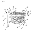
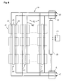
- Fig. 1 shows a first preferred embodiment of a fuel cell system in a perspective view.
- the fuel cell system comprises three layers 20, at which each layer 20 comprises three fuel cells 22.
- three fuel cells 22 are arranged in one column 43. Perpendicularly to the column 43, lines 45 are orientated.
- the column 43 of each layer 20 forms one supply unit 42 for each layer 20.
- the supply unit 42 consists of supply channels 42' for supplying anodes 23 and cathodes 25.
- the supply units 42 consist of means for cooling/warming up the fuel cells 22 and for conducting the existing water etc. These components are not shown in Fig. 1 .
- the columns 43 respectively the supply units and its supply channels 42' of each layer 20 are interconnected by a pressure equalization unit 44.
- reactant media Before reactant media is guided by a channel system 40 and from an inlet 60 to each layer 20, it passes valves 48. Valves 48 and the supply units 42 are interconnected by the distribution unit 46. Reactant media can be conducted in a direction of an outlet 62. Reactant media can also flow from the upmost layer 20 to the middle layer 20 and from there via the layer 20 at the very bottom to the outlet 62. Of course it is also possible that reactant media flows, coming from the inlet 60, directly to the layer 20 in the middle and/or to the layer 20 at the very bottom. The different flow designs are of course also mixable.
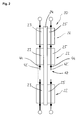
- Fig. 2 shows a preferred embodiment of a layer 20 in a side view. In other words the view is directed parallel to the layer 20.
- an electrolyte membrane 24 In the middle of Fig. 2 , one can see an electrolyte membrane 24.
- the electrolyte membrane 24 constitutes with at least three anodes 23 and at least three cathodes 25 at least three fuel cells 22.
- a column 43 of fuel cells 22 with at least three lines 45 of fuel cells 22.
- supply units 42 consisting of supply channels 42' are arranged.
- the layer 20 also comprises a cooling system and further supply channels 42'.
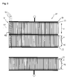
- Fig. 3 shows a plain view of a preferred embodiment of a layer 20.
- Three anodes 23 are shown, each with a length x along the orientation of supply units 42 that consist of supply channels 42'.
- the length x of cathodes 25, not visible in Fig. 3 is the same as the length x of the anodes 23.
- a plurality of supply units 42 is arranged in columns 43 in the preferred embodiment.
- the supply units 42 respectively the supply channels 42' are interconnected by pressure equalization units 44. After each pressure equalization unit 44, a new line 45 of fuel cells 22 begins. As it is shown in Fig. 3 , the pressure equalization units 44 can be arranged before and after fuel cells 22.
- Fig. 4 shows an electrical scheme of a layer 20 of a preferred embodiment of a fuel cell system.
- Three fuel cells 22 are shown that are connected in series (stack) along an electrolyte membrane 24. This means always an anode 23 of one fuel cell 22 is connected with a cathode 25 of a next fuel cell 22.
- Fig. 5a shows an electrical scheme of multiple layers 20 of a preferred embodiment of a fuel cell system.
- Fig. 5a shows three layers 20.
- Cells in each of the three layers 20 are connected in a stack and each of the three stacks is interconnected to the power management unit 80.
- Each of the layers 20 is interconnected with the power management unit 80.
- Each of the layers 20 comprises at least three fuel cells 22 which comprise an anode 23 and a cathode 25 that are arranged at an electrolyte membrane 24.
- Fig. 5b shows an electrical scheme of a preferred embodiment of multiple layers with a separate electrolyte membrane for every fuel cell. Apart from this, the structure is the same as in Fig. 5a .
- Fig. 5c shows another preferred electrical scheme of multiple layers 20 where all cells are interconnected directly to the power management unit 80.
- Fig. 6 shows a preferred embodiment of a channel system 40 of a preferred embodiment of a fuel cell system.
- the electrical connections are not shown in Fig. 6 .
- Each layer is supplied by supply units 42 consisting of supply channels 42'.
- the supply units 42 are part of the channel system 40.
- the channel system 40 comprises two inlets 60 and two outlets 62.
- the supply units 42 respectively the supply channels 42' supply the fuel cells 22 and especially the electrodes with fuel and oxidizing agent.
- the whole channel system 40 is interconnected by interfaces 82 with the power management unit 80.
- the layers 20 are supplied in a parallel way.
- the supply units 42 go straight from the inlets 60 over the layers 20 to the outlets 60. As one can see, a parallel arrangement of the supply units 42 represents a very short interconnection between the inlets 60 and the outlets 62.
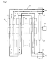
- Fig. 7 shows a preferred embodiment of a fuel cell system and a serial supply of different layers 20.
- Each layer 20 comprises fuel cells 22.
- Each fuel cell 22 comprises an anode 23 and a cathode 25.
- the fuel cells 22 are arranged along an electrolyte membrane 24. If reactant media comes from inlets 60 via the channel system 40 and supply units 42 respectively supply channels 42' to one layer 20, it does not go directly to the outlets 62, but to the next layer 20. So in opposite with the parallel flow, the way the reactant media has to pass between the inlets 60 and the outlets 62 is much longer. Consequently, the fuel usage is much better.
- the channel system 40 is controlled by a power management unit 80 comprising a control unit 82. It is further connected by interfaces 82 that make a controlling possible.
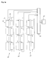
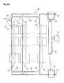
- Fig. 8a shows a preferred embodiment of a fuel cell system with a distribution unit 46.
- the distribution unit 46 contains a valve 48 for each layer 20. This configuration allows switching between parallel and serial supply methods.
- a power management 80 is adapted which comprises a control unit 81 and interfaces 82 which are adapted to control the valves 48.
- Fig. 8b shows a preferred embodiment of a switchable reactant supply with a separate electrolyte membrane for every fuel cell. Apart from this, the structure is the same as in Fig. 8a .
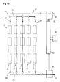
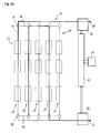
- Fig. 9a shows a preferred embodiment of a fuel cell system with a distribution unit 46 which comprises a valve 48 for each layer 20. Only the supply units 42 respectively the supply channels 42' for the fuel are depicted. Parts of a channel system 40 that are not used are shown in dotted lines. Thus, a serial supply method is possible by using the distribution units 46 and the valves 48. To control the supply method, a power management unit 80 with a control unit 81 and interfaces 82 are adapted. The supply method as it is shown in Fig. 9a is adapted for maximum fuel efficiency.
- Fig. 9b shows the same preferred embodiment as it is shown in Fig. 9a .
- the valves 48 work in a different way. So it is a kind of a combined serial and parallel supply method.
- Fig. 9c shows the same preferred embodiment as it is shown in Fig. 9a and 9b .
- the valves 48 are controlled in such a way that two supply units 42 are not used, so the third and the fifth layer 20 (counted from the left in Fig. 9c ) are not used.
Landscapes
- Life Sciences & Earth Sciences (AREA)
- Engineering & Computer Science (AREA)
- Manufacturing & Machinery (AREA)
- Sustainable Development (AREA)
- Sustainable Energy (AREA)
- Chemical & Material Sciences (AREA)
- Chemical Kinetics & Catalysis (AREA)
- Electrochemistry (AREA)
- General Chemical & Material Sciences (AREA)
- Fuel Cell (AREA)
Priority Applications (1)
| Application Number | Priority Date | Filing Date | Title |
|---|---|---|---|
| EP12191089.7A EP2728657A1 (fr) | 2012-11-02 | 2012-11-02 | Système de pile à combustible |
Applications Claiming Priority (1)
| Application Number | Priority Date | Filing Date | Title |
|---|---|---|---|
| EP12191089.7A EP2728657A1 (fr) | 2012-11-02 | 2012-11-02 | Système de pile à combustible |
Publications (1)
| Publication Number | Publication Date |
|---|---|
| EP2728657A1 true EP2728657A1 (fr) | 2014-05-07 |
Family
ID=47143667
Family Applications (1)
| Application Number | Title | Priority Date | Filing Date |
|---|---|---|---|
| EP12191089.7A Withdrawn EP2728657A1 (fr) | 2012-11-02 | 2012-11-02 | Système de pile à combustible |
Country Status (1)
| Country | Link |
|---|---|
| EP (1) | EP2728657A1 (fr) |
Cited By (1)
| Publication number | Priority date | Publication date | Assignee | Title |
|---|---|---|---|---|
| WO2016079481A1 (fr) * | 2014-11-17 | 2016-05-26 | Lg Fuel Cell Systems Inc. | Ensemble d'empilement de piles à combustible |
Citations (7)
| Publication number | Priority date | Publication date | Assignee | Title |
|---|---|---|---|---|
| US6558832B1 (en) * | 1998-04-30 | 2003-05-06 | Emitec Gesellschaft Fur Emissionstechnologie Mbh | Fuel cell module |
| US20030170520A1 (en) * | 2001-03-29 | 2003-09-11 | Satoru Fujii | High-polymer eletrolyte type thin film fuel cell and its driving method |
| US20040185319A1 (en) * | 2003-01-29 | 2004-09-23 | Honda Motor Co, Ltd. | Fuel cell system |
| DE102004003670A1 (de) * | 2003-12-12 | 2005-07-21 | Mtu Friedrichshafen Gmbh | Brennstoffzellenanordnung mit mehreren mittels eines Verteilermoduls zusammengeschalteten Brennstoffzellenmodulen und Verteilermodul |
| US20080152980A1 (en) * | 2006-12-21 | 2008-06-26 | Canon Kabushiki Kaisha | Membrane electrode assembly, method of producing the membrane electrode assembly, and fuel cell using the membrane electrode assembly |
| WO2010043767A1 (fr) * | 2008-10-17 | 2010-04-22 | Wärtsilä Finland Oy | Agencement de piles à combustible comprenant des empilements de piles à combustible |
| US20110269042A1 (en) * | 2010-07-21 | 2011-11-03 | Delphi Technologies, Inc. | Multiple stack fuel cell system with shared plenum |
-
2012
- 2012-11-02 EP EP12191089.7A patent/EP2728657A1/fr not_active Withdrawn
Patent Citations (7)
| Publication number | Priority date | Publication date | Assignee | Title |
|---|---|---|---|---|
| US6558832B1 (en) * | 1998-04-30 | 2003-05-06 | Emitec Gesellschaft Fur Emissionstechnologie Mbh | Fuel cell module |
| US20030170520A1 (en) * | 2001-03-29 | 2003-09-11 | Satoru Fujii | High-polymer eletrolyte type thin film fuel cell and its driving method |
| US20040185319A1 (en) * | 2003-01-29 | 2004-09-23 | Honda Motor Co, Ltd. | Fuel cell system |
| DE102004003670A1 (de) * | 2003-12-12 | 2005-07-21 | Mtu Friedrichshafen Gmbh | Brennstoffzellenanordnung mit mehreren mittels eines Verteilermoduls zusammengeschalteten Brennstoffzellenmodulen und Verteilermodul |
| US20080152980A1 (en) * | 2006-12-21 | 2008-06-26 | Canon Kabushiki Kaisha | Membrane electrode assembly, method of producing the membrane electrode assembly, and fuel cell using the membrane electrode assembly |
| WO2010043767A1 (fr) * | 2008-10-17 | 2010-04-22 | Wärtsilä Finland Oy | Agencement de piles à combustible comprenant des empilements de piles à combustible |
| US20110269042A1 (en) * | 2010-07-21 | 2011-11-03 | Delphi Technologies, Inc. | Multiple stack fuel cell system with shared plenum |
Cited By (2)
| Publication number | Priority date | Publication date | Assignee | Title |
|---|---|---|---|---|
| WO2016079481A1 (fr) * | 2014-11-17 | 2016-05-26 | Lg Fuel Cell Systems Inc. | Ensemble d'empilement de piles à combustible |
| US9640828B2 (en) | 2014-11-17 | 2017-05-02 | Lg Fuel Cell Systems Inc. | Fuel cell stack assembly |
Similar Documents
| Publication | Publication Date | Title |
|---|---|---|
| EP2179466B1 (fr) | Batterie électrochimique comprenant des collecteurs internes | |
| EP2795697B1 (fr) | Batterie à circulation ayant une circulation mélangée | |
| CA2516749C (fr) | Conception de champs d'ecoulement | |
| JP7449228B2 (ja) | 改善された流体流れ設計を伴うpem燃料セル | |
| KR102861217B1 (ko) | 고전압 연료 전지 스택 | |
| JP7024096B2 (ja) | バイポーラプレート、燃料電池および自動車 | |
| US11271241B1 (en) | Stackable fuel cell | |
| US20240396060A1 (en) | A fuel cell | |
| US20200266457A1 (en) | Multipoint electrolyte flow field embodiment for vanadium redox flow battery | |
| CN110073532A (zh) | 用于燃料电池的双极板和燃料电池 | |
| KR20170012311A (ko) | 전기 화학 셀에 사용하기 위한 유동장들 | |
| KR102027117B1 (ko) | 연료 전지용 집전판 및 이를 포함하는 스택 구조물 | |
| CN101931089A (zh) | 燃料电池系统及其电堆 | |
| US10158141B2 (en) | Fuel cell system including multiple fuel cell stacks | |
| EP2728657A1 (fr) | Système de pile à combustible | |
| CN115552669A (zh) | 双极板 | |
| EP3008769B1 (fr) | Batterie à flux à passage de collecteurs qui varie en section transversale | |
| JP7085930B2 (ja) | 燃料電池スタック組立体 | |
| KR101184930B1 (ko) | 연료 전지 시스템의 다단 스택 조립체 | |
| JP2023528225A (ja) | レドックスフロー電池システム及びオールアイアンフロー電池 | |
| KR101486168B1 (ko) | 연료전지 바이폴라-플레이트 및 이를 포함하는 연료전지 스택 | |
| CN116031431B (zh) | 双极流板结构、燃料电池、燃料电池堆系统 | |
| KR100569421B1 (ko) | 자동차의 연료전지용 분리판 구조 | |
| WO2024201083A1 (fr) | Pile à combustible | |
| WO2018091070A1 (fr) | Système électrochimique bipolaire |
Legal Events
| Date | Code | Title | Description |
|---|---|---|---|
| PUAI | Public reference made under article 153(3) epc to a published international application that has entered the european phase |
Free format text: ORIGINAL CODE: 0009012 |
|
| 17P | Request for examination filed |
Effective date: 20121102 |
|
| AK | Designated contracting states |
Kind code of ref document: A1 Designated state(s): AL AT BE BG CH CY CZ DE DK EE ES FI FR GB GR HR HU IE IS IT LI LT LU LV MC MK MT NL NO PL PT RO RS SE SI SK SM TR |
|
| AX | Request for extension of the european patent |
Extension state: BA ME |
|
| STAA | Information on the status of an ep patent application or granted ep patent |
Free format text: STATUS: THE APPLICATION IS DEEMED TO BE WITHDRAWN |
|
| 18D | Application deemed to be withdrawn |
Effective date: 20141108 |