EP2728720A2 - Bürstenloser Gleichstrommotor mit Außenläufer - Google Patents
Bürstenloser Gleichstrommotor mit Außenläufer Download PDFInfo
- Publication number
- EP2728720A2 EP2728720A2 EP13180365.2A EP13180365A EP2728720A2 EP 2728720 A2 EP2728720 A2 EP 2728720A2 EP 13180365 A EP13180365 A EP 13180365A EP 2728720 A2 EP2728720 A2 EP 2728720A2
- Authority
- EP
- European Patent Office
- Prior art keywords
- housing
- end cover
- shaft
- motor
- stator assembly
- Prior art date
- Legal status (The legal status is an assumption and is not a legal conclusion. Google has not performed a legal analysis and makes no representation as to the accuracy of the status listed.)
- Granted
Links
Images



Classifications
-
- H—ELECTRICITY
- H02—GENERATION; CONVERSION OR DISTRIBUTION OF ELECTRIC POWER
- H02K—DYNAMO-ELECTRIC MACHINES
- H02K5/00—Casings; Enclosures; Supports
- H02K5/04—Casings or enclosures characterised by the shape, form or construction thereof
- H02K5/16—Means for supporting bearings, e.g. insulating supports or means for fitting bearings in the bearing-shields
- H02K5/165—Means for supporting bearings, e.g. insulating supports or means for fitting bearings in the bearing-shields radially supporting the rotor around a fixed spindle; radially supporting the rotor directly
-
- H—ELECTRICITY
- H02—GENERATION; CONVERSION OR DISTRIBUTION OF ELECTRIC POWER
- H02K—DYNAMO-ELECTRIC MACHINES
- H02K21/00—Synchronous motors having permanent magnets; Synchronous generators having permanent magnets
- H02K21/12—Synchronous motors having permanent magnets; Synchronous generators having permanent magnets with stationary armatures and rotating magnets
- H02K21/22—Synchronous motors having permanent magnets; Synchronous generators having permanent magnets with stationary armatures and rotating magnets with magnets rotating around the armatures, e.g. flywheel magnetos
-
- H—ELECTRICITY
- H02—GENERATION; CONVERSION OR DISTRIBUTION OF ELECTRIC POWER
- H02K—DYNAMO-ELECTRIC MACHINES
- H02K1/00—Details of the magnetic circuit
- H02K1/06—Details of the magnetic circuit characterised by the shape, form or construction
- H02K1/22—Rotating parts of the magnetic circuit
- H02K1/27—Rotor cores with permanent magnets
- H02K1/2786—Outer rotors
- H02K1/2787—Outer rotors the magnetisation axis of the magnets being perpendicular to the rotor axis
- H02K1/2789—Outer rotors the magnetisation axis of the magnets being perpendicular to the rotor axis the rotor consisting of two or more circumferentially positioned magnets
- H02K1/2791—Surface mounted magnets; Inset magnets
-
- H—ELECTRICITY
- H02—GENERATION; CONVERSION OR DISTRIBUTION OF ELECTRIC POWER
- H02K—DYNAMO-ELECTRIC MACHINES
- H02K1/00—Details of the magnetic circuit
- H02K1/06—Details of the magnetic circuit characterised by the shape, form or construction
- H02K1/22—Rotating parts of the magnetic circuit
- H02K1/28—Means for mounting or fastening rotating magnetic parts on to, or to, the rotor structures
-
- H—ELECTRICITY
- H02—GENERATION; CONVERSION OR DISTRIBUTION OF ELECTRIC POWER
- H02K—DYNAMO-ELECTRIC MACHINES
- H02K11/00—Structural association of dynamo-electric machines with electric components or with devices for shielding, monitoring or protection
- H02K11/0094—Structural association with other electrical or electronic devices
-
- H—ELECTRICITY
- H02—GENERATION; CONVERSION OR DISTRIBUTION OF ELECTRIC POWER
- H02K—DYNAMO-ELECTRIC MACHINES
- H02K7/00—Arrangements for handling mechanical energy structurally associated with dynamo-electric machines, e.g. structural association with mechanical driving motors or auxiliary dynamo-electric machines
- H02K7/003—Couplings; Details of shafts
Definitions
- the invention relates to a DC brushless motor having an external rotor.
- a typical DC brushless motor having an external rotor
- one end of a shaft is connected with a rotor body; the other end of the shaft is connected with a flange, so that the shaft rotates along with the rotor and drives the flange to rotate.
- the rotor is disposed on one side; a force is unevenly distributed on the motor.
- a DC brushless motor having an external rotor, comprising: a shaft; a stator assembly; an end cover, the end cover comprising a bearing; a housing, the housing comprising: an end, and an inner wall; and a plurality of permanent magnets.
- the shaft is connected with the stator assembly; the stator assembly is arranged inside the housing.
- the permanent magnets are positioned outside the stator assembly on the inner wall of the housing.
- the end cover is disposed on the end of the housing.
- the shaft is disposed on the bearing of the end cover.
- a plurality of mounting bosses is disposed on the end of the housing above end surfaces of the permanent magnets.
- Each mounting boss comprises a threaded hole.
- the end cover comprises a through hole.
- a screw passes through the through hole of the end cover and is screwed into the threaded hole for fixing the end cover on the housing.
- a gap is arranged in an axial direction on a side wall of the end cover outside the through hole.
- a recess in a ring shape is arranged on the side wall of the end cover. The gap is in communication with the recess.
- An end of the inner wall of the housing is convex to form a fixture block. The fixture block passes through the gap and is inserted into the recess.
- An end surface of the end cover is provided with a plurality of clay recesses for correcting a dynamic balance.
- a mounting bracket is arranged outside the housing.
- the stator assembly comprises: a stator core, and a winding.
- the winding is wound on the stator core.
- One end of an external lead is connected with one end of the winding; and the other end of the external lead passes through a shaft hole of the shaft.
- the permanent magnets are stuck to the inner wall of the housing by glue.
- the DC brushless motor having an external rotor of the invention comprises: the shaft, the stator assembly, the end cover, the housing, and a plurality of permanent magnets.
- the shaft is connected with the stator assembly.
- the stator assembly is arranged inside the housing.
- the permanent magnets are positioned outside the stator assembly on the inner wall of the housing.
- the end cover is disposed on the end of the housing.
- the shaft is disposed on a bearing of the end cover.
- a plurality of mounting bosses is disposed on the end of the housing above end surfaces of the permanent magnets.
- the threaded hole is disposed on the mounting boss.
- the screw passes through a through hole of the end cover and is screwed into the threaded hole for fixing the end cover on the housing.
- the structure is reasonably designed, and the connection is firm.
- the gap is arranged in the axial direction on a side wall of the end cover outside the through hole.
- the recess in a ring shape is arranged on the side wall of the end cover.
- the gap is in communication with the recess.
- the end of the inner wall of the housing is convex to form the fixture block, and the fixture block passes through the gap and is inserted into the recess.
- the end cover is fixed in the axial direction.
- An end surface of the end cover is provided with a plurality of clay recesses for correcting a dynamic balance.
- Clay used to correct the dynamic balance is disposed on the clay recesses.
- the mounting bracket is arranged outside the housing; the mounting bracket is connected having an external wind wheel, which has an even force distribution and firm connection.
- FIG. 1 is a stereogram of a DC brushless motor having an external rotor in accordance with one embodiment of the invention
- FIG. 2 is an exploded view of a DC brushless motor having an external rotor in accordance with one embodiment of the invention
- FIG. 3 is a structure diagram of a DC brushless motor having an external rotor in accordance with one embodiment of the invention
- FIG. 4 is a cross sectional view of FIG. 3 taken from line A-A;
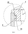
- FIG. 5 is an enlarged view of part B-B of FIG. 4 ;
- FIG. 6 is an enlarged view of part C-C of FIG. 4 ;
- FIG. 7 is a stereogram of an end cover in accordance with one embodiment of the invention.
- a DC brushless motor having an external rotor comprises: a shaft 1, a stator assembly 2, an end cover 3, a housing 4, and a plurality of permanent magnets 5.
- the shaft 1 is connected with the stator assembly 2.
- the stator assembly 2 is arranged inside the housing 4.
- the permanent magnets 5 are positioned outside the stator assembly 2 on an inner wall of the housing 4.
- the end cover 3 is disposed on an end of the housing 4.
- the shaft 1 is disposed on a bearing 6 of the end cover 3.
- a plurality of mounting bosses 41 is disposed on the end of the housing 4 above end surfaces of the permanent magnets 5.
- a threaded hole 410 is disposed on each mounting boss 41.
- a screw 7 passes through a through hole 31 of the end cover 3 and is screwed into the threaded hole 410 for fixing the end cover 3 on the housing 4.
- a gap 32 is arranged in an axial direction on a side wall of the end cover 3 outside the through hole 31.
- a recess 33 in a ring shape is arranged on the side wall of the end cover 3.
- the gap 32 is in communication with the recess 33.
- An end of the inner wall of the housing 4 is convex to form a fixture block 42, and the fixture block 42 passes through the gap 32 and is inserted into the recess 33.
- an end surface of the end cover 3 is provided with a plurality of clay recesses 34 for correcting a dynamic balance.
- a mounting bracket 8 is arranged outside the housing 4.
- the stator assembly 2 comprises: a stator core 21, and a winding 22.
- the winding 22 is wound on the stator core 21.
- One end of an external lead 9 is connected with one end of the winding 22; the other end of the external lead 9 passes through a shaft hole 11 of the shaft 1.
- the motor comprises: the shaft 1, the stator assembly 2, the end cover 3, the housing 4, and a plurality of permanent magnets 5.
- the shaft 1 is connected with the stator assembly 2.
- the stator assembly 2 is arranged inside the housing 4.
- a plurality of permanent magnets 5 is positioned outside the stator assembly 2 on the inner wall of the housing 4.
- the axial gap 23 and the annular recess 33 are arranged on the side wall of the end cover.
- the gap 32 is in communication with the recess 33.
- the fixture block 42 is arranged on the end of the inner wall of the housing 4.
- the fixture block 42 passes through the gap 32 of the end cover 3 and is inserted into the recess 33 to allow the through hole 31 of the end cover 3 to align with the threaded hole 410 of the mounting boss 41 of the housing 4, so that the end cover 3 is fixed on the housing 4 by inserting the screw 7 into the through hole 31 and the threaded hole 410.
Landscapes
- Engineering & Computer Science (AREA)
- Power Engineering (AREA)
- Motor Or Generator Frames (AREA)
- Permanent Magnet Type Synchronous Machine (AREA)
- Connection Of Motors, Electrical Generators, Mechanical Devices, And The Like (AREA)
Applications Claiming Priority (1)
| Application Number | Priority Date | Filing Date | Title |
|---|---|---|---|
| CN2012205695412U CN202918162U (zh) | 2012-10-31 | 2012-10-31 | 一种直流无刷外转子电机结构 |
Publications (4)
| Publication Number | Publication Date |
|---|---|
| EP2728720A2 true EP2728720A2 (de) | 2014-05-07 |
| EP2728720A3 EP2728720A3 (de) | 2017-08-30 |
| EP2728720C0 EP2728720C0 (de) | 2024-07-17 |
| EP2728720B1 EP2728720B1 (de) | 2024-07-17 |
Family
ID=48166438
Family Applications (1)
| Application Number | Title | Priority Date | Filing Date |
|---|---|---|---|
| EP13180365.2A Active EP2728720B1 (de) | 2012-10-31 | 2013-08-14 | Bürstenloser Gleichstrommotor mit Außenläufer |
Country Status (5)
| Country | Link |
|---|---|
| US (1) | US9385572B2 (de) |
| EP (1) | EP2728720B1 (de) |
| CN (1) | CN202918162U (de) |
| CA (1) | CA2828314C (de) |
| MX (1) | MX2013011036A (de) |
Cited By (2)
| Publication number | Priority date | Publication date | Assignee | Title |
|---|---|---|---|---|
| EP3349332A4 (de) * | 2015-09-08 | 2019-05-01 | LG Electronics Inc. | Rotor und motor damit |
| US10326325B2 (en) | 2015-09-08 | 2019-06-18 | Lg Electronics Inc. | Rotor and motor including the same |
Families Citing this family (24)
| Publication number | Priority date | Publication date | Assignee | Title |
|---|---|---|---|---|
| DE102013110999A1 (de) * | 2013-10-02 | 2015-04-02 | Ebm-Papst St. Georgen Gmbh & Co. Kg | Elektromotor |
| CN203775003U (zh) * | 2014-03-24 | 2014-08-13 | 中山大洋电机制造有限公司 | 一种直流无刷外转子电机及其应用的鼓风机 |
| CN105099041A (zh) * | 2014-04-22 | 2015-11-25 | 德昌电机(深圳)有限公司 | 无刷电机、无刷电机的外转子及其制造方法 |
| WO2016155271A1 (zh) | 2015-03-31 | 2016-10-06 | 中山大洋电机股份有限公司 | 一种直流无刷电机 |
| CN204858809U (zh) * | 2015-08-15 | 2015-12-09 | 中山大洋电机股份有限公司 | 一种直流无刷电机 |
| CN204497938U (zh) * | 2015-03-31 | 2015-07-22 | 中山大洋电机股份有限公司 | 一种外转子电机 |
| TWI572120B (zh) * | 2015-11-24 | 2017-02-21 | 建準電機工業股份有限公司 | Motor rotor |
| CN105449888A (zh) * | 2015-12-25 | 2016-03-30 | 广州亿航智能技术有限公司 | 无刷直流电动机 |
| CN105529844A (zh) * | 2016-01-12 | 2016-04-27 | 张大鹏 | 永磁式低静态力矩低速三相交流发电机 |
| DE102016214131A1 (de) * | 2016-08-01 | 2018-02-01 | Robert Bosch Gmbh | Elektrische Maschineneinheit mit Nut zur Aufnahme einer Schutzkappe |
| CN106640702A (zh) * | 2016-11-29 | 2017-05-10 | 佛山市顺德区卓高电机制造有限公司 | 一种直流无刷风机装置 |
| CN106685111B (zh) * | 2017-03-31 | 2023-09-12 | 深圳市正德智控股份有限公司 | 一种直流电机 |
| CN108880160B (zh) * | 2018-07-26 | 2019-10-25 | 深圳市易美迅智能科技有限公司 | 具有无线充电的电动辊筒 |
| CN108933503B (zh) * | 2018-07-26 | 2019-09-10 | 深圳市易美迅智能科技有限公司 | 具有wifi功能的电动辊筒 |
| CN108832767B (zh) * | 2018-07-26 | 2019-12-31 | 深圳市易美迅智能科技有限公司 | 电动辊筒 |
| US11190080B2 (en) * | 2019-09-30 | 2021-11-30 | Kuo-Tsun Lin | Ceiling fan motor housing with L-shaped positioning member with horizontal portion to support bottom end of cover |
| US11359672B2 (en) * | 2019-12-10 | 2022-06-14 | Koch Engineered Solutions, Llc | Bearing assembly for rotary electric machine |
| EP4127474B1 (de) | 2020-03-31 | 2025-03-12 | Graco Minnesota Inc. | Pumpenantriebssystem |
| CN115335601A (zh) | 2020-03-31 | 2022-11-11 | 固瑞克明尼苏达有限公司 | 用于多组分喷涂系统的电操作泵 |
| EP4596881A3 (de) | 2020-03-31 | 2025-08-13 | Graco Minnesota Inc. | Elektrisch angetriebene linearpumpe |
| CN116780806A (zh) * | 2022-03-11 | 2023-09-19 | 操纵技术Ip控股公司 | 马达防尘盖设计和与联轴器的接口 |
| US12689249B2 (en) | 2022-12-02 | 2026-07-21 | Milwaukee Electric Tool Corporation | Electric motor |
| CN117650643B (zh) * | 2024-01-30 | 2024-04-05 | 上海舟水电器有限公司 | 一种吸尘器用节能环保无刷直流电机 |
| US12651939B2 (en) * | 2024-05-22 | 2026-06-09 | Air Cool Industrial Co., Ltd. | Motor housing structure for ceiling fan |
Family Cites Families (24)
| Publication number | Priority date | Publication date | Assignee | Title |
|---|---|---|---|---|
| US1411442A (en) * | 1921-03-14 | 1922-04-04 | Leece Neville Co | Dynamo-electric machine |
| US2722618A (en) * | 1952-07-08 | 1955-11-01 | Gen Electric | Dynamoelectric machine |
| US3303365A (en) * | 1964-05-04 | 1967-02-07 | Robbins & Myers | Motor housing with an output shaft mounted in a rotatable bell housing |
| US3359439A (en) * | 1965-08-23 | 1967-12-19 | Akai Electric | Electric motor |
| BE758737A (fr) * | 1969-11-11 | 1971-04-16 | Gutris Giorgio | Methode pour le montage de moteurs electriques, et moteurs montes seloncette methode |
| USRE37058E1 (en) * | 1980-05-10 | 2001-02-20 | Papst Licensing Gmbh & Co. Kg | Disk storage device having contamination seals |
| JPS6055278U (ja) * | 1983-09-22 | 1985-04-18 | 三菱電機株式会社 | 回転電機のアマチユア |
| JPH01157565U (de) * | 1988-04-12 | 1989-10-31 | ||
| JPH0486063U (de) * | 1990-11-28 | 1992-07-27 | ||
| DE4039571C2 (de) * | 1990-12-12 | 1999-01-07 | Mulfingen Elektrobau Ebm | Kollektorloser Außenläufermotor mit lösbar befestigten Lagerschilden |
| US5679989A (en) * | 1995-02-15 | 1997-10-21 | J. H. Buscher, Inc. | Torque motors with enhanced reliability |
| US5861694A (en) * | 1996-06-28 | 1999-01-19 | Ryobi North America Inc. | Field retaining mechanism for a permanent magnet D.C. motor |
| US5932942A (en) * | 1997-12-16 | 1999-08-03 | Reliance Electric Industrial Company | DC motor drive with improved thermal characteristics |
| ES2301228T3 (es) * | 1999-01-08 | 2008-06-16 | Lg Electronics Inc. | Estructura de rotor para un motor sin escobillas de tipo con rotor externo. |
| US6664436B2 (en) * | 2001-07-24 | 2003-12-16 | Kimberly-Clark Worldwide, Inc. | Disposable products having humidity activated materials with shape-memory |
| DE20212074U1 (de) * | 2002-08-06 | 2002-11-07 | Lee, Ying-Che, Taipeh/T'ai-pei | Außenläufermotor für ein Laufband |
| AU2003250569A1 (en) * | 2003-07-25 | 2005-02-14 | Lg Electronics Inc. | Pistion assembly of cooler |
| US20060238059A1 (en) * | 2003-08-19 | 2006-10-26 | Fumito Komatsu | Synchronous motor |
| US6943478B2 (en) * | 2003-11-14 | 2005-09-13 | Dura-Trac Motors, Inc. | Brushless permanent magnet wheel motor with variable axial rotor/stator alignment |
| CN201226473Y (zh) * | 2008-06-16 | 2009-04-22 | 中山大洋电机股份有限公司 | 一种电机端盖的装配结构 |
| KR101098748B1 (ko) * | 2009-10-01 | 2011-12-23 | (주) 디에이치홀딩스 | 브러쉬리스 직류모터 |
| AU2011100860A4 (en) * | 2011-07-13 | 2011-10-06 | Hengdian Group Linix Motor Co., Ltd. | Direct current permanent magnet motor |
| EP2741982B1 (de) * | 2011-08-11 | 2016-10-12 | Mol Belting Systems, Inc. | Montageflächensystem |
| CN202218127U (zh) * | 2011-09-07 | 2012-05-09 | 东莞市特仕电机科技有限公司 | 一种电机转子平衡板 |
-
2012
- 2012-10-31 CN CN2012205695412U patent/CN202918162U/zh not_active Expired - Fee Related
-
2013
- 2013-03-16 US US13/844,968 patent/US9385572B2/en active Active
- 2013-08-14 EP EP13180365.2A patent/EP2728720B1/de active Active
- 2013-09-24 CA CA2828314A patent/CA2828314C/en active Active
- 2013-09-25 MX MX2013011036A patent/MX2013011036A/es active IP Right Grant
Non-Patent Citations (1)
| Title |
|---|
| None |
Cited By (2)
| Publication number | Priority date | Publication date | Assignee | Title |
|---|---|---|---|---|
| EP3349332A4 (de) * | 2015-09-08 | 2019-05-01 | LG Electronics Inc. | Rotor und motor damit |
| US10326325B2 (en) | 2015-09-08 | 2019-06-18 | Lg Electronics Inc. | Rotor and motor including the same |
Also Published As
| Publication number | Publication date |
|---|---|
| CN202918162U (zh) | 2013-05-01 |
| CA2828314C (en) | 2017-08-15 |
| CA2828314A1 (en) | 2014-04-30 |
| EP2728720C0 (de) | 2024-07-17 |
| US20140117799A1 (en) | 2014-05-01 |
| EP2728720B1 (de) | 2024-07-17 |
| US9385572B2 (en) | 2016-07-05 |
| MX2013011036A (es) | 2014-04-29 |
| EP2728720A3 (de) | 2017-08-30 |
Similar Documents
| Publication | Publication Date | Title |
|---|---|---|
| US9385572B2 (en) | DC brushless motor with external rotor | |
| KR102384550B1 (ko) | 전기 모터 | |
| US9033680B2 (en) | Electric fan | |
| CN105370584B (zh) | 电动泵 | |
| EP3035508A3 (de) | Bürstenlose motoranordnung für ein befestigungswerkzeug | |
| EP2597761A3 (de) | Elektrischer Motor und elektrische Einheit damit | |
| US20160020656A1 (en) | Electric machine, rotor and associated method | |
| US20150056088A1 (en) | Inner-rotor fan | |
| CN202737600U (zh) | 电机转子及电机 | |
| WO2015143853A1 (zh) | 一种直流无刷外转子电机及其应用的鼓风机 | |
| WO2011096658A3 (en) | Traction motor module | |
| JP2014197948A (ja) | 永久磁石電動機 | |
| CN203416091U (zh) | 防震胶圈及电机 | |
| WO2019208126A1 (ja) | モータ | |
| WO2019053669A3 (en) | Electrical motor arrangement for electrical vehicles | |
| KR101870450B1 (ko) | 모터 | |
| KR20170045997A (ko) | 로터 코어, 로터 조립체 및 이를 포함하는 모터 | |
| CN104506009A (zh) | 无刷电动机 | |
| CN201611834U (zh) | 电动车电机 | |
| WO2016026364A1 (zh) | 由电机驱动的转动部件、电机及风机 | |
| KR102361355B1 (ko) | 샤프트 로터 및 이를 구비하는 모터 | |
| CN104505966A (zh) | 外转子无刷电动机 | |
| CN202190187U (zh) | 一种电机的机壳与定子铁芯的安装结构 | |
| CN203261177U (zh) | 建筑机械用复合构造体 | |
| CN102290948A (zh) | 一种内转子无刷电机 |
Legal Events
| Date | Code | Title | Description |
|---|---|---|---|
| PUAI | Public reference made under article 153(3) epc to a published international application that has entered the european phase |
Free format text: ORIGINAL CODE: 0009012 |
|
| 17P | Request for examination filed |
Effective date: 20130814 |
|
| AK | Designated contracting states |
Kind code of ref document: A2 Designated state(s): AL AT BE BG CH CY CZ DE DK EE ES FI FR GB GR HR HU IE IS IT LI LT LU LV MC MK MT NL NO PL PT RO RS SE SI SK SM TR |
|
| AX | Request for extension of the european patent |
Extension state: BA ME |
|
| 17P | Request for examination filed |
Effective date: 20141030 |
|
| RBV | Designated contracting states (corrected) |
Designated state(s): AL AT BE BG CH CY CZ DE DK EE ES FI FR GB GR HR HU IE IS IT LI LT LU LV MC MK MT NL NO PL PT RO RS SE SI SK SM TR |
|
| PUAL | Search report despatched |
Free format text: ORIGINAL CODE: 0009013 |
|
| AK | Designated contracting states |
Kind code of ref document: A3 Designated state(s): AL AT BE BG CH CY CZ DE DK EE ES FI FR GB GR HR HU IE IS IT LI LT LU LV MC MK MT NL NO PL PT RO RS SE SI SK SM TR |
|
| AX | Request for extension of the european patent |
Extension state: BA ME |
|
| RIC1 | Information provided on ipc code assigned before grant |
Ipc: H02K 5/16 20060101ALI20170727BHEP Ipc: H02K 21/22 20060101AFI20170727BHEP Ipc: H02K 7/00 20060101ALI20170727BHEP |
|
| STAA | Information on the status of an ep patent application or granted ep patent |
Free format text: STATUS: EXAMINATION IS IN PROGRESS |
|
| 17Q | First examination report despatched |
Effective date: 20180514 |
|
| 19U | Interruption of proceedings before grant |
Effective date: 20190614 |
|
| 19W | Proceedings resumed before grant after interruption of proceedings |
Effective date: 20210322 |
|
| REG | Reference to a national code |
Ref country code: DE Free format text: PREVIOUS MAIN CLASS: H02K0021220000 Ipc: H02K0001279100 Ref country code: DE Ref legal event code: R079 Ref document number: 602013085905 Country of ref document: DE Free format text: PREVIOUS MAIN CLASS: H02K0021220000 Ipc: H02K0001279100 |
|
| GRAP | Despatch of communication of intention to grant a patent |
Free format text: ORIGINAL CODE: EPIDOSNIGR1 |
|
| STAA | Information on the status of an ep patent application or granted ep patent |
Free format text: STATUS: GRANT OF PATENT IS INTENDED |
|
| RIC1 | Information provided on ipc code assigned before grant |
Ipc: H02K 7/00 20060101ALI20240123BHEP Ipc: H02K 21/22 20060101ALI20240123BHEP Ipc: H02K 1/2791 20220101AFI20240123BHEP |
|
| INTG | Intention to grant announced |
Effective date: 20240209 |
|
| GRAS | Grant fee paid |
Free format text: ORIGINAL CODE: EPIDOSNIGR3 |
|
| GRAA | (expected) grant |
Free format text: ORIGINAL CODE: 0009210 |
|
| STAA | Information on the status of an ep patent application or granted ep patent |
Free format text: STATUS: THE PATENT HAS BEEN GRANTED |
|
| AK | Designated contracting states |
Kind code of ref document: B1 Designated state(s): AL AT BE BG CH CY CZ DE DK EE ES FI FR GB GR HR HU IE IS IT LI LT LU LV MC MK MT NL NO PL PT RO RS SE SI SK SM TR |
|
| REG | Reference to a national code |
Ref country code: GB Ref legal event code: FG4D |
|
| REG | Reference to a national code |
Ref country code: CH Ref legal event code: EP |
|
| REG | Reference to a national code |
Ref country code: DE Ref legal event code: R096 Ref document number: 602013085905 Country of ref document: DE |
|
| REG | Reference to a national code |
Ref country code: IE Ref legal event code: FG4D |
|
| U01 | Request for unitary effect filed |
Effective date: 20240731 |
|
| U07 | Unitary effect registered |
Designated state(s): AT BE BG DE DK EE FI FR IT LT LU LV MT NL PT SE SI Effective date: 20240820 |
|
| U20 | Renewal fee for the european patent with unitary effect paid |
Year of fee payment: 12 Effective date: 20240816 |
|
| PG25 | Lapsed in a contracting state [announced via postgrant information from national office to epo] |
Ref country code: NO Free format text: LAPSE BECAUSE OF FAILURE TO SUBMIT A TRANSLATION OF THE DESCRIPTION OR TO PAY THE FEE WITHIN THE PRESCRIBED TIME-LIMIT Effective date: 20241017 |
|
| PG25 | Lapsed in a contracting state [announced via postgrant information from national office to epo] |
Ref country code: GR Free format text: LAPSE BECAUSE OF FAILURE TO SUBMIT A TRANSLATION OF THE DESCRIPTION OR TO PAY THE FEE WITHIN THE PRESCRIBED TIME-LIMIT Effective date: 20241018 Ref country code: PL Free format text: LAPSE BECAUSE OF FAILURE TO SUBMIT A TRANSLATION OF THE DESCRIPTION OR TO PAY THE FEE WITHIN THE PRESCRIBED TIME-LIMIT Effective date: 20240717 |
|
| PG25 | Lapsed in a contracting state [announced via postgrant information from national office to epo] |
Ref country code: IS Free format text: LAPSE BECAUSE OF FAILURE TO SUBMIT A TRANSLATION OF THE DESCRIPTION OR TO PAY THE FEE WITHIN THE PRESCRIBED TIME-LIMIT Effective date: 20241117 |
|
| PG25 | Lapsed in a contracting state [announced via postgrant information from national office to epo] |
Ref country code: HR Free format text: LAPSE BECAUSE OF FAILURE TO SUBMIT A TRANSLATION OF THE DESCRIPTION OR TO PAY THE FEE WITHIN THE PRESCRIBED TIME-LIMIT Effective date: 20240717 |
|
| PG25 | Lapsed in a contracting state [announced via postgrant information from national office to epo] |
Ref country code: ES Free format text: LAPSE BECAUSE OF FAILURE TO SUBMIT A TRANSLATION OF THE DESCRIPTION OR TO PAY THE FEE WITHIN THE PRESCRIBED TIME-LIMIT Effective date: 20240717 Ref country code: RS Free format text: LAPSE BECAUSE OF FAILURE TO SUBMIT A TRANSLATION OF THE DESCRIPTION OR TO PAY THE FEE WITHIN THE PRESCRIBED TIME-LIMIT Effective date: 20241017 |
|
| PG25 | Lapsed in a contracting state [announced via postgrant information from national office to epo] |
Ref country code: RS Free format text: LAPSE BECAUSE OF FAILURE TO SUBMIT A TRANSLATION OF THE DESCRIPTION OR TO PAY THE FEE WITHIN THE PRESCRIBED TIME-LIMIT Effective date: 20241017 Ref country code: PL Free format text: LAPSE BECAUSE OF FAILURE TO SUBMIT A TRANSLATION OF THE DESCRIPTION OR TO PAY THE FEE WITHIN THE PRESCRIBED TIME-LIMIT Effective date: 20240717 Ref country code: NO Free format text: LAPSE BECAUSE OF FAILURE TO SUBMIT A TRANSLATION OF THE DESCRIPTION OR TO PAY THE FEE WITHIN THE PRESCRIBED TIME-LIMIT Effective date: 20241017 Ref country code: IS Free format text: LAPSE BECAUSE OF FAILURE TO SUBMIT A TRANSLATION OF THE DESCRIPTION OR TO PAY THE FEE WITHIN THE PRESCRIBED TIME-LIMIT Effective date: 20241117 Ref country code: HR Free format text: LAPSE BECAUSE OF FAILURE TO SUBMIT A TRANSLATION OF THE DESCRIPTION OR TO PAY THE FEE WITHIN THE PRESCRIBED TIME-LIMIT Effective date: 20240717 Ref country code: GR Free format text: LAPSE BECAUSE OF FAILURE TO SUBMIT A TRANSLATION OF THE DESCRIPTION OR TO PAY THE FEE WITHIN THE PRESCRIBED TIME-LIMIT Effective date: 20241018 Ref country code: ES Free format text: LAPSE BECAUSE OF FAILURE TO SUBMIT A TRANSLATION OF THE DESCRIPTION OR TO PAY THE FEE WITHIN THE PRESCRIBED TIME-LIMIT Effective date: 20240717 |
|
| REG | Reference to a national code |
Ref country code: CH Ref legal event code: PL |
|
| PG25 | Lapsed in a contracting state [announced via postgrant information from national office to epo] |
Ref country code: SM Free format text: LAPSE BECAUSE OF FAILURE TO SUBMIT A TRANSLATION OF THE DESCRIPTION OR TO PAY THE FEE WITHIN THE PRESCRIBED TIME-LIMIT Effective date: 20240717 |
|
| PG25 | Lapsed in a contracting state [announced via postgrant information from national office to epo] |
Ref country code: MC Free format text: LAPSE BECAUSE OF FAILURE TO SUBMIT A TRANSLATION OF THE DESCRIPTION OR TO PAY THE FEE WITHIN THE PRESCRIBED TIME-LIMIT Effective date: 20240717 Ref country code: CH Free format text: LAPSE BECAUSE OF NON-PAYMENT OF DUE FEES Effective date: 20240831 |
|
| PG25 | Lapsed in a contracting state [announced via postgrant information from national office to epo] |
Ref country code: CZ Free format text: LAPSE BECAUSE OF FAILURE TO SUBMIT A TRANSLATION OF THE DESCRIPTION OR TO PAY THE FEE WITHIN THE PRESCRIBED TIME-LIMIT Effective date: 20240717 |
|
| PG25 | Lapsed in a contracting state [announced via postgrant information from national office to epo] |
Ref country code: SK Free format text: LAPSE BECAUSE OF FAILURE TO SUBMIT A TRANSLATION OF THE DESCRIPTION OR TO PAY THE FEE WITHIN THE PRESCRIBED TIME-LIMIT Effective date: 20240717 |
|
| PLBE | No opposition filed within time limit |
Free format text: ORIGINAL CODE: 0009261 |
|
| STAA | Information on the status of an ep patent application or granted ep patent |
Free format text: STATUS: NO OPPOSITION FILED WITHIN TIME LIMIT |
|
| 26N | No opposition filed |
Effective date: 20250422 |
|
| PG25 | Lapsed in a contracting state [announced via postgrant information from national office to epo] |
Ref country code: IE Free format text: LAPSE BECAUSE OF NON-PAYMENT OF DUE FEES Effective date: 20240814 |
|
| U20 | Renewal fee for the european patent with unitary effect paid |
Year of fee payment: 13 Effective date: 20250723 |
|
| PGFP | Annual fee paid to national office [announced via postgrant information from national office to epo] |
Ref country code: TR Payment date: 20250729 Year of fee payment: 13 |
|
| PGFP | Annual fee paid to national office [announced via postgrant information from national office to epo] |
Ref country code: GB Payment date: 20250724 Year of fee payment: 13 |
|
| PG25 | Lapsed in a contracting state [announced via postgrant information from national office to epo] |
Ref country code: RO Free format text: LAPSE BECAUSE OF FAILURE TO SUBMIT A TRANSLATION OF THE DESCRIPTION OR TO PAY THE FEE WITHIN THE PRESCRIBED TIME-LIMIT Effective date: 20240717 |
|
| PG25 | Lapsed in a contracting state [announced via postgrant information from national office to epo] |
Ref country code: CY Free format text: LAPSE BECAUSE OF FAILURE TO SUBMIT A TRANSLATION OF THE DESCRIPTION OR TO PAY THE FEE WITHIN THE PRESCRIBED TIME-LIMIT; INVALID AB INITIO Effective date: 20130814 |
|
| PG25 | Lapsed in a contracting state [announced via postgrant information from national office to epo] |
Ref country code: HU Free format text: LAPSE BECAUSE OF FAILURE TO SUBMIT A TRANSLATION OF THE DESCRIPTION OR TO PAY THE FEE WITHIN THE PRESCRIBED TIME-LIMIT; INVALID AB INITIO Effective date: 20130814 |