EP2729257B1 - Fermeture de distribution d'orifice en éventail - Google Patents
Fermeture de distribution d'orifice en éventail Download PDFInfo
- Publication number
- EP2729257B1 EP2729257B1 EP12815592.6A EP12815592A EP2729257B1 EP 2729257 B1 EP2729257 B1 EP 2729257B1 EP 12815592 A EP12815592 A EP 12815592A EP 2729257 B1 EP2729257 B1 EP 2729257B1
- Authority
- EP
- European Patent Office
- Prior art keywords
- closure
- dispensing
- exit orifice
- dispensing closure
- flow conduit
- Prior art date
- Legal status (The legal status is an assumption and is not a legal conclusion. Google has not performed a legal analysis and makes no representation as to the accuracy of the status listed.)
- Active
Links
Images














Classifications
-
- B—PERFORMING OPERATIONS; TRANSPORTING
- B05—SPRAYING OR ATOMISING IN GENERAL; APPLYING FLUENT MATERIALS TO SURFACES, IN GENERAL
- B05B—SPRAYING APPARATUS; ATOMISING APPARATUS; NOZZLES
- B05B1/00—Nozzles, spray heads or other outlets, with or without auxiliary devices such as valves, heating means
- B05B1/02—Nozzles, spray heads or other outlets, with or without auxiliary devices such as valves, heating means designed to produce a jet, spray, or other discharge of particular shape or nature, e.g. in single drops, or having an outlet of particular shape
- B05B1/04—Nozzles, spray heads or other outlets, with or without auxiliary devices such as valves, heating means designed to produce a jet, spray, or other discharge of particular shape or nature, e.g. in single drops, or having an outlet of particular shape in flat form, e.g. fan-like, sheet-like
-
- B—PERFORMING OPERATIONS; TRANSPORTING
- B05—SPRAYING OR ATOMISING IN GENERAL; APPLYING FLUENT MATERIALS TO SURFACES, IN GENERAL
- B05B—SPRAYING APPARATUS; ATOMISING APPARATUS; NOZZLES
- B05B1/00—Nozzles, spray heads or other outlets, with or without auxiliary devices such as valves, heating means
- B05B1/02—Nozzles, spray heads or other outlets, with or without auxiliary devices such as valves, heating means designed to produce a jet, spray, or other discharge of particular shape or nature, e.g. in single drops, or having an outlet of particular shape
- B05B1/04—Nozzles, spray heads or other outlets, with or without auxiliary devices such as valves, heating means designed to produce a jet, spray, or other discharge of particular shape or nature, e.g. in single drops, or having an outlet of particular shape in flat form, e.g. fan-like, sheet-like
- B05B1/042—Outlets having two planes of symmetry perpendicular to each other, one of them defining the plane of the jet
-
- B—PERFORMING OPERATIONS; TRANSPORTING
- B05—SPRAYING OR ATOMISING IN GENERAL; APPLYING FLUENT MATERIALS TO SURFACES, IN GENERAL
- B05B—SPRAYING APPARATUS; ATOMISING APPARATUS; NOZZLES
- B05B1/00—Nozzles, spray heads or other outlets, with or without auxiliary devices such as valves, heating means
- B05B1/02—Nozzles, spray heads or other outlets, with or without auxiliary devices such as valves, heating means designed to produce a jet, spray, or other discharge of particular shape or nature, e.g. in single drops, or having an outlet of particular shape
- B05B1/04—Nozzles, spray heads or other outlets, with or without auxiliary devices such as valves, heating means designed to produce a jet, spray, or other discharge of particular shape or nature, e.g. in single drops, or having an outlet of particular shape in flat form, e.g. fan-like, sheet-like
- B05B1/046—Outlets formed, e.g. cut, in the circumference of tubular or spherical elements
-
- B—PERFORMING OPERATIONS; TRANSPORTING
- B05—SPRAYING OR ATOMISING IN GENERAL; APPLYING FLUENT MATERIALS TO SURFACES, IN GENERAL
- B05B—SPRAYING APPARATUS; ATOMISING APPARATUS; NOZZLES
- B05B11/00—Single-unit hand-held apparatus in which flow of contents is produced by the muscular force of the operator at the moment of use
- B05B11/0005—Components or details
- B05B11/0027—Means for neutralising the actuation of the sprayer ; Means for preventing access to the sprayer actuation means
- B05B11/0029—Valves not actuated by pressure
-
- B—PERFORMING OPERATIONS; TRANSPORTING
- B05—SPRAYING OR ATOMISING IN GENERAL; APPLYING FLUENT MATERIALS TO SURFACES, IN GENERAL
- B05B—SPRAYING APPARATUS; ATOMISING APPARATUS; NOZZLES
- B05B11/00—Single-unit hand-held apparatus in which flow of contents is produced by the muscular force of the operator at the moment of use
- B05B11/0005—Components or details
- B05B11/0027—Means for neutralising the actuation of the sprayer ; Means for preventing access to the sprayer actuation means
- B05B11/0032—Manually actuated means located downstream the discharge nozzle for closing or covering it, e.g. shutters
-
- B—PERFORMING OPERATIONS; TRANSPORTING
- B05—SPRAYING OR ATOMISING IN GENERAL; APPLYING FLUENT MATERIALS TO SURFACES, IN GENERAL
- B05B—SPRAYING APPARATUS; ATOMISING APPARATUS; NOZZLES
- B05B11/00—Single-unit hand-held apparatus in which flow of contents is produced by the muscular force of the operator at the moment of use
- B05B11/01—Single-unit hand-held apparatus in which flow of contents is produced by the muscular force of the operator at the moment of use characterised by the means producing the flow
- B05B11/04—Deformable containers producing the flow, e.g. squeeze bottles
- B05B11/047—Deformable containers producing the flow, e.g. squeeze bottles characterised by the outlet or venting means
-
- B—PERFORMING OPERATIONS; TRANSPORTING
- B65—CONVEYING; PACKING; STORING; HANDLING THIN OR FILAMENTARY MATERIAL
- B65D—CONTAINERS FOR STORAGE OR TRANSPORT OF ARTICLES OR MATERIALS, e.g. BAGS, BARRELS, BOTTLES, BOXES, CANS, CARTONS, CRATES, DRUMS, JARS, TANKS, HOPPERS, FORWARDING CONTAINERS; ACCESSORIES, CLOSURES, OR FITTINGS THEREFOR; PACKAGING ELEMENTS; PACKAGES
- B65D47/00—Closures with filling and discharging, or with discharging, devices
- B65D47/04—Closures with discharging devices other than pumps
- B65D47/06—Closures with discharging devices other than pumps with pouring spouts or tubes; with discharge nozzles or passages
-
- B—PERFORMING OPERATIONS; TRANSPORTING
- B65—CONVEYING; PACKING; STORING; HANDLING THIN OR FILAMENTARY MATERIAL
- B65D—CONTAINERS FOR STORAGE OR TRANSPORT OF ARTICLES OR MATERIALS, e.g. BAGS, BARRELS, BOTTLES, BOXES, CANS, CARTONS, CRATES, DRUMS, JARS, TANKS, HOPPERS, FORWARDING CONTAINERS; ACCESSORIES, CLOSURES, OR FITTINGS THEREFOR; PACKAGING ELEMENTS; PACKAGES
- B65D47/00—Closures with filling and discharging, or with discharging, devices
- B65D47/04—Closures with discharging devices other than pumps
- B65D47/06—Closures with discharging devices other than pumps with pouring spouts or tubes; with discharge nozzles or passages
- B65D47/08—Closures with discharging devices other than pumps with pouring spouts or tubes; with discharge nozzles or passages having articulated or hinged closures
- B65D47/0804—Closures with discharging devices other than pumps with pouring spouts or tubes; with discharge nozzles or passages having articulated or hinged closures integrally formed with the base element provided with the spout or discharge passage
-
- B—PERFORMING OPERATIONS; TRANSPORTING
- B65—CONVEYING; PACKING; STORING; HANDLING THIN OR FILAMENTARY MATERIAL
- B65D—CONTAINERS FOR STORAGE OR TRANSPORT OF ARTICLES OR MATERIALS, e.g. BAGS, BARRELS, BOTTLES, BOXES, CANS, CARTONS, CRATES, DRUMS, JARS, TANKS, HOPPERS, FORWARDING CONTAINERS; ACCESSORIES, CLOSURES, OR FITTINGS THEREFOR; PACKAGING ELEMENTS; PACKAGES
- B65D47/00—Closures with filling and discharging, or with discharging, devices
- B65D47/04—Closures with discharging devices other than pumps
- B65D47/20—Closures with discharging devices other than pumps comprising hand-operated members for controlling discharge
- B65D47/24—Closures with discharging devices other than pumps comprising hand-operated members for controlling discharge with poppet valves or lift valves, i.e. valves opening or closing a passageway by a relative motion substantially perpendicular to the plane of the seat
- B65D47/241—Closures with discharging devices other than pumps comprising hand-operated members for controlling discharge with poppet valves or lift valves, i.e. valves opening or closing a passageway by a relative motion substantially perpendicular to the plane of the seat the valve being opened or closed by actuating a cap-like element
- B65D47/242—Closures with discharging devices other than pumps comprising hand-operated members for controlling discharge with poppet valves or lift valves, i.e. valves opening or closing a passageway by a relative motion substantially perpendicular to the plane of the seat the valve being opened or closed by actuating a cap-like element moving helically
-
- B—PERFORMING OPERATIONS; TRANSPORTING
- B65—CONVEYING; PACKING; STORING; HANDLING THIN OR FILAMENTARY MATERIAL
- B65D—CONTAINERS FOR STORAGE OR TRANSPORT OF ARTICLES OR MATERIALS, e.g. BAGS, BARRELS, BOTTLES, BOXES, CANS, CARTONS, CRATES, DRUMS, JARS, TANKS, HOPPERS, FORWARDING CONTAINERS; ACCESSORIES, CLOSURES, OR FITTINGS THEREFOR; PACKAGING ELEMENTS; PACKAGES
- B65D2251/00—Details relating to container closures
- B65D2251/10—Details of hinged closures
- B65D2251/1008—Means for locking the closure in open position
-
- B—PERFORMING OPERATIONS; TRANSPORTING
- B65—CONVEYING; PACKING; STORING; HANDLING THIN OR FILAMENTARY MATERIAL
- B65D—CONTAINERS FOR STORAGE OR TRANSPORT OF ARTICLES OR MATERIALS, e.g. BAGS, BARRELS, BOTTLES, BOXES, CANS, CARTONS, CRATES, DRUMS, JARS, TANKS, HOPPERS, FORWARDING CONTAINERS; ACCESSORIES, CLOSURES, OR FITTINGS THEREFOR; PACKAGING ELEMENTS; PACKAGES
- B65D2251/00—Details relating to container closures
- B65D2251/10—Details of hinged closures
- B65D2251/1016—Means for locking the closure in closed position
-
- B—PERFORMING OPERATIONS; TRANSPORTING
- B65—CONVEYING; PACKING; STORING; HANDLING THIN OR FILAMENTARY MATERIAL
- B65D—CONTAINERS FOR STORAGE OR TRANSPORT OF ARTICLES OR MATERIALS, e.g. BAGS, BARRELS, BOTTLES, BOXES, CANS, CARTONS, CRATES, DRUMS, JARS, TANKS, HOPPERS, FORWARDING CONTAINERS; ACCESSORIES, CLOSURES, OR FITTINGS THEREFOR; PACKAGING ELEMENTS; PACKAGES
- B65D2251/00—Details relating to container closures
- B65D2251/20—Sealing means
Definitions
- the invention relates to container closures, and more particularly to squeeze-type container dispensing closures.
- This invention relates to a dispensing closure for dispensing liquid. More specifically, it relates to a dispensing closure defining an orifice in the closure to produce a fan-type discharge or spray in a low-pressure environment.
- U.S. Patent No. 2,755,137 discloses a liquid spray jet and has for its object the provision of a jet.
- the spray jet includes a jet member having a parallel slided slot.
- U.S. Patent No. 4,175,704 discloses a non-aerosol type spray dispenser.
- the end of a tubular member mounts a spray nozzle built into a parabolic section which extends outwardly from the end of the actuator.
- U.S. Patent Number 4,718,607 generally shows a spray orifice adapted for discharging a mixture of atomized liquid entrained within a gas stream for coating a surface with the liquid.
- U.S. Patent Number 4,760,956 shows a spray gun that includes a mixing apparatus and an atomizer including a liquid nozzle.
- U.S. Patent Number 4,971,256 shows a sprinkler having a nozzle head abutting the end wall and defining a vertical slot extending radially therethrough.
- U.S. Patent Number 5,642,860 shows a slotted spray nozzle.
- U.S. Patent Number 5,890,655 discloses a fan spray nozzle having elastomeric dome-shaped tips with a flow conduit outwardly extending from the upper deck.
- the '655 patent discloses the spray nozzle being made of an elastomeric material having a flexural modulus from about 1,000 psi (6895 kPa) to about 25,000 psi (172, 369 kPa).
- US 2009/314856 discloses a dispensing closure for a squeeze-type container produces a fan-type spray in a low-pressure environment, whilst US 7, 828, 166 discloses a dispenser closure having an upper wall portion with at least one opening therein and having a thread depending from an inner annular surface thereof.
- a lower wall portion of the closure has at least two lugs depending from a lower inner annular surface thereof having a configuration and size to cooperate with at least one stop lock depending from a container neck and at least one of the cooperating closure lugs does not cooperate with the cooperating stop lock when the lower wall portion is deformed by a squeezing force.
- the invention preserves the advantages of prior dispensing closures for squeeze-type containers. In addition, it provides new advantages not found in currently available dispensing closures for squeeze-type containers and overcomes many disadvantages of such currently available dispensing closures for squeeze-type containers.
- a dispensing closure system comprising: a squeezable container having a threaded neck; an insert member including: a base configured and arranged to be seated within said threaded neck of said squeezable container; and a sealing tube extending upwardly from said base, said sealing tube having a sealing tip portion at an upper end thereof; a closure body including: an upper deck; a skirt depending downwardly from the upper deck, the skirt configured and arranged to threadingly engage with said threaded neck, said closure body being rotatably movable relative to said threaded neck; and a flow conduit extending upwardly from the upper deck to provide a flow path from an interior of the closure body to an exterior of the closure body.
- the flow conduit having a dispensing tip portion.
- the flow conduit having an entrance orifice and an exit orifice at said dispensing tip portion.
- the flow conduit having an inner wall extending between the entrance orifice and the exit orifice.
- the closure body being movable relative to said base between a closed position wherein said sealing tip portion of said sealing tube matingly engages said inner wall of said flow conduit in the area of said dispensing tip portion and prevents a flow of liquid from exiting said exit orifice, and an open position wherein said inner wall of said flow conduit in the area of said dispensing tip portion is spaced from said sealing tip portion of said sealing tube and allows a flow of fluid to exit said exit orifice, said exit orifice being configured and arranged discharge to produce a fan-type discharge when said squeeze-type container is inverted and squeezed, and said dispensing tip portion having a non-planar surface having an interior volume to collect liquid before liquid exits through said exit orifice at less than 5 psi (34.5 k
- the squeezable container comprising symmetrically opposed stopping lugs adjacent to said threaded neck of the squeezable container, said skirt further includes a flexible lower portion with first and second opposing pairs of stopping tabs located thereon, said first pair of stopping tabs for engaging with said stopping lugs on said threaded neck when said closure body is in said closed position, said first pair of stopping tabs preventing rotation of said closure body from said closed position unless said flexible lower portion of said skirt is squeezed inwardly at opposed locations offset from said first stopping tabs to deform said lower portion of said skirt and move said first pair of stopping tabs outwardly beyond said stopping lugs, said second pair of stopping tabs engaging with said stopping lugs to locate said closure body in said open position and prevent full removal of said closure body from said neck.
- An upper portion of the internal surface of the skirt below said upper deck comprising a capture ring configured and arranged to hold the threaded neck of the squeezable container and the insert member in place, whereupon initial opening of the dispensing closure, the capture ring maintains contact with the threaded neck of the squeezable container and insert member outer diameter, allowing the seal surfaces of the closure body to break free from the insert member, forcing the insert member to stay within the threaded neck.
- the non-planar surface may be a semi-spherical outer surface.
- the exit orifice has a shape selected from the group consisting of: rectangular, bowtie, half bowtie, oval, keyhole, dumbbell, curved rectangular, "J", “T”, inverted “T”, inverted “J”, and other non-circular shapes.
- the inner wall of said flow conduit includes a sealing bead to frictionally engage the sealing tip portion of said sealing tube.
- Another object of the present invention is to provide a one-piece or two-piece dispensing closure.
- a further object of the present invention is to provide a child-resistant latching mechanism.
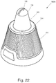
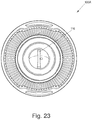
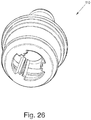
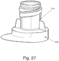
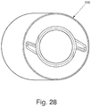
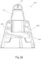
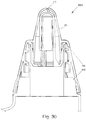
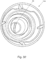
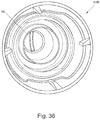
- a dispensing closure for squeeze-type containers is disclosed in Figures 22 to 36 .
- This invention relates to a dispensing closure for dispensing liquid. More specifically, it relates to a dispensing closure defining an exit orifice in the closure to produce a fan-type discharge or spray in a low-pressure environment, as shown in Figures 22 to 36 .
- the present disclosure is generally directed to a dispensing closure for squeeze-type containers.
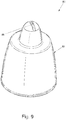
- the dispensing closure 10 has an exit orifice 16 defined in a tip portion 18 of the flow conduit 20.
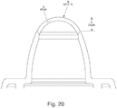
- the tip portion 18 includes a raised non-planar surface which allows for a collection of liquid before discharging liquid in a fan-type spray through the exit orifice 16 in a low-pressure environment.
- a raised spherical surface may be one type of non-planar surface used in the present invention but it is not limited to a raised spherical surface.
- the exit orifice 16 may have a shape other than rectangular depending upon the viscosity of the liquid and desired dimension of the fan-type spray.
- a low pressure environment may be produced by a squeeze-type product container 900 ( Fig. 21 ) upon a force being applied to the product container 900 by a user.
- the fan-type spray is provided at less than 5 psi (34.5 kPa).
- the fan-type spray may be produced between 0.5 psi (3.4 kPa) and 3 psi (20.7 kPa) which is typically the result of an average squeeze produced by a person of average strength.
- each of the embodiments includes a closure body 12 having an upper deck 24 and a skirt 22 depending from the upper deck 24 where the skirt 22 is configured and arranged to attach to a product container 900, such as squeeze-type product container 900 or inverted-type container (not shown).
- the skirt 22 includes internal threads 22A for threaded mounting on an open end or neck of a product container (illustrated in dotted lines).
- skirt mounting arrangements are also contemplated within the scope of the invention, and the invention should not be limited to the inwardly threaded skirt as the singular means for mounting.
- skirt 22 may be a singular or double walled skirt.
- a flow conduit 20 extends from an interior of the closure body 12 and through the upper deck 24 to provide a flow path from an interior of the closure 10 to an exterior of the closure 10.
- the flow conduit 20 has an entrance orifice 20A within the interior of the closure body 12 and an exit orifice 16 outside the exterior of the closure body 12.
- the flow conduit 20 is raised in an elongated manner outside the exterior surface of the body closure 12.
- the flow conduit 20 has an inner wall 21 extending between the entrance orifice 20A and the exit orifice 16.
- the inner wall 21 is gradually inclined to funnel liquid from an interior of the closure body 12 to the tip portion 18.
- a peripheral wall 26 extends upwardly from the upper deck 24 to surround a first body portion 22 of the flow conduit 20 to capture excess liquids.
- the flow conduit 20 includes the tip portion 18 for facilitating the production of a fan-type spray through the exit orifice 16.
- the tip portion 18 includes the raised non-planar surface having an interior volume to collect liquid before the liquid exits through the exit orifice 16 under low pressure. The collection of liquid within an interior volume of the raised non-planar surface provides a continuous and even flow of liquid as it exits through the exit orifice 16.
- the tip portion 18 defines a shape of the exit orifice 16 which facilitates the production of the fan-type spray.
- the dispensing orifice 16 is defined along a diameter of a non-planar surface of the flow conduit 20 and the orifice 16 has a substantially rectangular shape.
- the rectangular exit orifice 16 has a uniform width to provide a uniform thickness and width of the fan-type spray when it exits through the exit orifice 16.
- the exit orifice 16 may also define a uniform width, especially for the rectangular shape, and the tip portion 18 may have a relatively uniform thickness of material.
- the rectangular exit orifice 16 and tip portion 18 having the non-planar surface, disclosed in Figs. 1-3 , are an example and that it is contemplated that other dimensions of the width and depth of the tip portion 18 and a radius of the exit orifice 16 may be adjusted to accommodate varying viscosity of the liquid, desired dimensions of the fan-type spray, and intended purpose of the liquid.
- the dispensing closure 10 can provide a fan-type discharge using multiple configurations of the dispensing orifice 16.
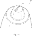
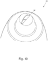
- Other shapes of the exit orifice 16 that may be used are, for example, a bowtie shape ( Fig. 14 ), curved rectangular shape ( Fig. 15 ), dumbbell shape ( Fig. 16 ), half bowtie shape ( Fig. 17 ), keyhole shape ( Fig. 18 ), oval shape ( Fig. 19 ), "J" shape, "T” shape, inverted “T” shape, inverted “J” shape, and other non-circular shapes.
- the bowtie shape ( Fig. 14 ) of the dispensing or exit orifice 16 provides a lighter stream of liquid from the middle of the dispensing orifice 16 and heavier stream of liquid at its ends. This may be particularly desirable for purposes of discharging a toilet blow cleaner inside an interior of a bowl where more liquid may be desirable in an upper lip area and towards the center of the bowl.
- the dispensing orifice may be designed in the shape of a "T", "J", inverted “J”, and inverted “T”. These different configurations provide a lighter stream of liquid from the middle of the dispensing orifice with a heavier stream at a single end.
- the dispensing orifice 16 may also have a non-uniform width along the tip portion 18 of the flow conduit 20.
- the "fan" orifice 16 may have an increased or decreased width of the dispensing orifice 16 depending upon the viscosity of the product and desired angular flow of the liquid.
- the dispensing orifice 16 may extend less than the entire radius or diameter of the non-planar surface area of the tip portion 18.
- the dispensing orifice 16 may be set off its normal orientation, by degrees, in order to provide a better or optimal angle for streaming liquid into a toilet bowl or other desirable environment.
- the fan-type spray from the present invention may be adjusted by using different shapes, sizes, and/or configurations in accordance with those dispensing characteristics desired.
- the flow conduit 20, the closure body 12, and the tip portion 18 are integrally formed to facilitate the fan-type spray in a low pressure environment.
- the flow conduit 20 includes a first body portion 22 of the flow conduit 20 extending from the upper deck 24 to the tip portion 18 in a gradually decreasing diameter.
- the tip portion 18 has a height less than the first body portion 22 of the flow conduit 20 to funnel liquid from an interior of the closure body 12 to the tip portion 18.
- the dispensing closure 10 includes multiple sealing mechanisms to prevent liquid from exiting through the exit orifice 16.
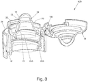
- the dispensing closure 10 includes a closure lid 14, a hinge mechanism 28 for connecting the lid 14 to the body 12, and a latching mechanism 30 for securing the lid 14 to the body 12.
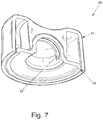
- a sealing wedge 42 is positioned on an interior surface of the lid 44 for sealing engagement through the exit orifice 48 of the flow conduit 50 when the lid 44 is in a closed position to prevent the exit of liquid through the exit orifice 48.
- a sealing member portion 52 of the flow conduit 20 is positioned at an upper portion of the flow conduit 20 for engaging an interior of the closure lid 14 when the lid 14 is in a closed position.
- the interior of the closure lid 14 includes a seal bead 23 to frictionally engage the sealing member portion 52 to prevent the flow of liquid out of the exit orifice 16.
- the sealing member portion 52 includes a seal bead to frictionally engage the interior of the closure lid 14.
- the closure lid 14 includes a mating surface corresponding to an exterior non-planar surface of the tip portion 18. When the lid 14 is in a closed position, the mating surface seals against the tip portion 18 to prevent the flow of liquid through the exit orifice 16 of the flow conduit 20.
- the closure lid 62 includes an inner circular wall 66 depending from a central region.
- the inner circular wall 66 has a diameter to allow for a friction fit with the sealing member portion 68 of the flow conduit 70.
- the inner circular wall 66 snaps over the exit orifice 72 to prevent the exit of liquid therethrough.
- the dispensing closure 80 includes multiple sealing mechanisms to prevent liquid from exiting through the exit orifice 86.
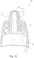
- the dispensing closure 80 includes an insert member 84 positioned within the open end of the product container 900.
- the insert member 84 includes an insert base 88 for seating within the open end of the product container 900.
- the insert member 88 also includes a sealing tube portion 90 extending upwardly from said insert base 88 to occupy an interior volume of the flow conduit 92.
- the sealing tube portion 90 includes a mating surface corresponding to an interior surface of the tip portion 94.
- a sealing member portion 96 of the sealing tube portion 90 is positioned at an upper area of the insert member 84.
- the sealing member portion 96 engages an interior of the flow conduit 92 when the closure body 82 is rotated into in a closed position to contact the sealing tube portion 90.
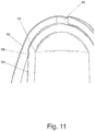
- the interior of the flow conduit 92 includes a seal bead 98 to frictionally engage the sealing member portion 96 to prevent the flow of liquid out of the exit orifice 86.
- the sealing member portion 96 includes the seal bead to frictionally engage the interior of the flow conduit 92. Referring to Figs. 12-13 , when the dispensing closure is rotated into an open position, the closure body 82 disengages from contact with the insert member 88 to allow the flow of liquid through the exit orifice 86.
- the dispensing closure 80 can provide a fan-type discharge using multiple configurations of the dispensing orifice 86.
- Other shapes of the exit orifice 86 that may be used are, for example, a bowtie shape ( Fig. 14 ), curved rectangular shape ( Fig. 15 ), dumbbell shape ( Fig. 16 ), half bowtie shape ( Fig. 17 ), keyhole shape ( Fig. 18 ), oval shape ( Fig. 19 ), "J" shape, "T” shape, inverted “T” shape, inverted “J” shape, and other non-circular shapes
- the dispensing closure 10A, 10B, 40, 60 may have a lid which is attached to the dispensing closure by a hinge mechanism, such as a living hinge.
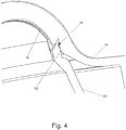
- the dispensing closure 10B may include a latching flange 100 near the hinge mechanism. When the lid 14 is pivoted about the hinge, the latching flange 100 extending from the closure lid 14 may engage a portion of the closure body 12 to facilitate an open position of the lid 14.
- the dispensing closure 10A, 10B, 40, 60 may also include various latching mechanisms for releasably securing the closure lid to the closure body.
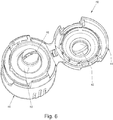
- a dispensing closure is illustrated that includes a child-resistant latching mechanism.
- This latching mechanism features a double-walled skirt having diametrically opposing sides which are depressed, at a lower portion, before opening the closure lid hingedly connected to the closure.
- the dispensing closure disengages the lid from the closure body by pushing inwardly on the outer side wall of the skirt to move hook members on the closure body away from hook members on the closure lid and away from a central axis of the dispensing closure.
- a single latching mechanism may also be used as shown in Fig. 5 . It should be noted that Figs. 1-8 show an example of one type of hinge mechanism and latching mechanism and that other types of lid configurations may be used in the present invention.
- the dispensing closure 60 of provides a fan-type spray or stream of liquid that fans out in a low pressure environment when the product container is squeezed.
- any of the embodiments of the dispensing closure may be attached to the product container and this is merely an example.
- the low pressure environment may be less than 5psi (34.5 kPa).
- the dispensing closure is attached to a squeeze-type product container.
- the liquid within the container moves through the flow conduit, collects within the tip portion to decelerate the velocity of the liquid, and discharges through the fan-type shaped exit orifice in a fan-type spray at less than 5 psi (34.5 kPa).
- the dispensing closure provides a stream of liquid that fans out when the product container is squeezed.
- the purpose of the fan-type discharge is to provide a person who is cleaning, for example, a toilet bowl a wide stream of liquid to cover the desired portions of the bowl.
- the flow path and velocity of the liquid through the dispensing closure during operation provides a fan-type spray in a low-pressure environment.
- the liquid moves from an interior of the product container and into an interior of the dispensing closure attached to the product container.
- the liquid then accelerates into the flow conduit.
- the flow conduit has a gradually decreasing diameter which funnels the liquid into the tip portion where it temporarily collects or pools in the interior volume of the raised non-planar surface.
- the purpose of the raised non-planar surface is to maintain a continuous flow of the liquid discharge while it exits through the shaped exit orifice in a fan-type discharge.
- the dispensing closure with the closure lid operates in the following manner.
- the user depresses the sides of the closure body to release the closure lid whereby the closure lid is moved into an open position.
- the user snappingly engages the lid over the closure body.
- the dispensing closure with the insert member operates in the following manner.
- a user rotates or turns the closure body relative to the stationary insert member to remove the sealing tube away from sealing engagement with the exit orifice.
- the user squeezes the product container to discharge liquid through the exit orifice in a fan-type spray.
- the user rotates or turns the closure body relative to the stationary insert member to return the sealing tube in sealing engagement with the exit orifice.
- the dimensions and shape of the dispensing closure, flow conduit, tip portion, and exit orifice are adjustable depending upon the viscosity of the product stored within an interior of the product container.
- a tip portion which defines a width (A), depth (C), and radius (B) of said exit orifice which are adjustable according to the viscosity of the liquid and desired dimension of the fan-type discharge. For example, for a low viscosity liquid, it may be desirable for a flow conduit with smaller dimension to achieve a lower flow volume. Conversely, it may be desirable for a flow conduit with large dimensions for a highly viscous product to achieve a higher flow volume.
- a dispensing closure is provided related to container closures, and more particularly to squeeze-type container dispensing closures.
- This invention relates to a dispensing closure for dispensing liquid with varying degrees of viscosity. More specifically, it relates to a dispensing closure defining an orifice in the closure to produce a fan-type discharge or spray in a low-pressure environment.
- a two-piece dispensing closure 100A, 100B incorporates the advantages and benefits of the above-mentioned dispensing closures 10A, 10B, 40, 60, 80 ( Figs. 1-21 ) defining an exit orifice 116 to produce a fan-type discharge or spay in a low-pressure environment.
- the two-piece dispensing closures 100A, 100B further include two pairs of opposing stopping tabs which cooperate with a single pair of opposed stopping lugs on a neck 910 of a container 900 to provide a child-resistant mechanism, which are further explained herein.
- the present invention is generally directed to a novel dispensing closure for squeeze-type containers.
- the dispensing closure 100A, 100B has an exit orifice 116 defined in a tip portion 118 of the flow conduit 120.
- the tip portion 118 includes a raised non-planar surface which allows for a collection of liquid before discharging liquid in a fan-type spray through the exit orifice 116 in a low-pressure environment.
- the dispensing closure 100A, 100B includes a closure body 102 having an upper deck 124 and a skirt 122 depending from the upper deck 124 where the skirt 122A, 122B is configured and arranged to attach to a product container 900, such as squeeze-type product container 900 or inverted-type container (not shown).
- a product container 900 such as squeeze-type product container 900 or inverted-type container (not shown).
- the skirt 122A, 122B includes threads 123A, 123B for threaded mounting on an open end or neck of a product container.
- a flow conduit 120 extends from an interior of the closure body 102 and through the upper deck 124 to provide a flow path from an interior of the closure 100A, 100B to an exterior of the closure 100A, 100B.
- the flow conduit 120 has an entrance orifice 120A within the interior of the closure body 102 and an exit orifice 106 outside the exterior of the closure body 102.
- the flow conduit 120 is raised in an elongated manner outside the exterior surface of the closure body 102.
- the flow conduit 120 has an inner wall 121 extending between the entrance orifice 120A and the exit orifice 116.
- the inner wall 121 is inclined to funnel liquid from an interior of the closure body 102 to the tip portion 118.
- the flow conduit 120 includes the tip portion 118 for facilitating the production of a fan-type spray through the exit orifice 116.
- the tip portion 118 includes the raised non-planar surface having an interior volume to collect liquid before the liquid exits through the exit orifice 116 under low pressure. The collection of liquid within an interior volume of the raised non-planar surface provides a continuous and even flow of liquid as it exits through the exit orifice 116.
- the tip portion 118 defines a shape of the exit orifice 116 which facilitates the production of the fan-type spray.
- the exit orifice 116 is defined along a diameter of a non-planar surface of the flow conduit 120 and the orifice 116 has a substantially rectangular shape.
- the rectangular exit orifice 16 has a non-uniform width to provide a non-uniform thickness and width of the fan-type spray when it exits through the exit orifice 116.
- the exit orifice 116 may also define a uniform width, especially for the rectangular shape, and the tip portion 118 may have a relatively uniform thickness of material.
- the dispensing closure 100 includes multiple sealing mechanisms similar to those disclosed in dispensing closure 80 to prevent liquid from exiting through the exit orifice 106.
- the dispensing closure 110 includes the insert member 110 positioned within the open end of the product container 900.
- the insert member 110 includes an insert base for seating within the open end of the product container 900.
- the insert member 110 also includes a sealing tube portion 111 extending upwardly from the insert base to occupy an interior volume of the flow conduit 120.
- the sealing tube portion 111 includes a mating surface corresponding to an interior surface of the tip portion 118.
- a sealing member portion of the sealing tube portion 11 is positioned at an upper area of the insert member 110.
- the sealing member portion engages an interior of the flow conduit 120 when the closure body 102 is rotated into in a closed position to contact the sealing tube portion 111.
- the interior of the flow conduit includes a seal bead to frictionally engage the sealing member portion to prevent the flow of liquid out of the exit orifice 106.
- the sealing member portion includes the seal bead to frictionally engage the interior of the flow conduit 120.
- the dispensing closure 100A, 100B includes a threaded container finish or neck 910, an insert member 110 received inside the opening of the container finish, with the dispensing closure 100A, 100B threadably received on the container neck 910 so that the dispensing closure is rotatable from a closed position to an open position.
- the dispensing closure 100A, 100B includes a flow conduit 120 with a rectangular slit-shaped orifice 116 effective for spraying a fan shaped pattern of liquid.
- the insert member 110 includes a sealing tube portion 111, which is positioned so that the opening in tip of the flow conduit 120 is sealed by the sealing tube portion 111 when the dispensing closure 100A, 100B is in the closed position.
- the dispensing closure 100A is illustrated as assembled and attached to neck of the container.
- the interference or engagement between the outer diameter of the insert member 110 and the inner diameter of the neck 910 may tend to spread out of the outer diameter of the neck of the bottle. This spreading out of the neck may over time continue to relax thereby reducing the interference or engagement which could result in an insert staying with a dispensing closure when it is opened instead of the bottle neck.
- This capture ring 150 captures or holds the bottle neck and insert member in place which minimizes the initial spreading and stops any post relaxation.
- the capture ring 150 maintains contact with the bottle neck and inserts member outer diameter allowing seal surfaces to break free from insert member forcing it to stay within the bottle neck.
- the first sealing mechanism is totally disengaged before capture ring is moved up far enough to be released from the insert and bottle outer diameter.
- the outer diameter of the insert member may be reduced to facilitate operation of the capture ring.
- the dispensing closure 100A, 100B generally includes an upper wall from which the flow conduit projects upwardly and an inner wall extending downwardly from the upper wall.
- the inner wall is threadably received onto the container neck.
- the dispensing closure includes an outer shell wall or skirt depending downwardly and outwardly from the upper wall.
- the threads of the container neck and inner wall of the dispensing closure are a double thread design where the cap can be moved from a fully closed position to an operative open position by rotation of approximately 90 degrees. Complete removal of the dispensing closure from the neck requires a rotation of more than 270 degrees from fully engaged to fully disengaged.
- the dispensing closure 100A, 100B also includes two pairs of opposing stopping tabs on the inner surface of the outer wall, which cooperate with a single pair of opposed stopping lugs on the container finish.
- a first, opposed pair of stopping tabs function as child resistant latches to resist movement of the dispensing closure from the closed position to the open position.
- the dispensing closure must be squeezed at opposing locations (identified with thumb pads) on the dispensing closure to deform the dispensing closure and move the CR tabs outwardly to overcome the stop lugs. Once freed from the stop lugs, the dispensing closure can then rotate 90 degrees where the second set of stopping tabs engages with the stop lugs to prevent further rotation. This second set of stopping tabs prevents complete removal of the dispensing closure from the container finish.
- the dispensing closure 110A, 110B can provide a fan-type discharge using multiple configurations of the dispensing orifice 106 other than substantially rectangular.
- Other shapes of the exit orifice 106 that may be used are, for example, a bowtie shape ( Fig. 14 ), curved rectangular shape ( Fig. 15 ), dumbbell shape ( Fig. 16 ), half bowtie shape ( Fig. 17 ), keyhole shape ( Fig. 18 ), oval shape ( Fig. 19 ), "J" shape, "T” shape, inverted “T” shape, inverted “J” shape, and other non-circular shapes.
Landscapes
- Engineering & Computer Science (AREA)
- Mechanical Engineering (AREA)
- Closures For Containers (AREA)
- Infusion, Injection, And Reservoir Apparatuses (AREA)
Claims (4)
- Système de bouchon de distribution (100A ; 100B) comprenant :un récipient compressible (900) ayant un col fileté (910) ;un élément formant insert (110) comportant :une base configurée et agencée pour être mise en appui dans ledit col fileté (910) dudit récipient compressible (900) ; etun tube d'étanchéité (111) s'étendant vers le haut depuis ladite base, ledit tube d'étanchéité ayant une partie d'élément d'étanchéité à une extrémité supérieure de celui-ci ;un corps de bouchon (102) comportant :un étage supérieur (124) ;une jupe (122, 122A ; 122B) en prolongement vers le bas depuis ledit étage supérieur (124), la jupe (122, 122A ; 122B) comportant des filets (123A, 123B) sur une surface interne configurés et agencés pour se mettre en prise de façon vissée avec ledit col fileté (910), ledit corps de bouchon (102) étant mobile de manière rotative par rapport audit col fileté ; etun conduit d'écoulement (120) s'étendant vers le haut depuis ledit étage supérieur (124) pour fournir un chemin d'écoulement d'une partie intérieure dudit corps de bouchon vers une partie extérieure dudit corps de bouchon, ledit conduit d'écoulement (120) ayant une partie d'embout de distribution (118), ledit conduit d'écoulement comportant un orifice d'entrée (120A) et un orifice de sortie (116) au niveau de ladite partie d'embout de distribution (118), ledit conduit d'écoulement (120) ayant une paroi intérieure (121) s'étendant entre ledit orifice d'entrée (120A) et ledit orifice de sortie (116) ;ledit corps de bouchon (102) étant mobile par rapport à ladite base entre une position fermée dans laquelle ladite partie d'élément d'étanchéité dudit tube d'étanchéité se met en contact par accouplement avec ladite paroi intérieure (121) dudit conduit d'écoulement dans la région de ladite partie d'embout de distribution (118) et empêche un écoulement de liquide de sortir par ledit orifice de sortie (116), et une position ouverte dans laquelle ladite paroi intérieure (121) dudit conduit d'écoulement (120) dans la région de ladite partie d'embout de distribution (118) est espacée de ladite partie d'élément d'étanchéité dudit tube d'étanchéité (111) et permet à un écoulement de fluide de sortir par ledit orifice de sortie (116), ledit orifice de sortie (116) étant configuré et agencé pour produire un refoulement en forme d'éventail quand on retourne et que l'on presse ledit récipient de type compressible, et ladite partie d'embout de distribution (118) ayant une surface non plane ayant un volume intérieur pour collecter un liquide avant que le liquide ne sorte par ledit orifice de sortie (116) à moins de 34,5 kPa (5 psi),caractérisé en ce que le récipient compressible (900) comprend : une paire simple d'oreilles d'arrêt symétriquement opposées, voisine dudit col fileté (910) du récipient compressible, ladite jupe (122) comporte en outre une partie inférieure flexible avec des première et deuxième paires opposées de pattes d'arrêt situées sur celle-ci, ladite première paire de pattes d'arrêt étant destinée à se mettre en prise avec lesdites oreilles d'arrêt sur ledit col fileté (910) quand ledit corps de bouchon (102) est dans ladite position fermée, ladite première paire de pattes d'arrêt empêchant la rotation dudit corps de bouchon (102) depuis ladite position fermée, sauf si ladite partie inférieure flexible de ladite jupe (122, 122A, 122B) est pressée vers l'intérieur en des endroits opposés décalés par rapport auxdites premières pattes d'arrêt pour déformer ladite partie inférieure de la jupe et déplacer ladite première paire de pattes d'arrêt vers l'extérieur au-delà desdites oreilles d'arrêt, ladite deuxième paire de pattes d'arrêt se mettant en prise avec lesdites oreilles d'arrêt pour immobiliser ledit corps de bouchon (102) dans ladite position ouverte et empêcher le retrait complet dudit corps de bouchon dudit col ; et en ce qu'une partie supérieure de la surface interne de la jupe (122, 122A, 122B) sous ledit étage supérieur (124) comprend une bague de retenue (150) configurée et agencée pour maintenir en place le col fileté (910) du récipient compressible (900) et l'élément formant insert (110), moyennant quoi, après l'ouverture initiale du bouchon de distribution, la bague de retenue (150) maintient le contact avec le col fileté (910) du récipient compressible (900) et le diamètre extérieur de l'élément formant insert (110), en permettant aux surfaces d'étanchéité du corps de bouchon (102) de se dégager de l'élément formant insert (110), et en forçant l'élément formant insert à rester dans le col fileté.
- Bouchon de distribution selon la revendication 1, dans lequel ladite surface non plane est une surface extérieure semi-sphérique.
- Bouchon de distribution selon la revendication 1 ou 2, dans lequel ledit orifice de sortie (116) a une forme choisie dans un groupe comprenant : une forme rectangulaire, nœud papillon, demi nœud papillon, ovale, trou de serrure, haltère, rectangulaire courbée, en « J », en « T », en « T » inversé, en « J » inversé, et autres formes non circulaires.
- Bouchon de distribution selon la revendication 1, 2 ou 3, dans lequel ladite paroi intérieure (121) dudit conduit d'écoulement (120) comporte un bourrelet d'étanchéité qui se met en prise avec frottement avec ladite partie d'élément d'étanchéité dudit tube d'étanchéité (111).
Applications Claiming Priority (2)
| Application Number | Priority Date | Filing Date | Title |
|---|---|---|---|
| US13/178,385 US8814010B2 (en) | 2008-06-18 | 2011-07-07 | Fan orifice dispensing closure |
| PCT/US2012/045440 WO2013012558A1 (fr) | 2011-07-07 | 2012-07-03 | Fermeture de distribution d'orifice en éventail |
Publications (3)
| Publication Number | Publication Date |
|---|---|
| EP2729257A1 EP2729257A1 (fr) | 2014-05-14 |
| EP2729257A4 EP2729257A4 (fr) | 2015-03-25 |
| EP2729257B1 true EP2729257B1 (fr) | 2021-01-20 |
Family
ID=47558984
Family Applications (1)
| Application Number | Title | Priority Date | Filing Date |
|---|---|---|---|
| EP12815592.6A Active EP2729257B1 (fr) | 2011-07-07 | 2012-07-03 | Fermeture de distribution d'orifice en éventail |
Country Status (7)
| Country | Link |
|---|---|
| US (2) | US8814010B2 (fr) |
| EP (1) | EP2729257B1 (fr) |
| CN (1) | CN103842093B (fr) |
| BR (1) | BR112014000261B1 (fr) |
| CA (1) | CA2840952C (fr) |
| MX (1) | MX353644B (fr) |
| WO (1) | WO2013012558A1 (fr) |
Families Citing this family (13)
| Publication number | Priority date | Publication date | Assignee | Title |
|---|---|---|---|---|
| US10549289B2 (en) * | 2008-06-18 | 2020-02-04 | Silgan Dispensing Systems Slatersville, Llc | Fan orifice dispensing closure |
| US8469241B2 (en) * | 2008-06-18 | 2013-06-25 | Mwv Slatersville, Llc | Fan orifice dispensing closure |
| GB2519206B (en) * | 2013-08-17 | 2015-11-25 | Mwv Slatersville Llc | One-piece squeeze-to-dose dispensing closure |
| USD787327S1 (en) * | 2014-02-04 | 2017-05-23 | Ampac Holdings, Llc | Flip top cap |
| USD749950S1 (en) * | 2014-02-04 | 2016-02-23 | Ampac Holdings, Llc | Flip top cap |
| GB201402765D0 (en) * | 2014-02-17 | 2014-04-02 | Carbonite Corp | Dispensers for viscous or pasty materials |
| MX2017017012A (es) * | 2015-06-26 | 2018-08-15 | Oil & Gas Tech Entpr C V | Montajes de boquilla de lavado de generacion de vortice. |
| US11064711B2 (en) | 2015-08-27 | 2021-07-20 | Societe Des Produits Nestle S.A. | Closures for liquid-dispensing containers and methods for making and using such closures |
| GB201600894D0 (en) * | 2016-01-18 | 2016-03-02 | Obrist Closures Switzerland | Dispensing closure |
| WO2019113681A1 (fr) | 2017-12-15 | 2019-06-20 | Husky Injection Molding Systems Ltd. | Capuchon de fermeture destiné à un récipient |
| USD980069S1 (en) | 2020-07-14 | 2023-03-07 | Ball Corporation | Metallic dispensing lid |
| US12582999B2 (en) * | 2020-12-18 | 2026-03-24 | 3M Innovative Properties Company | Two-fluid nozzle with an arcuate opening |
| US12168551B2 (en) | 2021-03-01 | 2024-12-17 | Ball Corporation | Metal container and end closure with seal |
Family Cites Families (55)
| Publication number | Priority date | Publication date | Assignee | Title |
|---|---|---|---|---|
| US1739871A (en) * | 1926-11-15 | 1929-12-17 | Arthur E Smith | Receptacle closure |
| US2135237A (en) * | 1938-05-07 | 1938-11-01 | Helen P Lewis | Closure for containers |
| US2759643A (en) | 1951-02-01 | 1956-08-21 | Orga Ab | Container closure |
| US2755137A (en) | 1953-06-24 | 1956-07-17 | Geo Bray And Company Ltd | Liquid spray jets |
| US3877598A (en) | 1974-02-25 | 1975-04-15 | Polytop Corp | Closure structures having child-safety feature |
| US4175704A (en) | 1976-02-17 | 1979-11-27 | Cohen Milton J | Non-aerosol continuous spray dispenser |
| US4022352A (en) | 1976-04-26 | 1977-05-10 | Pehr Harold T | Container cover and safety closure |
| US4109869A (en) | 1977-06-16 | 1978-08-29 | Dutton-Lainson Company | Oiler with adjustable spray nozzle |
| US4377247A (en) | 1978-10-31 | 1983-03-22 | Polytop Corporation | Dispensing closure employing living hinge |
| US4420100A (en) | 1978-10-31 | 1983-12-13 | Containaire, Inc. | Dispensing apparatus |
| DE8235857U1 (de) * | 1982-12-21 | 1984-05-24 | Wella Ag, 6100 Darmstadt | Selbsttaetiger Verschluss fuer flexible Behaelter |
| US4760956A (en) | 1986-07-14 | 1988-08-02 | Glas-Craft, Inc. | Internal mix plural component system |
| US4718607A (en) | 1986-07-30 | 1988-01-12 | Acheson Industries, Inc. | Atomized liquid spray orifice |
| US4971256A (en) | 1988-10-04 | 1990-11-20 | Malcolm William R | Sprinkler device |
| US5005737A (en) * | 1989-06-29 | 1991-04-09 | Seaquist Closures | Flexible dispensing closure having a slitted resilient outlet valve and a flanged vent valve |
| US5040950A (en) | 1989-08-07 | 1991-08-20 | Northland Aluminum Products, Inc. | Power washing apparatus |
| IT1240860B (it) | 1990-01-23 | 1993-12-17 | Taplast Snc Di Evans Santagiuliana & C. | Nebulizzatore |
| US5639025A (en) | 1995-07-07 | 1997-06-17 | The Procter & Gamble Company | High Viscosity pump sprayer utilizing fan spray nozzle |
| US5642860A (en) | 1995-07-07 | 1997-07-01 | The Procter & Gamble Company | Pump sprayer for viscous or solids laden liquids |
| US5664732A (en) | 1995-08-16 | 1997-09-09 | Owens-Illinois Closure Inc. | Nozzle for pump dispensers |
| US5692682A (en) | 1995-09-08 | 1997-12-02 | Bete Fog Nozzle, Inc. | Flat fan spray nozzle |
| US5605257A (en) * | 1996-03-04 | 1997-02-25 | Beard; Walter C. | Sterile liquid squeeze-bottle-type dispenser |
| GB9605569D0 (en) | 1996-03-16 | 1996-05-15 | Reckitt & Colman Inc | Improved packaging |
| FR2747373B1 (fr) * | 1996-04-16 | 1998-06-05 | Oreal | Distributeur pour un produit de consistance non compacte |
| US5927566A (en) | 1996-07-11 | 1999-07-27 | Aptargroup, Inc. | One-piece dispensing system and method for making same |
| US5890655A (en) | 1997-01-06 | 1999-04-06 | The Procter & Gamble Company | Fan spray nozzles having elastomeric dome-shaped tips |
| FR2758801B1 (fr) | 1997-01-27 | 1999-03-26 | Valois | Systeme d'obturation d'un dispositif de distribution de produit fluide |
| FR2761281B1 (fr) | 1997-03-26 | 1999-05-21 | Valois Sa | Dispositif de pulverisation de produit fluide, tel q'un bidose |
| FR2768409B1 (fr) | 1997-09-17 | 1999-10-15 | Oreal | Ensemble de conditionnement et de distribution d'un produit liquide ou semi liquide |
| EP0911616B1 (fr) | 1997-10-27 | 2001-08-29 | Alpla Werke Alwin Lehner GmbH & CO. KG | Bouteille, en particulier pour nettoyer des cuvettes de w.c. |
| FR2771078B1 (fr) * | 1997-11-14 | 2000-01-28 | Oreal | Organe reducteur d'ecoulement, notamment pour un recipient contenant un produit cosmetique et procede de fabrication |
| US6065651A (en) * | 1998-08-24 | 2000-05-23 | Kraft Foods, Inc. | Closable dispenser and dispensing apparatus |
| US6460787B1 (en) | 1998-10-22 | 2002-10-08 | Nordson Corporation | Modular fluid spray gun |
| US5967377A (en) | 1999-03-25 | 1999-10-19 | Primary Delivery Systems, Inc. | Metered liquid dispenser with lift fill mechanism |
| US6176399B1 (en) | 1999-07-12 | 2001-01-23 | Aptargroup, Inc | Valved dispensing system for multiple dispensing streams |
| US6623201B2 (en) | 2000-09-08 | 2003-09-23 | John Francois Brumlik | Cleaning device and method of use |
| US6698605B2 (en) | 2001-05-21 | 2004-03-02 | Rexam Medical Packaging Inc. | Modified bottle neck for use with child resistant caps |
| FR2830240B1 (fr) * | 2001-10-01 | 2004-08-20 | Oreal | Dispositif de conditionnement d'un produit, notamment un produit cosmetique et/ou de soins |
| US6659369B1 (en) | 2002-06-12 | 2003-12-09 | Continental Afa Dispensing Company | High viscosity liquid sprayer nozzle assembly |
| US6662973B1 (en) * | 2002-07-02 | 2003-12-16 | Stephen P. Velliquette | Fluid flow control valve/seal for fluid dispensers |
| WO2004043820A1 (fr) | 2002-11-11 | 2004-05-27 | Gefit S.P.A. | Systeme de fermeture pour receptacle et son procede de fabrication |
| ITRM20030055A1 (it) * | 2003-02-10 | 2004-08-11 | Emsar Spa | Testa erogatrice a nebulizzazione per flacone deformabile elasticamente per schiacciamento. |
| FR2857342B1 (fr) | 2003-07-10 | 2008-03-28 | Valois Sas | Tete de distribution de produit fluide |
| FR2863595B1 (fr) | 2003-12-12 | 2006-03-03 | Airlessystems | Distributeur de produit fluide. |
| US7124962B1 (en) | 2005-05-24 | 2006-10-24 | S.C. Johnson & Son, Inc. | Sprayer for cleaning exterior surfaces |
| US20060273195A1 (en) | 2005-06-03 | 2006-12-07 | Eric Junkel | Portable misting fan with closely integrated pump |
| US7854336B2 (en) * | 2005-07-05 | 2010-12-21 | Jordan Kerner | Beverage dispenser having an airtight valve and seal |
| US20070295762A1 (en) | 2006-04-25 | 2007-12-27 | Lifetime Brands, Inc. | Easy-open dispensing cap |
| US7828166B1 (en) * | 2006-05-03 | 2010-11-09 | Rexam Closures And Containers Inc. | Dispensing closure with child resistant feature |
| US7543724B2 (en) | 2006-06-21 | 2009-06-09 | Seaquist Closures Foreign, Inc. | Dispensing system with a dispensing valve having a projecting, reduced size discharge end |
| US20070295764A1 (en) | 2006-06-21 | 2007-12-27 | Socier Timothy R | Flexible, elongate dispensing valve |
| US7648051B1 (en) * | 2006-08-09 | 2010-01-19 | Rexam Closures And Containers Inc. | Double shell dispensing closure with a reverse tapered drop lug |
| EP2074053B1 (fr) * | 2006-09-01 | 2014-11-12 | MWV Slatersville, LLC. | Fermeture de distribution |
| US7980432B2 (en) * | 2006-09-01 | 2011-07-19 | Polytop Corporation | Dispensing closure having a flow conduit with key-hole shape |
| US8469241B2 (en) * | 2008-06-18 | 2013-06-25 | Mwv Slatersville, Llc | Fan orifice dispensing closure |
-
2011
- 2011-07-07 US US13/178,385 patent/US8814010B2/en active Active
-
2012
- 2012-07-03 EP EP12815592.6A patent/EP2729257B1/fr active Active
- 2012-07-03 MX MX2014000228A patent/MX353644B/es active IP Right Grant
- 2012-07-03 CA CA2840952A patent/CA2840952C/fr active Active
- 2012-07-03 BR BR112014000261-4A patent/BR112014000261B1/pt active IP Right Grant
- 2012-07-03 WO PCT/US2012/045440 patent/WO2013012558A1/fr not_active Ceased
- 2012-07-03 CN CN201280043788.3A patent/CN103842093B/zh active Active
-
2014
- 2014-08-22 US US14/466,324 patent/US10406536B2/en active Active
Non-Patent Citations (1)
| Title |
|---|
| None * |
Also Published As
| Publication number | Publication date |
|---|---|
| US10406536B2 (en) | 2019-09-10 |
| MX353644B (es) | 2018-01-22 |
| BR112014000261A2 (pt) | 2017-02-14 |
| US20120000944A1 (en) | 2012-01-05 |
| US20140361050A1 (en) | 2014-12-11 |
| CA2840952C (fr) | 2014-12-09 |
| WO2013012558A1 (fr) | 2013-01-24 |
| BR112014000261B1 (pt) | 2021-01-19 |
| CN103842093B (zh) | 2017-12-08 |
| US8814010B2 (en) | 2014-08-26 |
| EP2729257A1 (fr) | 2014-05-14 |
| MX2014000228A (es) | 2015-01-14 |
| EP2729257A4 (fr) | 2015-03-25 |
| CA2840952A1 (fr) | 2013-01-24 |
| CN103842093A (zh) | 2014-06-04 |
Similar Documents
| Publication | Publication Date | Title |
|---|---|---|
| EP2729257B1 (fr) | Fermeture de distribution d'orifice en éventail | |
| US10940494B2 (en) | Fan orifice dispensing closure | |
| US10549289B2 (en) | Fan orifice dispensing closure | |
| AU758975B2 (en) | Valved dispensing system for multiple dispensing streams | |
| US7784652B2 (en) | Dispensing valve with hydraulic hammer resistance | |
| US20060060618A1 (en) | Multiple lid closure with open lid retention feature | |
| US5842618A (en) | Dispensing closure with controlled valve actuation | |
| AU2005301278B2 (en) | Child-resistant dispensing closure, package and method of manufacture | |
| JPS61502239A (ja) | 摺動自在なトリガ−を有するポンプディスペンサ− | |
| US3131870A (en) | Spray nozzle with tethered closure | |
| US4813577A (en) | Multiple flow dispensing cap | |
| US7036689B1 (en) | Child-resistant trigger sprayer | |
| GB2284202A (en) | Spray type valved dispenser cap | |
| GB2196062A (en) | Actuator caps for pressurised dispensers |
Legal Events
| Date | Code | Title | Description |
|---|---|---|---|
| PUAI | Public reference made under article 153(3) epc to a published international application that has entered the european phase |
Free format text: ORIGINAL CODE: 0009012 |
|
| 17P | Request for examination filed |
Effective date: 20140102 |
|
| AK | Designated contracting states |
Kind code of ref document: A1 Designated state(s): AL AT BE BG CH CY CZ DE DK EE ES FI FR GB GR HR HU IE IS IT LI LT LU LV MC MK MT NL NO PL PT RO RS SE SI SK SM TR |
|
| RIN1 | Information on inventor provided before grant (corrected) |
Inventor name: BRANNON, PATRICK Inventor name: SKILLIN, CLIFFORD Inventor name: ROMANOV, SERGEY |
|
| DAX | Request for extension of the european patent (deleted) | ||
| A4 | Supplementary search report drawn up and despatched |
Effective date: 20150219 |
|
| RIC1 | Information provided on ipc code assigned before grant |
Ipc: B05B 11/04 20060101ALI20150213BHEP Ipc: B65D 47/06 20060101ALI20150213BHEP Ipc: B05B 11/00 20060101ALI20150213BHEP Ipc: B65D 50/04 20060101AFI20150213BHEP Ipc: B05B 1/34 20060101ALI20150213BHEP Ipc: B05B 1/04 20060101ALI20150213BHEP Ipc: B65D 47/24 20060101ALI20150213BHEP Ipc: B65D 47/08 20060101ALN20150213BHEP |
|
| RAP1 | Party data changed (applicant data changed or rights of an application transferred) |
Owner name: WESTROCK SLATERSVILLE, LLC |
|
| RAP1 | Party data changed (applicant data changed or rights of an application transferred) |
Owner name: SILGAN DISPENSING SYSTEMS SLATERSVILLE LLC |
|
| STAA | Information on the status of an ep patent application or granted ep patent |
Free format text: STATUS: EXAMINATION IS IN PROGRESS |
|
| 17Q | First examination report despatched |
Effective date: 20180709 |
|
| REG | Reference to a national code |
Ref country code: DE Ref legal event code: R079 Ref document number: 602012074240 Country of ref document: DE Free format text: PREVIOUS MAIN CLASS: B05B0001340000 Ipc: B65D0050040000 |
|
| GRAP | Despatch of communication of intention to grant a patent |
Free format text: ORIGINAL CODE: EPIDOSNIGR1 |
|
| STAA | Information on the status of an ep patent application or granted ep patent |
Free format text: STATUS: GRANT OF PATENT IS INTENDED |
|
| INTG | Intention to grant announced |
Effective date: 20200731 |
|
| RIC1 | Information provided on ipc code assigned before grant |
Ipc: B65D 50/04 20060101AFI20200717BHEP Ipc: B05B 1/04 20060101ALI20200717BHEP Ipc: B05B 11/00 20060101ALI20200717BHEP Ipc: B65D 47/08 20060101ALN20200717BHEP Ipc: B05B 11/04 20060101ALI20200717BHEP Ipc: B05B 1/34 20060101ALI20200717BHEP Ipc: B65D 47/06 20060101ALI20200717BHEP Ipc: B65D 47/24 20060101ALI20200717BHEP |
|
| GRAS | Grant fee paid |
Free format text: ORIGINAL CODE: EPIDOSNIGR3 |
|
| GRAA | (expected) grant |
Free format text: ORIGINAL CODE: 0009210 |
|
| STAA | Information on the status of an ep patent application or granted ep patent |
Free format text: STATUS: THE PATENT HAS BEEN GRANTED |
|
| AK | Designated contracting states |
Kind code of ref document: B1 Designated state(s): AL AT BE BG CH CY CZ DE DK EE ES FI FR GB GR HR HU IE IS IT LI LT LU LV MC MK MT NL NO PL PT RO RS SE SI SK SM TR |
|
| REG | Reference to a national code |
Ref country code: GB Ref legal event code: FG4D |
|
| REG | Reference to a national code |
Ref country code: CH Ref legal event code: EP |
|
| REG | Reference to a national code |
Ref country code: AT Ref legal event code: REF Ref document number: 1356199 Country of ref document: AT Kind code of ref document: T Effective date: 20210215 |
|
| REG | Reference to a national code |
Ref country code: IE Ref legal event code: FG4D |
|
| REG | Reference to a national code |
Ref country code: DE Ref legal event code: R096 Ref document number: 602012074240 Country of ref document: DE |
|
| REG | Reference to a national code |
Ref country code: NL Ref legal event code: MP Effective date: 20210120 |
|
| REG | Reference to a national code |
Ref country code: LT Ref legal event code: MG9D |
|
| REG | Reference to a national code |
Ref country code: AT Ref legal event code: MK05 Ref document number: 1356199 Country of ref document: AT Kind code of ref document: T Effective date: 20210120 |
|
| PG25 | Lapsed in a contracting state [announced via postgrant information from national office to epo] |
Ref country code: FI Free format text: LAPSE BECAUSE OF FAILURE TO SUBMIT A TRANSLATION OF THE DESCRIPTION OR TO PAY THE FEE WITHIN THE PRESCRIBED TIME-LIMIT Effective date: 20210120 Ref country code: GR Free format text: LAPSE BECAUSE OF FAILURE TO SUBMIT A TRANSLATION OF THE DESCRIPTION OR TO PAY THE FEE WITHIN THE PRESCRIBED TIME-LIMIT Effective date: 20210421 Ref country code: HR Free format text: LAPSE BECAUSE OF FAILURE TO SUBMIT A TRANSLATION OF THE DESCRIPTION OR TO PAY THE FEE WITHIN THE PRESCRIBED TIME-LIMIT Effective date: 20210120 Ref country code: PT Free format text: LAPSE BECAUSE OF FAILURE TO SUBMIT A TRANSLATION OF THE DESCRIPTION OR TO PAY THE FEE WITHIN THE PRESCRIBED TIME-LIMIT Effective date: 20210520 Ref country code: LT Free format text: LAPSE BECAUSE OF FAILURE TO SUBMIT A TRANSLATION OF THE DESCRIPTION OR TO PAY THE FEE WITHIN THE PRESCRIBED TIME-LIMIT Effective date: 20210120 Ref country code: BG Free format text: LAPSE BECAUSE OF FAILURE TO SUBMIT A TRANSLATION OF THE DESCRIPTION OR TO PAY THE FEE WITHIN THE PRESCRIBED TIME-LIMIT Effective date: 20210420 Ref country code: NL Free format text: LAPSE BECAUSE OF FAILURE TO SUBMIT A TRANSLATION OF THE DESCRIPTION OR TO PAY THE FEE WITHIN THE PRESCRIBED TIME-LIMIT Effective date: 20210120 Ref country code: NO Free format text: LAPSE BECAUSE OF FAILURE TO SUBMIT A TRANSLATION OF THE DESCRIPTION OR TO PAY THE FEE WITHIN THE PRESCRIBED TIME-LIMIT Effective date: 20210420 |
|
| PG25 | Lapsed in a contracting state [announced via postgrant information from national office to epo] |
Ref country code: AT Free format text: LAPSE BECAUSE OF FAILURE TO SUBMIT A TRANSLATION OF THE DESCRIPTION OR TO PAY THE FEE WITHIN THE PRESCRIBED TIME-LIMIT Effective date: 20210120 Ref country code: LV Free format text: LAPSE BECAUSE OF FAILURE TO SUBMIT A TRANSLATION OF THE DESCRIPTION OR TO PAY THE FEE WITHIN THE PRESCRIBED TIME-LIMIT Effective date: 20210120 Ref country code: PL Free format text: LAPSE BECAUSE OF FAILURE TO SUBMIT A TRANSLATION OF THE DESCRIPTION OR TO PAY THE FEE WITHIN THE PRESCRIBED TIME-LIMIT Effective date: 20210120 Ref country code: RS Free format text: LAPSE BECAUSE OF FAILURE TO SUBMIT A TRANSLATION OF THE DESCRIPTION OR TO PAY THE FEE WITHIN THE PRESCRIBED TIME-LIMIT Effective date: 20210120 Ref country code: SE Free format text: LAPSE BECAUSE OF FAILURE TO SUBMIT A TRANSLATION OF THE DESCRIPTION OR TO PAY THE FEE WITHIN THE PRESCRIBED TIME-LIMIT Effective date: 20210120 |
|
| PG25 | Lapsed in a contracting state [announced via postgrant information from national office to epo] |
Ref country code: IS Free format text: LAPSE BECAUSE OF FAILURE TO SUBMIT A TRANSLATION OF THE DESCRIPTION OR TO PAY THE FEE WITHIN THE PRESCRIBED TIME-LIMIT Effective date: 20210520 |
|
| REG | Reference to a national code |
Ref country code: DE Ref legal event code: R097 Ref document number: 602012074240 Country of ref document: DE |
|
| PG25 | Lapsed in a contracting state [announced via postgrant information from national office to epo] |
Ref country code: SM Free format text: LAPSE BECAUSE OF FAILURE TO SUBMIT A TRANSLATION OF THE DESCRIPTION OR TO PAY THE FEE WITHIN THE PRESCRIBED TIME-LIMIT Effective date: 20210120 Ref country code: CZ Free format text: LAPSE BECAUSE OF FAILURE TO SUBMIT A TRANSLATION OF THE DESCRIPTION OR TO PAY THE FEE WITHIN THE PRESCRIBED TIME-LIMIT Effective date: 20210120 Ref country code: EE Free format text: LAPSE BECAUSE OF FAILURE TO SUBMIT A TRANSLATION OF THE DESCRIPTION OR TO PAY THE FEE WITHIN THE PRESCRIBED TIME-LIMIT Effective date: 20210120 |
|
| PLBE | No opposition filed within time limit |
Free format text: ORIGINAL CODE: 0009261 |
|
| STAA | Information on the status of an ep patent application or granted ep patent |
Free format text: STATUS: NO OPPOSITION FILED WITHIN TIME LIMIT |
|
| PG25 | Lapsed in a contracting state [announced via postgrant information from national office to epo] |
Ref country code: RO Free format text: LAPSE BECAUSE OF FAILURE TO SUBMIT A TRANSLATION OF THE DESCRIPTION OR TO PAY THE FEE WITHIN THE PRESCRIBED TIME-LIMIT Effective date: 20210120 Ref country code: DK Free format text: LAPSE BECAUSE OF FAILURE TO SUBMIT A TRANSLATION OF THE DESCRIPTION OR TO PAY THE FEE WITHIN THE PRESCRIBED TIME-LIMIT Effective date: 20210120 Ref country code: ES Free format text: LAPSE BECAUSE OF FAILURE TO SUBMIT A TRANSLATION OF THE DESCRIPTION OR TO PAY THE FEE WITHIN THE PRESCRIBED TIME-LIMIT Effective date: 20210120 Ref country code: SK Free format text: LAPSE BECAUSE OF FAILURE TO SUBMIT A TRANSLATION OF THE DESCRIPTION OR TO PAY THE FEE WITHIN THE PRESCRIBED TIME-LIMIT Effective date: 20210120 |
|
| 26N | No opposition filed |
Effective date: 20211021 |
|
| PG25 | Lapsed in a contracting state [announced via postgrant information from national office to epo] |
Ref country code: AL Free format text: LAPSE BECAUSE OF FAILURE TO SUBMIT A TRANSLATION OF THE DESCRIPTION OR TO PAY THE FEE WITHIN THE PRESCRIBED TIME-LIMIT Effective date: 20210120 |
|
| PG25 | Lapsed in a contracting state [announced via postgrant information from national office to epo] |
Ref country code: SI Free format text: LAPSE BECAUSE OF FAILURE TO SUBMIT A TRANSLATION OF THE DESCRIPTION OR TO PAY THE FEE WITHIN THE PRESCRIBED TIME-LIMIT Effective date: 20210120 |
|
| REG | Reference to a national code |
Ref country code: CH Ref legal event code: PL |
|
| PG25 | Lapsed in a contracting state [announced via postgrant information from national office to epo] |
Ref country code: MC Free format text: LAPSE BECAUSE OF FAILURE TO SUBMIT A TRANSLATION OF THE DESCRIPTION OR TO PAY THE FEE WITHIN THE PRESCRIBED TIME-LIMIT Effective date: 20210120 |
|
| REG | Reference to a national code |
Ref country code: BE Ref legal event code: MM Effective date: 20210731 |
|
| PG25 | Lapsed in a contracting state [announced via postgrant information from national office to epo] |
Ref country code: LI Free format text: LAPSE BECAUSE OF NON-PAYMENT OF DUE FEES Effective date: 20210731 Ref country code: IT Free format text: LAPSE BECAUSE OF FAILURE TO SUBMIT A TRANSLATION OF THE DESCRIPTION OR TO PAY THE FEE WITHIN THE PRESCRIBED TIME-LIMIT Effective date: 20210120 Ref country code: CH Free format text: LAPSE BECAUSE OF NON-PAYMENT OF DUE FEES Effective date: 20210731 |
|
| PG25 | Lapsed in a contracting state [announced via postgrant information from national office to epo] |
Ref country code: IS Free format text: LAPSE BECAUSE OF FAILURE TO SUBMIT A TRANSLATION OF THE DESCRIPTION OR TO PAY THE FEE WITHIN THE PRESCRIBED TIME-LIMIT Effective date: 20210520 Ref country code: LU Free format text: LAPSE BECAUSE OF NON-PAYMENT OF DUE FEES Effective date: 20210703 Ref country code: FR Free format text: LAPSE BECAUSE OF NON-PAYMENT OF DUE FEES Effective date: 20210731 |
|
| PG25 | Lapsed in a contracting state [announced via postgrant information from national office to epo] |
Ref country code: IE Free format text: LAPSE BECAUSE OF NON-PAYMENT OF DUE FEES Effective date: 20210703 Ref country code: BE Free format text: LAPSE BECAUSE OF NON-PAYMENT OF DUE FEES Effective date: 20210731 |
|
| REG | Reference to a national code |
Ref country code: DE Ref legal event code: R082 Ref document number: 602012074240 Country of ref document: DE Representative=s name: GRAPE & SCHWARZENSTEINER, DE |
|
| PG25 | Lapsed in a contracting state [announced via postgrant information from national office to epo] |
Ref country code: HU Free format text: LAPSE BECAUSE OF FAILURE TO SUBMIT A TRANSLATION OF THE DESCRIPTION OR TO PAY THE FEE WITHIN THE PRESCRIBED TIME-LIMIT; INVALID AB INITIO Effective date: 20120703 Ref country code: CY Free format text: LAPSE BECAUSE OF FAILURE TO SUBMIT A TRANSLATION OF THE DESCRIPTION OR TO PAY THE FEE WITHIN THE PRESCRIBED TIME-LIMIT Effective date: 20210120 |
|
| REG | Reference to a national code |
Ref country code: DE Ref legal event code: R082 Ref document number: 602012074240 Country of ref document: DE |
|
| PG25 | Lapsed in a contracting state [announced via postgrant information from national office to epo] |
Ref country code: MK Free format text: LAPSE BECAUSE OF FAILURE TO SUBMIT A TRANSLATION OF THE DESCRIPTION OR TO PAY THE FEE WITHIN THE PRESCRIBED TIME-LIMIT Effective date: 20210120 |
|
| PG25 | Lapsed in a contracting state [announced via postgrant information from national office to epo] |
Ref country code: MT Free format text: LAPSE BECAUSE OF FAILURE TO SUBMIT A TRANSLATION OF THE DESCRIPTION OR TO PAY THE FEE WITHIN THE PRESCRIBED TIME-LIMIT Effective date: 20210120 |
|
| PGFP | Annual fee paid to national office [announced via postgrant information from national office to epo] |
Ref country code: DE Payment date: 20250729 Year of fee payment: 14 |
|
| PGFP | Annual fee paid to national office [announced via postgrant information from national office to epo] |
Ref country code: GB Payment date: 20250728 Year of fee payment: 14 |
|
| PG25 | Lapsed in a contracting state [announced via postgrant information from national office to epo] |
Ref country code: TR Free format text: LAPSE BECAUSE OF FAILURE TO SUBMIT A TRANSLATION OF THE DESCRIPTION OR TO PAY THE FEE WITHIN THE PRESCRIBED TIME-LIMIT Effective date: 20210120 |