EP2729663B1 - Procédé de perforation d'une conduite disposée dans une formation souterraine - Google Patents
Procédé de perforation d'une conduite disposée dans une formation souterraine Download PDFInfo
- Publication number
- EP2729663B1 EP2729663B1 EP12810701.8A EP12810701A EP2729663B1 EP 2729663 B1 EP2729663 B1 EP 2729663B1 EP 12810701 A EP12810701 A EP 12810701A EP 2729663 B1 EP2729663 B1 EP 2729663B1
- Authority
- EP
- European Patent Office
- Prior art keywords
- target
- target mass
- radial
- sensitive apparatus
- conduit
- Prior art date
- Legal status (The legal status is an assumption and is not a legal conclusion. Google has not performed a legal analysis and makes no representation as to the accuracy of the status listed.)
- Active
Links
Images


Classifications
-
- E—FIXED CONSTRUCTIONS
- E21—EARTH OR ROCK DRILLING; MINING
- E21B—EARTH OR ROCK DRILLING; OBTAINING OIL, GAS, WATER, SOLUBLE OR MELTABLE MATERIALS OR A SLURRY OF MINERALS FROM WELLS
- E21B47/00—Survey of boreholes or wells
- E21B47/02—Determining slope or direction
- E21B47/022—Determining slope or direction of the borehole, e.g. using geomagnetism
-
- E—FIXED CONSTRUCTIONS
- E21—EARTH OR ROCK DRILLING; MINING
- E21B—EARTH OR ROCK DRILLING; OBTAINING OIL, GAS, WATER, SOLUBLE OR MELTABLE MATERIALS OR A SLURRY OF MINERALS FROM WELLS
- E21B47/00—Survey of boreholes or wells
- E21B47/09—Locating or determining the position of objects in boreholes or wells, e.g. the position of an extending arm; Identifying the free or blocked portions of pipes
-
- E—FIXED CONSTRUCTIONS
- E21—EARTH OR ROCK DRILLING; MINING
- E21B—EARTH OR ROCK DRILLING; OBTAINING OIL, GAS, WATER, SOLUBLE OR MELTABLE MATERIALS OR A SLURRY OF MINERALS FROM WELLS
- E21B43/00—Methods or apparatus for obtaining oil, gas, water, soluble or meltable materials or a slurry of minerals from wells
- E21B43/11—Perforators; Permeators
- E21B43/119—Details, e.g. for locating perforating place or direction
-
- E—FIXED CONSTRUCTIONS
- E21—EARTH OR ROCK DRILLING; MINING
- E21B—EARTH OR ROCK DRILLING; OBTAINING OIL, GAS, WATER, SOLUBLE OR MELTABLE MATERIALS OR A SLURRY OF MINERALS FROM WELLS
- E21B47/00—Survey of boreholes or wells
- E21B47/02—Determining slope or direction
- E21B47/024—Determining slope or direction of devices in the borehole
-
- E—FIXED CONSTRUCTIONS
- E21—EARTH OR ROCK DRILLING; MINING
- E21B—EARTH OR ROCK DRILLING; OBTAINING OIL, GAS, WATER, SOLUBLE OR MELTABLE MATERIALS OR A SLURRY OF MINERALS FROM WELLS
- E21B47/00—Survey of boreholes or wells
- E21B47/04—Measuring depth or liquid level
-
- E—FIXED CONSTRUCTIONS
- E21—EARTH OR ROCK DRILLING; MINING
- E21B—EARTH OR ROCK DRILLING; OBTAINING OIL, GAS, WATER, SOLUBLE OR MELTABLE MATERIALS OR A SLURRY OF MINERALS FROM WELLS
- E21B47/00—Survey of boreholes or wells
- E21B47/04—Measuring depth or liquid level
- E21B47/053—Measuring depth or liquid level using radioactive markers
-
- E—FIXED CONSTRUCTIONS
- E21—EARTH OR ROCK DRILLING; MINING
- E21B—EARTH OR ROCK DRILLING; OBTAINING OIL, GAS, WATER, SOLUBLE OR MELTABLE MATERIALS OR A SLURRY OF MINERALS FROM WELLS
- E21B47/00—Survey of boreholes or wells
- E21B47/09—Locating or determining the position of objects in boreholes or wells, e.g. the position of an extending arm; Identifying the free or blocked portions of pipes
- E21B47/092—Locating or determining the position of objects in boreholes or wells, e.g. the position of an extending arm; Identifying the free or blocked portions of pipes by detecting magnetic anomalies
Definitions
- the present invention relates generally a method for orientation detection tools. More particularly, the present invention includes methods and systems using radial orientation tools for perforation of downhole conduits.
- conduits often extend considerable depths into the subsurface. These substantial subsurface distances often complicate determining the orientation of various components downhole.
- perforating downhole conduits One example of a downhole operation that sometimes requires determining the radial orientation of one or more downhole components is perforating downhole conduits.
- Perforation is the process by which holes are created in a casing or liner to achieve efficient communication between the reservoir and the wellbore. The holes thus created from the casing or liner into the reservoir formation allows oil or gas to be produced from the formation through the casing or liner to the production tubing.
- the most common method of perforation uses a perforating gun equipped with shaped explosive charges.
- some wells include cables running along the length of the conduit or tubing for transmitting power, real-time data, and/or control signals to or from surface equipment and downhole devices such as transducers and control valves.
- cables running along the length of the conduit or tubing for transmitting power, real-time data, and/or control signals to or from surface equipment and downhole devices such as transducers and control valves.
- Hollow capillary lines are often used in a similar manner to that of cables to supply hydraulic pressure to operate downhole equipment such as valves or for other purposes such as initiating charges and etc.
- Other sensitive devices or apparatus may be installed on or in proximity to a conduit to be perforated. In such instances, it is naturally desired to avoid damaging the sensitive devices due to perforating in the direction of a cable or other sensitive device. In some instances, it is desired to perforate a conduit away from the radial direction of another adjacent conduit.
- One example of a conventional tool is the magnetic mass tool.
- This approach requires installation of an additional magnetic mass in the form of a cable laid next to capillary lines to provide magnetic susceptible mass sufficient to be logged by a rotating electromagnetic logging tool.
- the currently used electromagnetic tools and procedures are not robust and suffer from poor accuracy, which often lead to undesirably perforating sensitive external components.
- these devices suffer from tensile loading limitations, the need to take time-consuming stationary readings, magnetic susceptible mass requirements among other limitations.
- These magnetic mass tools also require good centralization within the conduit since minimal changes in distance can profoundly affect readings of the tool. Poor centralization of the tool often yields false positives resulting in perforation of a conduit in an unintended orientation.
- radioactive markers or injecting the cable/capillary-conduit with a radioactive fluid.
- the use of radioactive markers and fluids can present significant health, safety, and environmental concerns. Radioactive materials pose safety and health risks, particularly on the surface before installation downhole. Such radioactive materials typically require onerous permitting, logistics, and other significant regulatory hurdles to be met. Additionally, disposal of radioactive materials presents other challenges in addition to high costs. Accordingly, using radioactive materials and fluids above surface involves many disadvantages.
- US3180409A describes the use of radioactive markers to orient a perforating gun to avoid parallel pipe strings.
- WO2003/083248A2 describes using radioactive markers to orient a perforating gun in a conduit to avoid sensitive apparatus, e.g. cables, associated with the conduit.
- US3291207A describes locating the depth of a perforating gun in a conduit by the use of radiation-absorbing collars on the conduit.
- the present invention relates generally to a method for orientation detection for perforation of downhole conduits.
- the present invention relates generally to a method for radial orientation tools for perforation of downhole conduits.
- Knowing the radial orientation of a particular downhole component may be useful in perforation operations. For example, where it is desired to avoid damaging a sensitive downhole device such as a cable, it is useful to be able to determine the radial orientation of the sensitive apparatus to avoid damaging it during perforation operations. Other optional variations and enhancements are described further below.
- radial orientation detection methods and devices include, but are not limited to, higher accuracies, reduced health, safety, and environmental risks due to avoiding handling and logistics of radioactive materials above surface, and reduced complexity as compared to conventional methods.
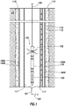
- Figure 1 illustrates a cross-sectional view a wellbore intersecting a subterranean formation.
- Casing 115 is cemented in borehole 112 through subterranean formation 105.
- Production tubing 117 is nested within casing 115.
- one or more conduits need to be perforated to allow communication of formation fluids into production tubing 117 to allow hydrocarbons to be produced to surface 110.
- both production tubing 117 and casing 115 need to be perforated to allow formation fluids into production tubing 117.
- production tubing terminates at some point above the interval to be produced.
- only casing 115 would need to be perforated as the terminal open end of production tubing 117 would permit flow into production tubing 117 without perforating production tubing 117.
- Senstyrene-based Perforation operations downhole must take into account the presence of any sensitive devices downhole in proximity to the conduits to avoid damaging the sensitive devices.
- the term "sensitive apparatus or device,” as used herein, refers to any downhole component to which it is desired to avoid damage.
- sensitive device 140A is attached to casing 115
- sensitive device 140B in this case, a cable, is attached to production tubing 117 opposite to sensitive device 140B. It is recognized that the sensitive devices may be situated anywhere in the near wellbore region, including, but not limited to, being attached to casing 115 or production tubing 117.
- the axis parallel to the conduits is referred to herein as a "longitudinal axis.”
- the term "radial axis,” as used herein, refers to the axis normal to the longitudinal axis and normal to the surface of the conduits. Stated another way, the radial axis is parallel to any plane that is normal to the longitudinal axis. Recognizing that over long distances, the direction of the conduits may change as a function of depth in subterranean formation 105, the terms longitudinal axis and radial axis refer to the orientation of the axis local to the region of interest. In Figure 1 , the longitudinal axis is labeled the "z" axis, whereas the radial axis is labeled the "x" axis.
- Radial orientation detection device 130 is run down through borehole 112 to determine the radial orientation of one or more downhole components, in this case, sensitive device 140A, sensitive device 140B, or both. Radial orientation detection device 130 works in conjunction with one or more target masses, in this case, target mass 150A, target mass 150B, or both. As will be explained in more detail, radial orientation detection device 130 is adapted to determine the radial orientation of a target mass.
- the radial orientation of the sensitive apparatus can be determined once the radial orientation of the target mass is determined. In this way, by determining the radial orientation of one of the target masses, the radial orientation of any corresponding sensitive apparatus may be deduced.
- a target mass may be situated directly adjacent to a sensitive device. As shown in Figure 1 , target mass 150A is situated directly adjacent to sensitive device 140A. Target mass 150B is situated in the same radial orientation as sensitive device 140B. In certain embodiments, the target mass may be integral to the sensitive device. In some embodiments, it may be preferred to clamp the target mass to the sensitive device. It is also recognized that a target mass may be located in any spatial relationship to its corresponding sensitive device by any radial offset angle.
- Figure 2 shows an aerial cross-section view, illustrating these concepts.
- Production tubing 117 is nested within casing 115.
- Sensitive devices 140A and 140C are attached to casing 115, and sensitive device 140B is attached to production tubing 117.
- Target masses 150A and 150B are also attached to casing 115.
- the term, "radial offset angle,” as used herein, refers to the radial angle between a target mass and its corresponding sensitive device. By knowing the radial offset angle between a target mass and a sensitive device, the radial orientation of the sensitive device may be deduced once the radial orientation of the corresponding target mass is determined.
- target mass 150A is situated at a radial offset angle ( ⁇ ) of about 110° from sensitive device 140C.
- Target mass 150A is situated at a radial offset angle of about 180° from sensitive device 140B, whereas target mass 150B is situated at a radial offset angle of about 180° from sensitive device 140A.
- a target mass may be situated at any radial spatial relationship relative to its corresponding sensitive device, that is, any angle between 0° and 360°.
- a perforation target may be determined.
- the perforation target refers to any radial orientation away from the sensitive device that, when perforated, avoids damage to the sensitive device.
- the perforation target may be a single radial orientation or a range of safe perforation angles, as desired.
- a perforation target will be chosen that is situated about 180° from the sensitive device to minimize damage to the sensitive device. Examples of suitable perforation targets include, but are not limited to, angles of about 170° to about 190° from the sensitive device.
- the target mass is located at the preferred perforation target or in the same radial orientation as the preferred perforation target.
- Radial orientation detection device 130 determines the radial orientation of a target mass.
- radial orientation detection device 130 comprises irradiation module 132 and radiation detection module 134.
- Target masses 150A and 150B are substantially nonradioactive so as to not pose a safety, health, or environmental threat when being handled above surface. The nonradioactivity of target masses 140A and 140B significantly eases the permitting, logistics, and handling of target masses 140A and 140B.
- the radial orientation of one of the target masses may be deduced since the radial offset angles between the target mass 150A and the sensitive devices 140A and 140B are known.
- the radial offset angle between 150A and 140A is about 10°
- the radial offset angle between 150A and 140B is about 180°. In this way, the radial orientation of either sensitive device 140A or 140B may be determined.
- a perforation target may be selected in a direction oriented substantially away from the sensitive devices.
- the perforation target is an angle or zone of angles about 180° from the sensitive device or from about 170° to about 190° from the sensitive device.
- the perforation target is chosen as any radial orientation that avoids or minimizes substantial risk of damage to the sensitive device.
- the perforation target is chosen as any radial orientation that acts as a guide for directing a perforation toward the target.
- irradiation module 132 radiation detection module 134, and perforation gun 136 are shown in Figure 1 as combined into one integral device, it is recognized that one or more of these modules may be formed into separate, stand-alone devices and may be configured in any order to make an assembly.
- the target mass comprises a material that is substantially radioactively inert.
- suitable target mass materials include, but are not limited to, boron, boronated compounds, gadolinium, cadmium, salts of any of the foregoing, or any combination thereof.
- radiation detection module 134 may detect the target mass as any area or region of reduced radioactive response. Normally, most materials become radioactive upon neutron irradiation or bombardment. Boron and boronated compounds, on the other hand, are unusual compared to most other materials in that they are substantially radioactively inert.
- substantially non-radioactive target masses may be located and their radial orientation determined. Accordingly, the radial orientation of any sensitive devices with known spatial relationships to the target mass may then be deduced. Again, by using substantially radioactively inert target masses, the safety, health, and environmental exposure risks associated with radioactive target masses may be avoided.
Landscapes
- Life Sciences & Earth Sciences (AREA)
- Geology (AREA)
- Engineering & Computer Science (AREA)
- Mining & Mineral Resources (AREA)
- Physics & Mathematics (AREA)
- General Life Sciences & Earth Sciences (AREA)
- Environmental & Geological Engineering (AREA)
- Fluid Mechanics (AREA)
- Geochemistry & Mineralogy (AREA)
- Geophysics (AREA)
- Geophysics And Detection Of Objects (AREA)
- High Energy & Nuclear Physics (AREA)
- General Physics & Mathematics (AREA)
- Particle Accelerators (AREA)
Claims (9)
- Procédé de perforation d'une conduite (115, 117) disposée dans une formation souterraine, comprenant les étapes consistant à :fournir une masse cible (150A, 150B), dans lequel la masse cible est sensiblement inerte au plan radioactif;dans lequel la conduite est caractérisée par un axe longitudinal et un axe radial ;localiser la masse cible (150A, 150B) à proximité de la conduite (115, 117), dans lequel la masse cible est située sous un angle radial décalé d'un appareil sensible (140A, 140B) ;irradier une région autour de la masse cible (150A, 150B) ;détecter l'emplacement radial de la masse cible (150A, 150B) comme une zone de réponse radioactive réduite ;déterminer une cible de perforation sur la base de l'emplacement radial de la masse cible (150A, 150B) et de l'angle radial décalé de manière à réduire le risque d'un dommage à l'appareil sensible (140A, 140B) ; etperforer la conduite (115, 117) au niveau de la cible de perforation dans une direction qui s'écarte sensiblement de l'appareil sensible (140A, 140B) de manière à ne pas endommager l'appareil sensible.
- Procédé selon la revendication 1, dans lequel la masse cible (150A, 150B) est formée de bore, d'un composé boré, de gadolinium, de cadmium, de sels de l'un quelconque des corps précédents ou d'une de leurs combinaisons.
- Procédé selon la revendication 1, dans lequel la masse cible (150A, 150B) est située de manière directement adjacente à l'appareil sensible.
- Procédé selon la revendication 1, dans lequel l'appareil sensible (140A, 140B) est un câble.
- Procédé selon la revendication 1, comprenant en outre l'étape de fixation de l'appareil sensible (140A, 140B) à la conduite et dans lequel l'étape de localisation de la masse cible (150A, 150B) comprend en outre l'assemblage de la masse cible (150A, 150B) à l'appareil sensible (140A, 140B).
- Procédé selon la revendication 1, dans lequel l'étape de détection de l'emplacement radial de la masse cible comprend en outre l'étape de détection de l'emplacement radial de la masse cible (150A, 150B) en utilisant un détecteur de rayons gamma.
- Procédé selon la revendication 1, dans lequel l'angle radial décalé est d'environ 0° ou d'environ 180°.
- Procédé selon la revendication 1, dans lequel la cible de perforation est située radialement aux environs de 180° de l'appareil sensible (140A, 140B).
- Procédé selon la revendication 1, dans lequel la cible de perforation est située radialement à environ 170° à environ 190° de l'appareil sensible (140A, 140B).
Applications Claiming Priority (4)
| Application Number | Priority Date | Filing Date | Title |
|---|---|---|---|
| US201161505739P | 2011-07-08 | 2011-07-08 | |
| US201161505725P | 2011-07-08 | 2011-07-08 | |
| PCT/US2012/045244 WO2013009515A1 (fr) | 2011-07-08 | 2012-07-02 | Outil de détection de profondeur / d'orientation et procédés associés |
| US13/539,641 US20130008646A1 (en) | 2011-07-08 | 2012-07-02 | Depth/orientation detection tool and methods thereof |
Publications (3)
| Publication Number | Publication Date |
|---|---|
| EP2729663A1 EP2729663A1 (fr) | 2014-05-14 |
| EP2729663A4 EP2729663A4 (fr) | 2016-06-01 |
| EP2729663B1 true EP2729663B1 (fr) | 2017-12-27 |
Family
ID=47437944
Family Applications (2)
| Application Number | Title | Priority Date | Filing Date |
|---|---|---|---|
| EP12810701.8A Active EP2729663B1 (fr) | 2011-07-08 | 2012-07-02 | Procédé de perforation d'une conduite disposée dans une formation souterraine |
| EP12810626.7A Withdrawn EP2729660A4 (fr) | 2011-07-08 | 2012-07-02 | Outil électromagnétique de détection de profondeur et d'orientation et procédés associés |
Family Applications After (1)
| Application Number | Title | Priority Date | Filing Date |
|---|---|---|---|
| EP12810626.7A Withdrawn EP2729660A4 (fr) | 2011-07-08 | 2012-07-02 | Outil électromagnétique de détection de profondeur et d'orientation et procédés associés |
Country Status (7)
| Country | Link |
|---|---|
| US (2) | US20130008650A1 (fr) |
| EP (2) | EP2729663B1 (fr) |
| CN (3) | CN103703214A (fr) |
| AU (2) | AU2012283033B2 (fr) |
| BR (2) | BR112014000449A2 (fr) |
| CA (1) | CA2838957C (fr) |
| WO (2) | WO2013009513A1 (fr) |
Families Citing this family (8)
| Publication number | Priority date | Publication date | Assignee | Title |
|---|---|---|---|---|
| KR101468917B1 (ko) * | 2013-01-24 | 2014-12-04 | 서울대학교병원 (분사무소) | 전자의무기록 시스템 기반 데이터 표시 방법 및 장치 |
| MX367501B (es) * | 2013-02-20 | 2019-07-15 | Roke Tech Ltd | Dispositivo y sistema para la medicion de neutrones de fuentes multiples y uso de los mismos. |
| EP2966258B1 (fr) | 2014-07-10 | 2018-11-21 | Services Petroliers Schlumberger | Positionnement de profondeur au moyen de corrélation de rayon gamma et différentiel de paramètres de fond de trou |
| US20170058662A1 (en) * | 2015-08-31 | 2017-03-02 | Curtis G. Blount | Locating pipe external equipment in a wellbore |
| EP3181810B1 (fr) * | 2015-12-18 | 2022-03-23 | Services Pétroliers Schlumberger | Distribution d'étiquettes radioactives autour ou le long d'un puits pour la détection de celui-ci |
| US10323505B2 (en) | 2016-01-12 | 2019-06-18 | Halliburton Energy Services, Inc. | Radioactive tag detection for downhole positioning |
| CN109653730B (zh) * | 2018-12-12 | 2021-12-14 | 中法渤海地质服务有限公司 | 一种用于钻杆地层测试作业井下射孔井段深度校准方法 |
| CN110094197B (zh) * | 2019-05-13 | 2022-04-22 | 重庆科技学院 | 预防水平井管柱光缆射孔损伤的方法 |
Family Cites Families (48)
| Publication number | Priority date | Publication date | Assignee | Title |
|---|---|---|---|---|
| US2728554A (en) * | 1952-08-04 | 1955-12-27 | Eastman Oil Well Survey Co | Means for orienting tools in well bores |
| US3180409A (en) * | 1959-09-29 | 1965-04-27 | Schlumberger Well Surv Corp | Orienting systems |
| US3175608A (en) * | 1960-10-21 | 1965-03-30 | Dresser Ind | Method and apparatus for directional tubing perforation |
| US3291207A (en) * | 1960-12-19 | 1966-12-13 | Exxon Production Research Co | Well completion method |
| US3209828A (en) * | 1962-11-01 | 1965-10-05 | Schlumberger Well Surv Corp | Perforating apparatus |
| US3342275A (en) * | 1963-09-05 | 1967-09-19 | Dresser Ind | Apparatus for directional tubing perforation |
| FR2192320B1 (fr) * | 1972-07-13 | 1975-03-07 | Schlumberger Prospection | |
| US4233508A (en) | 1978-12-18 | 1980-11-11 | Texaco Inc. | Water injection profiling |
| CA1184877A (fr) | 1982-05-12 | 1985-04-02 | James B. Webb | Methode et dispositif pour deposer un oxyde conducteur sur un substrat |
| US4700142A (en) | 1986-04-04 | 1987-10-13 | Vector Magnetics, Inc. | Method for determining the location of a deep-well casing by magnetic field sensing |
| FR2636436B1 (fr) * | 1988-09-14 | 1990-11-30 | Schlumberger Prospection | Procede et dispositif de mesure de subsidence |
| WO1995019489A1 (fr) * | 1992-09-01 | 1995-07-20 | Scholes Patrick L | Procede de commande de travail au cable dans des puits de forage a anneau de cuvelage |
| US5279366A (en) * | 1992-09-01 | 1994-01-18 | Scholes Patrick L | Method for wireline operation depth control in cased wells |
| US5351755A (en) | 1993-08-02 | 1994-10-04 | Texaco Inc. | Method and apparatus for establish the orientation of tools in a cased borehole |
| US5548116A (en) * | 1994-03-01 | 1996-08-20 | Optoscint, Inc. | Long life oil well logging assembly |
| US5705812A (en) * | 1996-05-31 | 1998-01-06 | Western Atlas International, Inc. | Compaction monitoring instrument system |
| US5753813A (en) * | 1996-07-19 | 1998-05-19 | Halliburton Energy Services, Inc. | Apparatus and method for monitoring formation compaction with improved accuracy |
| CN2339747Y (zh) * | 1997-12-26 | 1999-09-22 | 廊坊开发区中油金达测井试井技术有限公司 | 油气井跨隔射孔一测试联作施工管柱装置 |
| CN2321939Y (zh) * | 1998-01-26 | 1999-06-02 | 四川石油管理局测井公司 | 石油开采射孔方位石英式定向装置 |
| US6386288B1 (en) * | 1999-04-27 | 2002-05-14 | Marathon Oil Company | Casing conveyed perforating process and apparatus |
| US6378607B1 (en) * | 1999-06-09 | 2002-04-30 | Schlumberger Technology Corporation | Method and system for oriented perforating in a well with permanent sensors |
| US6318463B1 (en) * | 1999-09-24 | 2001-11-20 | Halliburton Energy Services, Inc. | Slickline fluid indentification tool and method of use |
| US6614229B1 (en) | 2000-03-27 | 2003-09-02 | Schlumberger Technology Corporation | System and method for monitoring a reservoir and placing a borehole using a modified tubular |
| GB2374887B (en) * | 2001-04-27 | 2003-12-17 | Schlumberger Holdings | Method and apparatus for orienting perforating devices |
| US6725927B2 (en) * | 2002-02-25 | 2004-04-27 | Schlumberger Technology Corporation | Method and system for avoiding damage to behind-casing structures |
| WO2003083248A2 (fr) * | 2002-03-27 | 2003-10-09 | Union Oil Company Of California | Procede et appareil de perforation |
| US20060048937A1 (en) * | 2004-09-09 | 2006-03-09 | Pinto C J | Perforation method and apparatus |
| US6843318B2 (en) * | 2003-04-10 | 2005-01-18 | Halliburton Energy Services, Inc. | Method and system for determining the position and orientation of a device in a well casing |
| US6847207B1 (en) * | 2004-04-15 | 2005-01-25 | Tdw Delaware, Inc. | ID-OD discrimination sensor concept for a magnetic flux leakage inspection tool |
| US7136765B2 (en) * | 2005-02-09 | 2006-11-14 | Deepsea Power & Light, Inc. | Buried object locating and tracing method and system employing principal components analysis for blind signal detection |
| CN1712668A (zh) * | 2005-07-13 | 2005-12-28 | 吉林大学 | 油井套管射孔孔眼质量的磁检测装置 |
| US7231017B2 (en) * | 2005-07-27 | 2007-06-12 | Physical Optics Corporation | Lobster eye X-ray imaging system and method of fabrication thereof |
| US7726397B2 (en) * | 2005-08-09 | 2010-06-01 | Hexion Specialty Chemicals, Inc. | Methods and compositions for determination of fracture geometry in subterranean formations |
| US7383883B2 (en) * | 2005-08-15 | 2008-06-10 | Schlumberger Technology Corporation | Apparatus and method to detect a signal associated with a component |
| US7591307B2 (en) | 2006-09-07 | 2009-09-22 | Sondex Ltd | Method of and system for determining the free point in a drill pipe |
| US8122954B2 (en) | 2006-09-20 | 2012-02-28 | Baker Hughes Incorporated | Downhole depth computation methods and related system |
| US20090087912A1 (en) * | 2007-09-28 | 2009-04-02 | Shlumberger Technology Corporation | Tagged particles for downhole application |
| US8201625B2 (en) * | 2007-12-26 | 2012-06-19 | Schlumberger Technology Corporation | Borehole imaging and orientation of downhole tools |
| US9607720B2 (en) * | 2008-02-27 | 2017-03-28 | Starfire Industries Llc | Long life high efficiency neutron generator |
| US8020619B1 (en) * | 2008-03-26 | 2011-09-20 | Robertson Intellectual Properties, LLC | Severing of downhole tubing with associated cable |
| US8191416B2 (en) * | 2008-11-24 | 2012-06-05 | Schlumberger Technology Corporation | Instrumented formation tester for injecting and monitoring of fluids |
| US8573297B2 (en) * | 2010-03-09 | 2013-11-05 | Conocophillips Company | Subterranean formation deformation monitoring systems |
| CN201786342U (zh) * | 2010-04-29 | 2011-04-06 | 中国石油化工集团公司 | 高精度定方位射孔器 |
| CN201696012U (zh) * | 2010-06-09 | 2011-01-05 | 中国石油集团川庆钻探工程有限公司 | 由壬式外定方位射孔器 |
| CN101892833A (zh) * | 2010-07-02 | 2010-11-24 | 大庆油田有限责任公司 | 一种油水井用垂直井壁小孔径裸眼水平井钻井的压力监测方法 |
| US8669516B2 (en) * | 2010-08-20 | 2014-03-11 | Baker Hughes Incorporated | Using LWT service to identify loss circulation areas in a wellbore |
| US9116016B2 (en) * | 2011-06-30 | 2015-08-25 | Schlumberger Technology Corporation | Indicating system for a downhole apparatus and a method for locating a downhole apparatus |
| US8893785B2 (en) * | 2012-06-12 | 2014-11-25 | Halliburton Energy Services, Inc. | Location of downhole lines |
-
2012
- 2012-07-02 CA CA2838957A patent/CA2838957C/fr active Active
- 2012-07-02 CN CN201280033927.4A patent/CN103703214A/zh active Pending
- 2012-07-02 CN CN201710156548.9A patent/CN107023286B/zh active Active
- 2012-07-02 AU AU2012283033A patent/AU2012283033B2/en active Active
- 2012-07-02 EP EP12810701.8A patent/EP2729663B1/fr active Active
- 2012-07-02 BR BR112014000449A patent/BR112014000449A2/pt not_active IP Right Cessation
- 2012-07-02 WO PCT/US2012/045232 patent/WO2013009513A1/fr not_active Ceased
- 2012-07-02 US US13/539,597 patent/US20130008650A1/en not_active Abandoned
- 2012-07-02 EP EP12810626.7A patent/EP2729660A4/fr not_active Withdrawn
- 2012-07-02 WO PCT/US2012/045244 patent/WO2013009515A1/fr not_active Ceased
- 2012-07-02 AU AU2012283031A patent/AU2012283031A1/en not_active Abandoned
- 2012-07-02 CN CN201280031617.9A patent/CN103620160A/zh active Pending
- 2012-07-02 BR BR112014000328A patent/BR112014000328B8/pt active IP Right Grant
-
2016
- 2016-08-30 US US15/251,057 patent/US10526887B2/en active Active
Non-Patent Citations (1)
| Title |
|---|
| None * |
Also Published As
| Publication number | Publication date |
|---|---|
| BR112014000328B8 (pt) | 2021-08-03 |
| WO2013009513A1 (fr) | 2013-01-17 |
| CN103620160A (zh) | 2014-03-05 |
| CN103703214A (zh) | 2014-04-02 |
| CA2838957C (fr) | 2019-05-21 |
| US20130008650A1 (en) | 2013-01-10 |
| BR112014000449A2 (pt) | 2017-02-14 |
| CA2838957A1 (fr) | 2013-01-17 |
| WO2013009515A1 (fr) | 2013-01-17 |
| EP2729660A4 (fr) | 2016-06-01 |
| CN107023286A (zh) | 2017-08-08 |
| EP2729660A1 (fr) | 2014-05-14 |
| BR112014000328B1 (pt) | 2021-01-05 |
| CN107023286B (zh) | 2021-04-06 |
| EP2729663A4 (fr) | 2016-06-01 |
| US20170002647A1 (en) | 2017-01-05 |
| AU2012283033A1 (en) | 2014-01-16 |
| AU2012283031A1 (en) | 2013-12-19 |
| US10526887B2 (en) | 2020-01-07 |
| AU2012283033B2 (en) | 2017-03-23 |
| EP2729663A1 (fr) | 2014-05-14 |
| BR112014000328A2 (pt) | 2017-02-07 |
Similar Documents
| Publication | Publication Date | Title |
|---|---|---|
| EP2729663B1 (fr) | Procédé de perforation d'une conduite disposée dans une formation souterraine | |
| US20130008646A1 (en) | Depth/orientation detection tool and methods thereof | |
| EP3250781B1 (fr) | Appareil de coupe et d'obturation de fond de trou | |
| US10273787B2 (en) | Creating radial slots in a wellbore | |
| EP3277916B1 (fr) | Bouchage et abandon puits de forage | |
| US10221667B2 (en) | Laser cutting with convex deflector | |
| US8028751B2 (en) | Perforation method and apparatus | |
| US11077521B2 (en) | Creating radial slots in a subterranean formation | |
| WO2017172289A1 (fr) | Procédé de détermination de l'état et de la position d'éléments dans un système de complétion | |
| SA520420480B1 (ar) | مفهوم تثقيب مُركب خارجيًا ويتم عبر التغليف | |
| US20070034374A1 (en) | Apparatus and Method To Detect A Signal Associated With A Component | |
| EP4141216B1 (fr) | Procédé pour télémétrie et détection de proximité pour puits de forage | |
| WO2003083248A2 (fr) | Procede et appareil de perforation | |
| Wood et al. | Perforating vertical smart well completions using tubing-conveyed perforating gun assemblies: case history |
Legal Events
| Date | Code | Title | Description |
|---|---|---|---|
| PUAI | Public reference made under article 153(3) epc to a published international application that has entered the european phase |
Free format text: ORIGINAL CODE: 0009012 |
|
| 17P | Request for examination filed |
Effective date: 20131211 |
|
| AK | Designated contracting states |
Kind code of ref document: A1 Designated state(s): AL AT BE BG CH CY CZ DE DK EE ES FI FR GB GR HR HU IE IS IT LI LT LU LV MC MK MT NL NO PL PT RO RS SE SI SK SM TR |
|
| DAX | Request for extension of the european patent (deleted) | ||
| RIC1 | Information provided on ipc code assigned before grant |
Ipc: E21B 43/119 20060101AFI20151123BHEP |
|
| REG | Reference to a national code |
Ref country code: DE Ref legal event code: R079 Ref document number: 602012041433 Country of ref document: DE Free format text: PREVIOUS MAIN CLASS: E21B0047024000 Ipc: E21B0043119000 |
|
| RA4 | Supplementary search report drawn up and despatched (corrected) |
Effective date: 20160503 |
|
| RIC1 | Information provided on ipc code assigned before grant |
Ipc: E21B 43/119 20060101AFI20160426BHEP |
|
| 17Q | First examination report despatched |
Effective date: 20160613 |
|
| STAA | Information on the status of an ep patent application or granted ep patent |
Free format text: STATUS: EXAMINATION IS IN PROGRESS |
|
| GRAP | Despatch of communication of intention to grant a patent |
Free format text: ORIGINAL CODE: EPIDOSNIGR1 |
|
| STAA | Information on the status of an ep patent application or granted ep patent |
Free format text: STATUS: GRANT OF PATENT IS INTENDED |
|
| INTG | Intention to grant announced |
Effective date: 20170726 |
|
| GRAS | Grant fee paid |
Free format text: ORIGINAL CODE: EPIDOSNIGR3 |
|
| GRAA | (expected) grant |
Free format text: ORIGINAL CODE: 0009210 |
|
| STAA | Information on the status of an ep patent application or granted ep patent |
Free format text: STATUS: THE PATENT HAS BEEN GRANTED |
|
| AK | Designated contracting states |
Kind code of ref document: B1 Designated state(s): AL AT BE BG CH CY CZ DE DK EE ES FI FR GB GR HR HU IE IS IT LI LT LU LV MC MK MT NL NO PL PT RO RS SE SI SK SM TR |
|
| REG | Reference to a national code |
Ref country code: GB Ref legal event code: FG4D |
|
| REG | Reference to a national code |
Ref country code: CH Ref legal event code: EP |
|
| REG | Reference to a national code |
Ref country code: AT Ref legal event code: REF Ref document number: 958474 Country of ref document: AT Kind code of ref document: T Effective date: 20180115 |
|
| REG | Reference to a national code |
Ref country code: IE Ref legal event code: FG4D |
|
| REG | Reference to a national code |
Ref country code: DE Ref legal event code: R096 Ref document number: 602012041433 Country of ref document: DE |
|
| REG | Reference to a national code |
Ref country code: NO Ref legal event code: T2 Effective date: 20171227 |
|
| PG25 | Lapsed in a contracting state [announced via postgrant information from national office to epo] |
Ref country code: LT Free format text: LAPSE BECAUSE OF FAILURE TO SUBMIT A TRANSLATION OF THE DESCRIPTION OR TO PAY THE FEE WITHIN THE PRESCRIBED TIME-LIMIT Effective date: 20171227 Ref country code: FI Free format text: LAPSE BECAUSE OF FAILURE TO SUBMIT A TRANSLATION OF THE DESCRIPTION OR TO PAY THE FEE WITHIN THE PRESCRIBED TIME-LIMIT Effective date: 20171227 |
|
| REG | Reference to a national code |
Ref country code: NL Ref legal event code: MP Effective date: 20171227 |
|
| REG | Reference to a national code |
Ref country code: LT Ref legal event code: MG4D |
|
| REG | Reference to a national code |
Ref country code: AT Ref legal event code: MK05 Ref document number: 958474 Country of ref document: AT Kind code of ref document: T Effective date: 20171227 |
|
| PG25 | Lapsed in a contracting state [announced via postgrant information from national office to epo] |
Ref country code: RS Free format text: LAPSE BECAUSE OF FAILURE TO SUBMIT A TRANSLATION OF THE DESCRIPTION OR TO PAY THE FEE WITHIN THE PRESCRIBED TIME-LIMIT Effective date: 20171227 Ref country code: HR Free format text: LAPSE BECAUSE OF FAILURE TO SUBMIT A TRANSLATION OF THE DESCRIPTION OR TO PAY THE FEE WITHIN THE PRESCRIBED TIME-LIMIT Effective date: 20171227 Ref country code: BG Free format text: LAPSE BECAUSE OF FAILURE TO SUBMIT A TRANSLATION OF THE DESCRIPTION OR TO PAY THE FEE WITHIN THE PRESCRIBED TIME-LIMIT Effective date: 20180327 Ref country code: GR Free format text: LAPSE BECAUSE OF FAILURE TO SUBMIT A TRANSLATION OF THE DESCRIPTION OR TO PAY THE FEE WITHIN THE PRESCRIBED TIME-LIMIT Effective date: 20180328 Ref country code: LV Free format text: LAPSE BECAUSE OF FAILURE TO SUBMIT A TRANSLATION OF THE DESCRIPTION OR TO PAY THE FEE WITHIN THE PRESCRIBED TIME-LIMIT Effective date: 20171227 |
|
| PG25 | Lapsed in a contracting state [announced via postgrant information from national office to epo] |
Ref country code: NL Free format text: LAPSE BECAUSE OF FAILURE TO SUBMIT A TRANSLATION OF THE DESCRIPTION OR TO PAY THE FEE WITHIN THE PRESCRIBED TIME-LIMIT Effective date: 20171227 |
|
| PG25 | Lapsed in a contracting state [announced via postgrant information from national office to epo] |
Ref country code: EE Free format text: LAPSE BECAUSE OF FAILURE TO SUBMIT A TRANSLATION OF THE DESCRIPTION OR TO PAY THE FEE WITHIN THE PRESCRIBED TIME-LIMIT Effective date: 20171227 Ref country code: SK Free format text: LAPSE BECAUSE OF FAILURE TO SUBMIT A TRANSLATION OF THE DESCRIPTION OR TO PAY THE FEE WITHIN THE PRESCRIBED TIME-LIMIT Effective date: 20171227 Ref country code: CY Free format text: LAPSE BECAUSE OF FAILURE TO SUBMIT A TRANSLATION OF THE DESCRIPTION OR TO PAY THE FEE WITHIN THE PRESCRIBED TIME-LIMIT Effective date: 20171227 Ref country code: CZ Free format text: LAPSE BECAUSE OF FAILURE TO SUBMIT A TRANSLATION OF THE DESCRIPTION OR TO PAY THE FEE WITHIN THE PRESCRIBED TIME-LIMIT Effective date: 20171227 Ref country code: ES Free format text: LAPSE BECAUSE OF FAILURE TO SUBMIT A TRANSLATION OF THE DESCRIPTION OR TO PAY THE FEE WITHIN THE PRESCRIBED TIME-LIMIT Effective date: 20171227 |
|
| PG25 | Lapsed in a contracting state [announced via postgrant information from national office to epo] |
Ref country code: SM Free format text: LAPSE BECAUSE OF FAILURE TO SUBMIT A TRANSLATION OF THE DESCRIPTION OR TO PAY THE FEE WITHIN THE PRESCRIBED TIME-LIMIT Effective date: 20171227 Ref country code: PL Free format text: LAPSE BECAUSE OF FAILURE TO SUBMIT A TRANSLATION OF THE DESCRIPTION OR TO PAY THE FEE WITHIN THE PRESCRIBED TIME-LIMIT Effective date: 20171227 Ref country code: IS Free format text: LAPSE BECAUSE OF FAILURE TO SUBMIT A TRANSLATION OF THE DESCRIPTION OR TO PAY THE FEE WITHIN THE PRESCRIBED TIME-LIMIT Effective date: 20180427 Ref country code: RO Free format text: LAPSE BECAUSE OF FAILURE TO SUBMIT A TRANSLATION OF THE DESCRIPTION OR TO PAY THE FEE WITHIN THE PRESCRIBED TIME-LIMIT Effective date: 20171227 Ref country code: IT Free format text: LAPSE BECAUSE OF FAILURE TO SUBMIT A TRANSLATION OF THE DESCRIPTION OR TO PAY THE FEE WITHIN THE PRESCRIBED TIME-LIMIT Effective date: 20171227 Ref country code: AT Free format text: LAPSE BECAUSE OF FAILURE TO SUBMIT A TRANSLATION OF THE DESCRIPTION OR TO PAY THE FEE WITHIN THE PRESCRIBED TIME-LIMIT Effective date: 20171227 |
|
| REG | Reference to a national code |
Ref country code: DE Ref legal event code: R097 Ref document number: 602012041433 Country of ref document: DE |
|
| PLBE | No opposition filed within time limit |
Free format text: ORIGINAL CODE: 0009261 |
|
| STAA | Information on the status of an ep patent application or granted ep patent |
Free format text: STATUS: NO OPPOSITION FILED WITHIN TIME LIMIT |
|
| PG25 | Lapsed in a contracting state [announced via postgrant information from national office to epo] |
Ref country code: DK Free format text: LAPSE BECAUSE OF FAILURE TO SUBMIT A TRANSLATION OF THE DESCRIPTION OR TO PAY THE FEE WITHIN THE PRESCRIBED TIME-LIMIT Effective date: 20171227 |
|
| 26N | No opposition filed |
Effective date: 20180928 |
|
| REG | Reference to a national code |
Ref country code: DE Ref legal event code: R119 Ref document number: 602012041433 Country of ref document: DE |
|
| PG25 | Lapsed in a contracting state [announced via postgrant information from national office to epo] |
Ref country code: SI Free format text: LAPSE BECAUSE OF FAILURE TO SUBMIT A TRANSLATION OF THE DESCRIPTION OR TO PAY THE FEE WITHIN THE PRESCRIBED TIME-LIMIT Effective date: 20171227 |
|
| REG | Reference to a national code |
Ref country code: CH Ref legal event code: PL |
|
| PG25 | Lapsed in a contracting state [announced via postgrant information from national office to epo] |
Ref country code: MC Free format text: LAPSE BECAUSE OF FAILURE TO SUBMIT A TRANSLATION OF THE DESCRIPTION OR TO PAY THE FEE WITHIN THE PRESCRIBED TIME-LIMIT Effective date: 20171227 Ref country code: LU Free format text: LAPSE BECAUSE OF NON-PAYMENT OF DUE FEES Effective date: 20180702 |
|
| REG | Reference to a national code |
Ref country code: BE Ref legal event code: MM Effective date: 20180731 |
|
| REG | Reference to a national code |
Ref country code: IE Ref legal event code: MM4A |
|
| PG25 | Lapsed in a contracting state [announced via postgrant information from national office to epo] |
Ref country code: LI Free format text: LAPSE BECAUSE OF NON-PAYMENT OF DUE FEES Effective date: 20180731 Ref country code: CH Free format text: LAPSE BECAUSE OF NON-PAYMENT OF DUE FEES Effective date: 20180731 Ref country code: DE Free format text: LAPSE BECAUSE OF NON-PAYMENT OF DUE FEES Effective date: 20190201 Ref country code: IE Free format text: LAPSE BECAUSE OF NON-PAYMENT OF DUE FEES Effective date: 20180702 Ref country code: FR Free format text: LAPSE BECAUSE OF NON-PAYMENT OF DUE FEES Effective date: 20180731 |
|
| PG25 | Lapsed in a contracting state [announced via postgrant information from national office to epo] |
Ref country code: BE Free format text: LAPSE BECAUSE OF NON-PAYMENT OF DUE FEES Effective date: 20180731 |
|
| PG25 | Lapsed in a contracting state [announced via postgrant information from national office to epo] |
Ref country code: MT Free format text: LAPSE BECAUSE OF NON-PAYMENT OF DUE FEES Effective date: 20180702 |
|
| PG25 | Lapsed in a contracting state [announced via postgrant information from national office to epo] |
Ref country code: TR Free format text: LAPSE BECAUSE OF FAILURE TO SUBMIT A TRANSLATION OF THE DESCRIPTION OR TO PAY THE FEE WITHIN THE PRESCRIBED TIME-LIMIT Effective date: 20171227 |
|
| PG25 | Lapsed in a contracting state [announced via postgrant information from national office to epo] |
Ref country code: PT Free format text: LAPSE BECAUSE OF FAILURE TO SUBMIT A TRANSLATION OF THE DESCRIPTION OR TO PAY THE FEE WITHIN THE PRESCRIBED TIME-LIMIT Effective date: 20171227 Ref country code: HU Free format text: LAPSE BECAUSE OF FAILURE TO SUBMIT A TRANSLATION OF THE DESCRIPTION OR TO PAY THE FEE WITHIN THE PRESCRIBED TIME-LIMIT; INVALID AB INITIO Effective date: 20120702 |
|
| PG25 | Lapsed in a contracting state [announced via postgrant information from national office to epo] |
Ref country code: SE Free format text: LAPSE BECAUSE OF FAILURE TO SUBMIT A TRANSLATION OF THE DESCRIPTION OR TO PAY THE FEE WITHIN THE PRESCRIBED TIME-LIMIT Effective date: 20171227 Ref country code: MK Free format text: LAPSE BECAUSE OF NON-PAYMENT OF DUE FEES Effective date: 20171227 |
|
| PG25 | Lapsed in a contracting state [announced via postgrant information from national office to epo] |
Ref country code: AL Free format text: LAPSE BECAUSE OF FAILURE TO SUBMIT A TRANSLATION OF THE DESCRIPTION OR TO PAY THE FEE WITHIN THE PRESCRIBED TIME-LIMIT Effective date: 20171227 |
|
| P01 | Opt-out of the competence of the unified patent court (upc) registered |
Effective date: 20231207 |
|
| PGFP | Annual fee paid to national office [announced via postgrant information from national office to epo] |
Ref country code: GB Payment date: 20250619 Year of fee payment: 14 |
|
| PGFP | Annual fee paid to national office [announced via postgrant information from national office to epo] |
Ref country code: NO Payment date: 20250623 Year of fee payment: 14 |