EP2729708B1 - Collier de serrage en v comportant des segments d'insertion en v - Google Patents
Collier de serrage en v comportant des segments d'insertion en v Download PDFInfo
- Publication number
- EP2729708B1 EP2729708B1 EP12808092.6A EP12808092A EP2729708B1 EP 2729708 B1 EP2729708 B1 EP 2729708B1 EP 12808092 A EP12808092 A EP 12808092A EP 2729708 B1 EP2729708 B1 EP 2729708B1
- Authority
- EP
- European Patent Office
- Prior art keywords
- band
- insert
- segments
- latch assembly
- insert segments
- Prior art date
- Legal status (The legal status is an assumption and is not a legal conclusion. Google has not performed a legal analysis and makes no representation as to the accuracy of the status listed.)
- Not-in-force
Links
Images


Classifications
-
- F—MECHANICAL ENGINEERING; LIGHTING; HEATING; WEAPONS; BLASTING
- F16—ENGINEERING ELEMENTS AND UNITS; GENERAL MEASURES FOR PRODUCING AND MAINTAINING EFFECTIVE FUNCTIONING OF MACHINES OR INSTALLATIONS; THERMAL INSULATION IN GENERAL
- F16L—PIPES; JOINTS OR FITTINGS FOR PIPES; SUPPORTS FOR PIPES, CABLES OR PROTECTIVE TUBING; MEANS FOR THERMAL INSULATION IN GENERAL
- F16L37/00—Couplings of the quick-acting type
- F16L37/08—Couplings of the quick-acting type in which the connection between abutting or axially overlapping ends is maintained by locking members
- F16L37/12—Couplings of the quick-acting type in which the connection between abutting or axially overlapping ends is maintained by locking members using hooks, pawls, or other movable or insertable locking members
- F16L37/20—Joints tightened by toggle-action levers
-
- F—MECHANICAL ENGINEERING; LIGHTING; HEATING; WEAPONS; BLASTING
- F16—ENGINEERING ELEMENTS AND UNITS; GENERAL MEASURES FOR PRODUCING AND MAINTAINING EFFECTIVE FUNCTIONING OF MACHINES OR INSTALLATIONS; THERMAL INSULATION IN GENERAL
- F16L—PIPES; JOINTS OR FITTINGS FOR PIPES; SUPPORTS FOR PIPES, CABLES OR PROTECTIVE TUBING; MEANS FOR THERMAL INSULATION IN GENERAL
- F16L23/00—Flanged joints
- F16L23/04—Flanged joints the flanges being connected by members tensioned in the radial plane
- F16L23/08—Flanged joints the flanges being connected by members tensioned in the radial plane connection by tangentially arranged pin and nut
- F16L23/10—Flanged joints the flanges being connected by members tensioned in the radial plane connection by tangentially arranged pin and nut with a pivoting or swinging pin
-
- F—MECHANICAL ENGINEERING; LIGHTING; HEATING; WEAPONS; BLASTING
- F01—MACHINES OR ENGINES IN GENERAL; ENGINE PLANTS IN GENERAL; STEAM ENGINES
- F01N—GAS-FLOW SILENCERS OR EXHAUST APPARATUS FOR MACHINES OR ENGINES IN GENERAL; GAS-FLOW SILENCERS OR EXHAUST APPARATUS FOR INTERNAL-COMBUSTION ENGINES
- F01N13/00—Exhaust or silencing apparatus characterised by constructional features
- F01N13/18—Construction facilitating manufacture, assembly, or disassembly
- F01N13/1838—Construction facilitating manufacture, assembly, or disassembly characterised by the type of connection between parts of exhaust or silencing apparatus, e.g. between housing and tubes, between tubes and baffles
-
- F—MECHANICAL ENGINEERING; LIGHTING; HEATING; WEAPONS; BLASTING
- F16—ENGINEERING ELEMENTS AND UNITS; GENERAL MEASURES FOR PRODUCING AND MAINTAINING EFFECTIVE FUNCTIONING OF MACHINES OR INSTALLATIONS; THERMAL INSULATION IN GENERAL
- F16B—DEVICES FOR FASTENING OR SECURING CONSTRUCTIONAL ELEMENTS OR MACHINE PARTS TOGETHER, e.g. NAILS, BOLTS, CIRCLIPS, CLAMPS, CLIPS OR WEDGES; JOINTS OR JOINTING
- F16B2/00—Friction-grip releasable fastenings
- F16B2/02—Clamps, i.e. with gripping action effected by positive means other than the inherent resistance to deformation of the material of the fastening
- F16B2/06—Clamps, i.e. with gripping action effected by positive means other than the inherent resistance to deformation of the material of the fastening external, i.e. with contracting action
- F16B2/08—Clamps, i.e. with gripping action effected by positive means other than the inherent resistance to deformation of the material of the fastening external, i.e. with contracting action using bands
-
- Y—GENERAL TAGGING OF NEW TECHNOLOGICAL DEVELOPMENTS; GENERAL TAGGING OF CROSS-SECTIONAL TECHNOLOGIES SPANNING OVER SEVERAL SECTIONS OF THE IPC; TECHNICAL SUBJECTS COVERED BY FORMER USPC CROSS-REFERENCE ART COLLECTIONS [XRACs] AND DIGESTS
- Y10—TECHNICAL SUBJECTS COVERED BY FORMER USPC
- Y10T—TECHNICAL SUBJECTS COVERED BY FORMER US CLASSIFICATION
- Y10T24/00—Buckles, buttons, clasps, etc.
- Y10T24/14—Bale and package ties, hose clamps
- Y10T24/1412—Bale and package ties, hose clamps with tighteners
- Y10T24/1424—Lever
Definitions
- This invention relates to v-band clamps for joining tubular bodies, and to v-band clamps having v-insert segments.
- V-band clamps are typically used to join tubular bodies that have end flanges extending outwardly from the main tubular structures of the tubular bodies. These types of tubular bodies are used in automotive exhaust systems and in other applications.
- V-band clamps usually include an outer band, a latch assembly to loosen and tighten the v-band clamp, and multiple inner v-insert segments. Each v-insert segment is normally attached to the inner surface of the band and has side walls that normally form the same angle as one another. The side walls form channels that receive the end flanges of the tubular bodies.
- Patent documents GB-A-738,141 , US-A-2,842,385 , US-A-4,527,818 , EP-A-1,600,680 and US-A-3,010,172 disclose known V-band clamps.
- the figures illustrate two embodiments of a v-band clamp that distribute axial forces around their circumferences and to the associated end flanges more evenly and effectively as compared to some known v-band clamps.
- the v-band clamps of the figures therefore provide an improved fluid-tight joint at the end flanges.
- the inventors have found that some known v-band clamps exert a much lesser axial force at a location further away from its latch assembly than at a location closer to its latch assembly. That is, an axial force at a circumferential position away from a latch assembly (one example represented by arrow A in FIG. 2 ) is substantially less than an axial force at a circumferential position closer to the latch assembly (one example represented by arrow B in FIG.
- the known v-band clamps are more vulnerable to leakage at the position away from the latch assembly.
- the inventors have also found that at least some of the axial force is dissipated and lost through friction generated at the time of tightening and between v-insert segments and the end flanges.
- the v-band clamps of FIGS. 1 and 2 have therefore been designed with friction-reducing features that decrease the amount of axial force lost through friction and provide a more evenly distributed and effective joint, even at a circumferential position away from the latch assembly.
- axially refers to a direction that is generally along or parallel to a central axis of the circular and cylindrical shape
- radially refers to a direction that is generally along or parallel to an imaginary radius of the circular and cylindrical shape
- circumferentially refers to a direction that is generally along or in a similar direction as an imaginary circumference of the circular and cylindrical shape.
- the v-band clamps of FIGS. 1 and 2 can be used in applications in which a first tubular body has a first end flange extending circumferentially around and outwardly from a main tubular structure of the first tubular body, and in which a second tubular body has a second end flange extending circumferentially around and outwardly from a main tubular structure of the second tubular body.
- first and second end flanges come together in closely-abutting or directly-abutting contact.
- Example applications include automotive applications like a diesel particulate filter system and a selective catalytic reduction system; other applications are possible including non-automotive applications in which fluid is transported from one tubular body and to another.
- the end flanges constitute free ends of the tubular bodies and come together in confrontation or abutment at the v-band clamp.
- the end flanges are slanted radially and axially away from the main tubular structure of the tubular bodies; in one example, the end flanges form an angle of about 70° with respect to a central axis of the tubular body.
- a v-band clamp 10 includes a band 12, a latch assembly 14, and a number of v-insert segments.
- the band 12 carries the latch assembly 14 and some of the v-insert segments in this embodiment.
- the band 12 can be made by stamping sheet metal and then bending the stamped piece into a roundish shape, or by another process; and the band can be made out of a stainless steel, or out of another material.
- the band 12 has a first circumferential end 16 and a second circumferential end 18, and has a first axial end 20 and a second axial end 22.
- the band 12 On a radially-outwardly-facing side, the band 12 has an outer surface 24, and on a radially-inwardly-facing side, the band has an inner surface 26. On each circumferential end, the band 12 has first and second loops 28, 30 that are formed when the ends of the band are folded back onto themselves and spot-welded in place. Openings located in the band 12 at the ends form structures at the loops 28, 30 to receive parts of the latch assembly 14.
- the latch assembly 14 is held by the loops 28, 30 and is used to bring the circumferential ends 16, 18 of the band 12 toward and away from each other in order to tighten and loosen the v-band clamp 10 around the end flanges of the first and second tubular bodies.
- the latch assembly 14 is a T-bolt type latch assembly and includes a trunnion 32 and a fastener comprising a T-bolt 34 and a nut 36; in other embodiments, the latch assembly can be any other suitable type that utilizes a fastener for tightening of the band 12.
- the trunnion 32 has nubs on opposite sides that are inserted into the first loop 28 of the band 12 and pivotally held therein; likewise, the T-bolt 34 has a head portion projecting on opposite sides and is inserted into the second loop 30. A shank portion of the T-bolt 34 is extended through a bore in the trunnion 32, and the nut 36 is threaded on the shank portion and torqued and tightened against the trunnion.
- the v-insert segments are located radially underneath and inwardly of the band 12 when the v-band clamp 10 is assembled on the end flanges of the tubular bodies, and the v-insert segments receive the end flanges and directly exert radial and axial forces to the end flanges upon tightening of the latch assembly 14.
- metal-to-metal contact between the first and second end flanges can form a fluid-tight joint therebetween
- metal-to-metal contact between the v-insert segments and the end flanges can form a fluid-tight joint therebetween, or both.
- the v-band clamp can have a different number of v-insert segments including a total of three v-insert segments.
- the v-insert segments 38, 40, 42, 44, 46 are spaced apart from one another via a gap 48 where free ends of neighboring segments confront each other, and the v-insert segments are positioned around the circumference of the band 12.
- the third, fourth, and fifth v-insert segments 42, 44, 46 are attached to the band 12 at the inner surface 26 of the band while the first and second v-insert segments 38, 40 remain unattached.
- the third, fourth, and fifth v-insert segments 42, 44, 46 are each physically attached to the band 12 via a first and second spot-weld 50, 52 located toward opposite circumferential ends of the respective v-insert segment.
- the attachment can also be provided in other ways including by crimping, mechanically fastening, and riveting.
- Individual v-insert segments can be made by a process that includes the steps of roll-forming a flat strip of sheet metal, bending the roll-formed piece into a helical shape, and then cutting the helical shape into individual arcs; the v-insert segments could be made by another process with different steps.
- the v-insert segments can be made out of a stainless steel, or out of another material.
- each v-insert segment 38, 40, 42, 44, 46 has a first axial end 54 and a second axial end 56.
- each v-insert segment On a radially-outwardly-facing side, each v-insert segment has an outer surface 58, and on a radially-inwardly-facing side, each v-insert segment has an inner surface 60.
- each v-insert segment has a base wall 62 and has a first and second side wall 64, 66 extending radially inwardly from the base wall. The walls define a generally concave shape when viewed from the interior of the v-band clamp 10.
- a channel 68 is located within the space defined partly by the base wall 62 and the first and second side walls 64, 66, and receives the end flanges of the tubular bodies when brought together in assembly and installation.
- the first and second side walls 64, 66 are generally planar in cross-sectional profile as shown in FIG. 3 and, if continued beyond the base wall 62, make an angle ⁇ .
- the exact value of the angle ⁇ will depend in part upon the angle of the end flanges of the tubular bodies, and will also depend in part upon a desired radial and axial force to be exerted to the end flanges.
- the angle ⁇ in an untightened state, has a value ranging between about 38°-42°, or about 40°, and has a value ranging between about 53°-57°, or about 55°; other examples and values for the angle ⁇ are possible.
- the friction-reducing feature is provided by keeping the first and second v-insert segments 38, 40 unattached to, and separate from, the band 12, while the other v-insert segments 42, 44, 46 are attached to the band.
- the first and second v-insert segments 38, 40 are free floating and do not have a physical attachment to the band 12.
- the first and second v-insert segments 38, 40 are located closest to the latch assembly 14 and immediately adjacent the latch assembly, meaning that these v-insert segments can exert the greatest amount of force against the end flanges of the tubular bodies.
- these v-insert segments 38, 40 can generate the greatest amount of friction with the end flanges at the time of tightening.
- the band and the first and second v-insert segments are capable of moving independent of each other upon tightening of the v-band clamp 10. This way, the band 12 can move circumferentially with respect to the first and second v-insert segments 38, 40 while the v-insert segments do not substantially move with the band and therefore generate less, little, or no friction with the end flanges of the tubular bodies.
- first and second tubular bodies are brought together with the first and second end flanges in closely-abutting or directly-abutting contact.
- the first and second v-insert segments 38, 40 can be initially placed over the end flanges apart from placement of the band 12 and its attached v-insert segments 42, 44, 46 over the end flanges.
- the inner surface 26 of the band 12 can move over and abuttingly against the outer surface 58 of the first and second v-insert segments 38, 40.
- the first and second v-insert segments 38, 40 can remain in-place or only slightly move on the first and second end flanges as this happens.
- the inner surface 26 of the band 12 is taut against the outer surface 58 of the first and second v-insert segments 38, 40, and the first, second, third, fourth, and fifth v-insert segments exert radial and axial forces against the end flanges.
- Figure 5 is a chart with testing data that compares the resulting total axial loads at a tightening torque value of about 35 Nm at 300 RPM.
- the data on the left side of the chart marked by the word “NO” comes from testing performed on a v-band clamp having all of its v-insert segments attached via spot welding (similar to the above-described known v-band clamps).
- the data on the right side of the chart marked by the word “YES” comes from testing performed on a v-band clamp similar to the embodiment of FIG. 1 in which two of its v-insert segments immediately adjacent its latch assembly remain unattached to its band.
- Figure 6 is a chart with testing data that compares the axial load distribution ratios of the tests performed for FIG. 5 . These tests showed a 14% improvement in axial load distribution ratios for the v-band clamp similar to the embodiment of FIG. 1 , compared to that for the known v-band clamps. Of course, not all testing and experiments will yield this exact
- the v-insert segments need not be completely unattached from the band. Instead, the v-insert segments located immediately adjacent the latch assembly can be loosely attached to the band via one or more projections extending from the band and interacting with one or more complementary slots or openings located in the v-insert segments; in yet another example, the projections could extend from the v-insert segments and the slots or opening could be located in the band. Interaction between the projections and slots/openings could prevent axial movement, radial movement, or both movements between the band and the v-insert segments, but still permit independent circumferential movement between the band and the v-insert segments.
- FIGS. 2-4 The embodiment of the v-band clamp of FIGS. 2-4 is similar in some ways to the embodiment of FIG. 1 . These similarities - including the band, latch assembly, and some constructions of the v-insert segments - will not be repeated here.
- the friction-reducing feature for this embodiment is different than that of FIG. 1 and is described below.
- the friction-reducing feature is provided by giving the first and second v-insert segments 138, 140 an angle ⁇ with a greater value than the angle ⁇ of the third, fourth, and fifth v-insert segments 142, 144, 146.
- the first and second v-insert segments 138, 140 exert less force against the end flanges of the tubular bodies when initially placed therearound and while in the midst of tightening, as compared to the force exerted by the third, fourth, and fifth v-insert segments 142, 144, 146.
- the first and second v-insert segments 138, 140 more freely move circumferentially with the band 12 and with respect to the end flanges, and therefore generate less, little, or no friction with the end flanges. Forces are more evenly distributed and effectively transferred to the third, fourth, and fifth v-insert segments 142, 144, 146 and to a circumferential position on the band opposite and further away from the latch assembly.
- the angle ⁇ for the first and second v-insert segments 138, 140 has a value ranging between about 53°-57°, or about 55°, while the angle ⁇ for the third, fourth, and fifth v-insert segments 142, 144, 146 has a value ranging between about 38°-42°, or about 40°.
- the angle ⁇ for the first and second v-insert segments 138, 140 has a value ranging between about 53°-57°, or about 55°
- the angle ⁇ for the third, fourth, and fifth v-insert segments 142, 144, 146 has a value ranging between about 38°-42°, or about 40°.
- the angle ⁇ for the first and second v-insert segments 138, 140 has a value ranging between about 68°-72°, or about 70°, while the angle ⁇ for the third, fourth, and fifth v-insert segments 142, 144, 146 has a value ranging between about 53°-57°, or about 55°.
- the angle ⁇ for the first and second v-insert segments 138, 140 can have a value about 5°greater than the value for the angle ⁇ for the third, fourth, and fifth v-insert segments 142, 144, 146.
- Figure 7 is a chart with testing data that compares the resulting total axial loads at a tightening torque value of about 35 Nm at 300 RPM.
- the data on the left side of the chart marked by the word “NO” comes from testing performed on a v-band clamp with v-insert segments having side walls that make that same angle ⁇ with respect to one another (similar to the above-described known v-band clamps).
- the data on the right side of the chart marked by the word "YES” comes from testing performed on a v-band clamp similar to the embodiment of FIG.
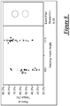
- FIG. 8 is a chart with testing data that compares the axial load distribution ratios of the tests performed for FIG. 7 . These tests showed a 33% improvement in axial load distribution ratios for the v-band clamp similar to the embodiment of FIG. 2 , compared to that for the known v-band clamps. These tests also showed a 5% decrease in total axial load for the v-band clamp similar to the embodiment of FIG. 2 , compared to that for the known v-band clamp; this decrease is deemed acceptable given the improvement in axial load distribution ratio. Of course, not all testing and experiments will yield this exact data.
- v-band clamp not necessarily shown in the figures can have different designs and constructions.
- the friction-reducing features of the embodiments of FIGS. 1 and 2 can be combined in a single v-band clamp; that is, a v-band clamp can have an unattached v-insert segment with angled side walls greater than those of attached v-insert segments.
Landscapes
- Engineering & Computer Science (AREA)
- General Engineering & Computer Science (AREA)
- Mechanical Engineering (AREA)
- Chemical & Material Sciences (AREA)
- Combustion & Propulsion (AREA)
- Clamps And Clips (AREA)
Claims (10)
- Collier de serrage en V (10) comprenant :une bande (12) s'étendant circonférentiellement d'une première extrémité (16) à une deuxième extrémité (18) ;un ensemble de loquet (14) situé au niveau desdites première et deuxième extrémités de ladite bande, ledit ensemble de loquet comprenant un dispositif de fixation utilisé pour serrer le collier de serrage en V ; etune pluralité de segments d'insertion en V (38, 40, 42, 44, 46, 138, 140, 142, 144, 146) situés radialement sous ladite bande (12) lorsque le collier de serrage en V est serré sur une paire de brides terminales de corps tubulaire ;un premier segment (38, 40, 138, 140) de ladite pluralité de segments d'insertion en V étant situé à une position circonférentielle de ladite bande (12) adjacente audit ensemble de loquet (14) et d'autres segments (42, 44, 46, 142, 144, 146) de ladite pluralité de segments d'insertion en V étant situés à une position circonférentielle de ladite bande (12) en éloignement dudit ensemble de loquet (14) ; etcaractérisé en ce que ledit premier segment d'insertion en V (38, 40, 138, 140), mais pas lesdits autres segments de ladite pluralité de segments d'insertion en V (42, 44, 46, 142, 144, 146) possède un élément de réduction de frottement qui réduit un frottement entre ledit segment d'insertion en V et la paire de brides terminales qui est généré lorsque le collier de serrage en V est serré sur la paire de brides terminales.
- Collier de serrage en V (10) de la revendication 1, dans lequel ledit élément de réduction de frottement est formé par le fait de laisser ledit premier segment d'insertion en V (38, 40, 138, 140) adjacent audit ensemble de loquet (14) détaché de ladite bande (12) tandis que lesdits autres segments de ladite pluralité de segments d'insertion en V (42, 44, 46, 142, 144, 146) situés à une position circonférentielle de ladite bande (12) en éloignement dudit ensemble de loquet (14) sont attachés à ladite bande (12).
- Collier de serrage en V (10) de la revendication 1 ou de la revendication 2, dans lequel lesdits autres segments de ladite pluralité de segments d'insertion en V (42, 44, 46, 142, 144, 146) sont attachés à ladite bande (12) par le biais d'au moins un point de soudure.
- Collier de serrage en V (10) de l'une quelconque des revendications précédentes, dans lequel ledit premier segment d'insertion en V (38, 40, 138, 140) est détaché de ladite bande (12) et demeure détaché de ladite bande lorsque le collier de serrage en V est serré sur la paire de brides terminales.
- Collier de serrage en V (10) de l'une quelconque des revendications précédentes, dans lequel ladite pluralité de segments d'insertion en V comprend deux segments (38, 40, 138, 140), chacun situé sous ladite bande (12) à une position circonférentielle adjacente audit ensemble de loquet (14), et dans lequel ledit élément de réduction de frottement comprend une mise en prise par glissement de ladite bande (12) avec lesdits deux segments (38, 40, 138, 140) de sorte que ladite bande (12) puisse bouger circonférentiellement pendant le serrage indépendamment desdits deux segments (38, 40, 138, 140).
- Collier de serrage en V (10) de l'une quelconque des revendications précédentes, dans lequel ledit élément de réduction de frottement est formé par le fait que ledit premier segment d'insertion en V (38, 40, 138, 140) adjacent audit ensemble de loquet (14) possède une paroi de base (62), une première paroi latérale (64) s'étendant depuis ladite paroi de base (62) et une deuxième paroi latérale (66) s'étendant depuis ladite paroi de base (62), lesdites première et deuxième parois latérales (64, 66) constituant un premier angle en profil en coupe transversale, et le fait que lesdits autres segments de ladite pluralité de segments d'insertion en V (42, 44, 46, 142, 144, 146) situés à une position circonférentielle de ladite bande (12) en éloignement dudit ensemble de loquet (14) possèdent une paroi de base (62), une première paroi latérale (64) s'étendant depuis ladite paroi de base (62) desdits autres segments de la pluralité de segments d'insertion en V et une deuxième paroi latérale (66) s'étendant depuis ladite paroi de base (62) desdits autres segments de la pluralité de segments d'insertion en V, lesdites première et deuxième parois latérales desdits autres segments de la pluralité de segments d'insertion en V constituant un deuxième angle en profil en coupe transversale, ledit deuxième angle ayant une valeur qui est plus petite que celle dudit premier angle.
- Collier de serrage en V de la revendication 6, dans lequel ledit premier angle a une valeur qui est d'environ 5° de plus que celle dudit deuxième angle.
- Collier de serrage en V de la revendication 6, dans lequel ledit premier angle a une valeur d'environ 55° et ledit deuxième angle a une valeur d'environ 40°.
- Collier de serrage en V de la revendication 6, dans lequel ledit premier angle a une valeur d'environ 70° et ledit deuxième angle a une valeur d'environ 55°.
- Collier de serrage en V de l'une quelconque des revendications 7 à 9, dans lequel lesdits autres segments de ladite pluralité de segments d'insertion en V (42, 44, 46, 142, 144, 146) sont attachés à ladite bande (12) et ledit premier segment d'insertion en V (38, 40, 138, 140) demeure détaché de ladite bande (12) ou attaché de façon lâche à celle-ci lorsque le collier de serrage en V est serré sur la paire de brides terminales de sorte que, pendant le serrage de ladite bande (12) par le biais dudit ensemble de loquet (14), ladite bande (12) puisse subir un mouvement circonférentiel par rapport audit premier segment d'insertion en V (38, 40, 138, 140).
Applications Claiming Priority (2)
| Application Number | Priority Date | Filing Date | Title |
|---|---|---|---|
| US201161504287P | 2011-07-04 | 2011-07-04 | |
| PCT/US2012/045477 WO2013006659A1 (fr) | 2011-07-04 | 2012-07-04 | Collier de serrage en v comportant des segments d'insertion en v |
Publications (3)
| Publication Number | Publication Date |
|---|---|
| EP2729708A1 EP2729708A1 (fr) | 2014-05-14 |
| EP2729708A4 EP2729708A4 (fr) | 2015-03-11 |
| EP2729708B1 true EP2729708B1 (fr) | 2019-04-17 |
Family
ID=47437427
Family Applications (1)
| Application Number | Title | Priority Date | Filing Date |
|---|---|---|---|
| EP12808092.6A Not-in-force EP2729708B1 (fr) | 2011-07-04 | 2012-07-04 | Collier de serrage en v comportant des segments d'insertion en v |
Country Status (5)
| Country | Link |
|---|---|
| US (1) | US9194523B2 (fr) |
| EP (1) | EP2729708B1 (fr) |
| KR (1) | KR101937726B1 (fr) |
| CN (1) | CN103732928B (fr) |
| WO (1) | WO2013006659A1 (fr) |
Cited By (1)
| Publication number | Priority date | Publication date | Assignee | Title |
|---|---|---|---|---|
| DE102020004800A1 (de) | 2020-08-07 | 2022-02-10 | Daimler Ag | Verbindungsschelle zum Verbinden zweier gegenüberliegender Rohrflansche |
Families Citing this family (19)
| Publication number | Priority date | Publication date | Assignee | Title |
|---|---|---|---|---|
| US20150165596A1 (en) * | 2013-10-16 | 2015-06-18 | Truston Technologies, Inc. | Strap and Tensioning Mechanism for Attaching Flotation Modules to Marine Structures, namely Port Security Barriers (PSBs) |
| CN104179565A (zh) * | 2014-08-13 | 2014-12-03 | 徐超 | 一种涡轮增压器分体环型箍带 |
| KR101633843B1 (ko) | 2015-02-12 | 2016-06-28 | 디에스에너텍 주식회사 | 기밀 부재 일체형 브이 밴드클램프 및 브이 밴드클램프용 기밀 부재 코킹장치 |
| JP6567307B2 (ja) * | 2015-03-27 | 2019-08-28 | 株式会社Subaru | Vバンド |
| WO2017095683A1 (fr) * | 2015-11-30 | 2017-06-08 | Norma U.S. Holding Llc | Collier de serrage de tuyau |
| US10723080B1 (en) * | 2016-01-22 | 2020-07-28 | Infiltrator Water Technologies, Llc | Making a plastic tank having a weld joint by using a resilient clamp |
| US9968188B1 (en) | 2016-07-11 | 2018-05-15 | Engineered Network Systems, Llc | Locking base for tablet stand |
| WO2018165332A1 (fr) | 2017-03-07 | 2018-09-13 | Norma U.S. Holding Llc | Collier de serrage de tuyau et raccord de tuyau avec logement de capteur |
| EP3724516B1 (fr) | 2017-12-14 | 2026-04-22 | Cummins, Inc. | Système de serrage |
| DE102018111539A1 (de) * | 2018-05-15 | 2019-11-21 | Norma Germany Gmbh | Profilschelle |
| JP6983113B2 (ja) * | 2018-06-07 | 2021-12-17 | 本田技研工業株式会社 | 排気系部品締結構造 |
| DE102018116959A1 (de) * | 2018-07-12 | 2020-01-16 | Norma Germany Gmbh | Profilschelle |
| US11512737B2 (en) | 2019-02-28 | 2022-11-29 | Norma U.S. Holding Llc | V-clamp with more evenly distributed clamping load |
| DE102019109196A1 (de) * | 2019-04-08 | 2020-10-08 | Norma Germany Gmbh | Flexibel einsetzbare Profilschelle |
| CN114270087B (zh) * | 2019-07-31 | 2025-04-08 | 诺玛美国控股有限责任公司 | 接合组件、v形夹具和端部凸缘 |
| WO2021022013A1 (fr) * | 2019-07-31 | 2021-02-04 | Norma U.S. Holding Llc | Ensemble raccord, collier en v, et brides d'extrémité |
| US11808293B2 (en) | 2021-02-25 | 2023-11-07 | Bae Systems Information And Electronic Systems Integration Inc. | V-band clamp |
| WO2022204089A1 (fr) * | 2021-03-22 | 2022-09-29 | Norma U.S. Holding Llc | Raccord doté d'au moins une fenêtre de visualisation de soudure par points par résistance |
| GB2618851A (en) * | 2022-05-20 | 2023-11-22 | Cooke Howard S & Co Ltd | A method of assembling a latching assembly, a latch and a band clamp |
Family Cites Families (15)
| Publication number | Priority date | Publication date | Assignee | Title |
|---|---|---|---|---|
| US2842385A (en) * | 1953-03-24 | 1958-07-08 | Aeroquip Corp | Band clamp with slip-band constrictor means |
| GB738141A (en) | 1953-03-26 | 1955-10-05 | Marman Products Company Inc | Improvements in tube couplings |
| US2841420A (en) * | 1956-04-24 | 1958-07-01 | Aeroquip Corp | V-band clamp with clamping band and combined guide and bracing yokes |
| US3019036A (en) * | 1959-02-24 | 1962-01-30 | Gen Electric | Retractable flange coupling unit |
| US3010172A (en) * | 1960-03-02 | 1961-11-28 | Poly Ind Inc | Integrally reinforced v-band clamp |
| US3861723A (en) * | 1973-08-28 | 1975-01-21 | Us Air Force | V-band coupling |
| US4527818A (en) | 1981-02-17 | 1985-07-09 | Texaco Inc. | Coupling for pipe or tubing |
| CA2079404A1 (fr) | 1991-10-09 | 1993-04-10 | Oded Yehezkeli | Pince |
| JP2000009276A (ja) * | 1998-06-24 | 2000-01-11 | Sakamoto:Kk | ダクト接続装置 |
| CN2387362Y (zh) * | 1999-09-28 | 2000-07-12 | 南京晨光东螺波纹管有限公司 | 低压管道法兰连接用“v”形夹 |
| US7320485B2 (en) * | 2003-10-16 | 2008-01-22 | Breeze-Torca Products, Llc | V insert edge contour |
| US7086131B2 (en) * | 2004-05-14 | 2006-08-08 | Victaulic Company | Deformable mechanical pipe coupling |
| US20050264010A1 (en) * | 2004-05-27 | 2005-12-01 | Wagner Wayne M | V-band clamp |
| KR20080014734A (ko) * | 2005-03-04 | 2008-02-14 | 브리즈-토르카 프로덕츠 엘엘씨 | V-링 인서트를 가진 파이프 클램프 조립체 |
| US8454056B2 (en) * | 2011-07-28 | 2013-06-04 | Senior Investments Gmbh | Double strap coupling apparatus |
-
2012
- 2012-07-04 US US13/541,741 patent/US9194523B2/en active Active
- 2012-07-04 KR KR1020147002908A patent/KR101937726B1/ko not_active Expired - Fee Related
- 2012-07-04 EP EP12808092.6A patent/EP2729708B1/fr not_active Not-in-force
- 2012-07-04 WO PCT/US2012/045477 patent/WO2013006659A1/fr not_active Ceased
- 2012-07-04 CN CN201280040467.8A patent/CN103732928B/zh active Active
Non-Patent Citations (1)
| Title |
|---|
| None * |
Cited By (1)
| Publication number | Priority date | Publication date | Assignee | Title |
|---|---|---|---|---|
| DE102020004800A1 (de) | 2020-08-07 | 2022-02-10 | Daimler Ag | Verbindungsschelle zum Verbinden zweier gegenüberliegender Rohrflansche |
Also Published As
| Publication number | Publication date |
|---|---|
| US9194523B2 (en) | 2015-11-24 |
| WO2013006659A1 (fr) | 2013-01-10 |
| EP2729708A4 (fr) | 2015-03-11 |
| KR20140046010A (ko) | 2014-04-17 |
| CN103732928B (zh) | 2016-11-09 |
| KR101937726B1 (ko) | 2019-01-11 |
| US20130174384A1 (en) | 2013-07-11 |
| EP2729708A1 (fr) | 2014-05-14 |
| CN103732928A (zh) | 2014-04-16 |
Similar Documents
| Publication | Publication Date | Title |
|---|---|---|
| EP2729708B1 (fr) | Collier de serrage en v comportant des segments d'insertion en v | |
| US7770937B2 (en) | Stepped ball joint pipe clamp and pre-attachment components therefor | |
| EP2526330B1 (fr) | Collier de serrage ayant joint d'étanchéité | |
| EP2245358B1 (fr) | Serre-joint à sangle à boulon unique doté d'une nervure centrale à joints et joint à recouvrement de tuyau utilisant le serre-joint | |
| US4506418A (en) | Muffler clamp | |
| EP1825181B1 (fr) | Collier de serrage de tuyau comprenant un element de fixation ameliore | |
| EP2594835A1 (fr) | Collier de raccord à profil en V | |
| EP1797363B1 (fr) | Joint a recouvrement pour tuyaux ayant une meilleure fente d'etancheite pour une fermeture circonferentielle amelioree | |
| US20160053783A1 (en) | Retaining clamp with interconnected segments | |
| JP4988246B2 (ja) | パイプと板材との接合方法 | |
| CA2999727C (fr) | Pince | |
| KR20250126713A (ko) | 구속용 t-볼트를 구비한 퀵-래치 클램프 |
Legal Events
| Date | Code | Title | Description |
|---|---|---|---|
| PUAI | Public reference made under article 153(3) epc to a published international application that has entered the european phase |
Free format text: ORIGINAL CODE: 0009012 |
|
| 17P | Request for examination filed |
Effective date: 20140204 |
|
| AK | Designated contracting states |
Kind code of ref document: A1 Designated state(s): AL AT BE BG CH CY CZ DE DK EE ES FI FR GB GR HR HU IE IS IT LI LT LU LV MC MK MT NL NO PL PT RO RS SE SI SK SM TR |
|
| DAX | Request for extension of the european patent (deleted) | ||
| RIC1 | Information provided on ipc code assigned before grant |
Ipc: F16B 2/10 20060101ALI20150127BHEP Ipc: F16B 2/08 20060101AFI20150127BHEP |
|
| A4 | Supplementary search report drawn up and despatched |
Effective date: 20150209 |
|
| RIC1 | Information provided on ipc code assigned before grant |
Ipc: F16B 2/10 20060101ALI20150203BHEP Ipc: F16B 2/08 20060101AFI20150203BHEP |
|
| STAA | Information on the status of an ep patent application or granted ep patent |
Free format text: STATUS: EXAMINATION IS IN PROGRESS |
|
| RIN1 | Information on inventor provided before grant (corrected) |
Inventor name: IGNACZAK, BRIAN, T. Inventor name: LJULJDUROVIC, MILAN Inventor name: CHEN, ALEX, Y. |
|
| 17Q | First examination report despatched |
Effective date: 20171116 |
|
| REG | Reference to a national code |
Ref country code: DE Ref legal event code: R079 Ref document number: 602012059138 Country of ref document: DE Free format text: PREVIOUS MAIN CLASS: F16B0002080000 Ipc: F16L0023100000 |
|
| GRAP | Despatch of communication of intention to grant a patent |
Free format text: ORIGINAL CODE: EPIDOSNIGR1 |
|
| STAA | Information on the status of an ep patent application or granted ep patent |
Free format text: STATUS: GRANT OF PATENT IS INTENDED |
|
| RIC1 | Information provided on ipc code assigned before grant |
Ipc: F16L 23/10 20060101AFI20180928BHEP Ipc: F01N 13/18 20100101ALI20180928BHEP |
|
| INTG | Intention to grant announced |
Effective date: 20181026 |
|
| GRAS | Grant fee paid |
Free format text: ORIGINAL CODE: EPIDOSNIGR3 |
|
| GRAA | (expected) grant |
Free format text: ORIGINAL CODE: 0009210 |
|
| STAA | Information on the status of an ep patent application or granted ep patent |
Free format text: STATUS: THE PATENT HAS BEEN GRANTED |
|
| AK | Designated contracting states |
Kind code of ref document: B1 Designated state(s): AL AT BE BG CH CY CZ DE DK EE ES FI FR GB GR HR HU IE IS IT LI LT LU LV MC MK MT NL NO PL PT RO RS SE SI SK SM TR |
|
| REG | Reference to a national code |
Ref country code: GB Ref legal event code: FG4D |
|
| REG | Reference to a national code |
Ref country code: CH Ref legal event code: EP |
|
| REG | Reference to a national code |
Ref country code: DE Ref legal event code: R096 Ref document number: 602012059138 Country of ref document: DE |
|
| REG | Reference to a national code |
Ref country code: AT Ref legal event code: REF Ref document number: 1121912 Country of ref document: AT Kind code of ref document: T Effective date: 20190515 Ref country code: IE Ref legal event code: FG4D |
|
| REG | Reference to a national code |
Ref country code: SE Ref legal event code: TRGR |
|
| REG | Reference to a national code |
Ref country code: NL Ref legal event code: FP |
|
| REG | Reference to a national code |
Ref country code: LT Ref legal event code: MG4D |
|
| PG25 | Lapsed in a contracting state [announced via postgrant information from national office to epo] |
Ref country code: ES Free format text: LAPSE BECAUSE OF FAILURE TO SUBMIT A TRANSLATION OF THE DESCRIPTION OR TO PAY THE FEE WITHIN THE PRESCRIBED TIME-LIMIT Effective date: 20190417 Ref country code: LT Free format text: LAPSE BECAUSE OF FAILURE TO SUBMIT A TRANSLATION OF THE DESCRIPTION OR TO PAY THE FEE WITHIN THE PRESCRIBED TIME-LIMIT Effective date: 20190417 Ref country code: FI Free format text: LAPSE BECAUSE OF FAILURE TO SUBMIT A TRANSLATION OF THE DESCRIPTION OR TO PAY THE FEE WITHIN THE PRESCRIBED TIME-LIMIT Effective date: 20190417 Ref country code: HR Free format text: LAPSE BECAUSE OF FAILURE TO SUBMIT A TRANSLATION OF THE DESCRIPTION OR TO PAY THE FEE WITHIN THE PRESCRIBED TIME-LIMIT Effective date: 20190417 Ref country code: NO Free format text: LAPSE BECAUSE OF FAILURE TO SUBMIT A TRANSLATION OF THE DESCRIPTION OR TO PAY THE FEE WITHIN THE PRESCRIBED TIME-LIMIT Effective date: 20190717 Ref country code: AL Free format text: LAPSE BECAUSE OF FAILURE TO SUBMIT A TRANSLATION OF THE DESCRIPTION OR TO PAY THE FEE WITHIN THE PRESCRIBED TIME-LIMIT Effective date: 20190417 Ref country code: PT Free format text: LAPSE BECAUSE OF FAILURE TO SUBMIT A TRANSLATION OF THE DESCRIPTION OR TO PAY THE FEE WITHIN THE PRESCRIBED TIME-LIMIT Effective date: 20190817 |
|
| PG25 | Lapsed in a contracting state [announced via postgrant information from national office to epo] |
Ref country code: GR Free format text: LAPSE BECAUSE OF FAILURE TO SUBMIT A TRANSLATION OF THE DESCRIPTION OR TO PAY THE FEE WITHIN THE PRESCRIBED TIME-LIMIT Effective date: 20190718 Ref country code: PL Free format text: LAPSE BECAUSE OF FAILURE TO SUBMIT A TRANSLATION OF THE DESCRIPTION OR TO PAY THE FEE WITHIN THE PRESCRIBED TIME-LIMIT Effective date: 20190417 Ref country code: LV Free format text: LAPSE BECAUSE OF FAILURE TO SUBMIT A TRANSLATION OF THE DESCRIPTION OR TO PAY THE FEE WITHIN THE PRESCRIBED TIME-LIMIT Effective date: 20190417 Ref country code: BG Free format text: LAPSE BECAUSE OF FAILURE TO SUBMIT A TRANSLATION OF THE DESCRIPTION OR TO PAY THE FEE WITHIN THE PRESCRIBED TIME-LIMIT Effective date: 20190717 Ref country code: RS Free format text: LAPSE BECAUSE OF FAILURE TO SUBMIT A TRANSLATION OF THE DESCRIPTION OR TO PAY THE FEE WITHIN THE PRESCRIBED TIME-LIMIT Effective date: 20190417 |
|
| REG | Reference to a national code |
Ref country code: AT Ref legal event code: MK05 Ref document number: 1121912 Country of ref document: AT Kind code of ref document: T Effective date: 20190417 |
|
| PG25 | Lapsed in a contracting state [announced via postgrant information from national office to epo] |
Ref country code: IS Free format text: LAPSE BECAUSE OF FAILURE TO SUBMIT A TRANSLATION OF THE DESCRIPTION OR TO PAY THE FEE WITHIN THE PRESCRIBED TIME-LIMIT Effective date: 20190817 |
|
| REG | Reference to a national code |
Ref country code: DE Ref legal event code: R097 Ref document number: 602012059138 Country of ref document: DE |
|
| PG25 | Lapsed in a contracting state [announced via postgrant information from national office to epo] |
Ref country code: DK Free format text: LAPSE BECAUSE OF FAILURE TO SUBMIT A TRANSLATION OF THE DESCRIPTION OR TO PAY THE FEE WITHIN THE PRESCRIBED TIME-LIMIT Effective date: 20190417 Ref country code: AT Free format text: LAPSE BECAUSE OF FAILURE TO SUBMIT A TRANSLATION OF THE DESCRIPTION OR TO PAY THE FEE WITHIN THE PRESCRIBED TIME-LIMIT Effective date: 20190417 Ref country code: EE Free format text: LAPSE BECAUSE OF FAILURE TO SUBMIT A TRANSLATION OF THE DESCRIPTION OR TO PAY THE FEE WITHIN THE PRESCRIBED TIME-LIMIT Effective date: 20190417 Ref country code: CZ Free format text: LAPSE BECAUSE OF FAILURE TO SUBMIT A TRANSLATION OF THE DESCRIPTION OR TO PAY THE FEE WITHIN THE PRESCRIBED TIME-LIMIT Effective date: 20190417 Ref country code: RO Free format text: LAPSE BECAUSE OF FAILURE TO SUBMIT A TRANSLATION OF THE DESCRIPTION OR TO PAY THE FEE WITHIN THE PRESCRIBED TIME-LIMIT Effective date: 20190417 Ref country code: SK Free format text: LAPSE BECAUSE OF FAILURE TO SUBMIT A TRANSLATION OF THE DESCRIPTION OR TO PAY THE FEE WITHIN THE PRESCRIBED TIME-LIMIT Effective date: 20190417 |
|
| PLBE | No opposition filed within time limit |
Free format text: ORIGINAL CODE: 0009261 |
|
| STAA | Information on the status of an ep patent application or granted ep patent |
Free format text: STATUS: NO OPPOSITION FILED WITHIN TIME LIMIT |
|
| PG25 | Lapsed in a contracting state [announced via postgrant information from national office to epo] |
Ref country code: SM Free format text: LAPSE BECAUSE OF FAILURE TO SUBMIT A TRANSLATION OF THE DESCRIPTION OR TO PAY THE FEE WITHIN THE PRESCRIBED TIME-LIMIT Effective date: 20190417 Ref country code: MC Free format text: LAPSE BECAUSE OF FAILURE TO SUBMIT A TRANSLATION OF THE DESCRIPTION OR TO PAY THE FEE WITHIN THE PRESCRIBED TIME-LIMIT Effective date: 20190417 |
|
| REG | Reference to a national code |
Ref country code: CH Ref legal event code: PL |
|
| 26N | No opposition filed |
Effective date: 20200120 |
|
| PG25 | Lapsed in a contracting state [announced via postgrant information from national office to epo] |
Ref country code: TR Free format text: LAPSE BECAUSE OF FAILURE TO SUBMIT A TRANSLATION OF THE DESCRIPTION OR TO PAY THE FEE WITHIN THE PRESCRIBED TIME-LIMIT Effective date: 20190417 |
|
| REG | Reference to a national code |
Ref country code: BE Ref legal event code: MM Effective date: 20190731 |
|
| PG25 | Lapsed in a contracting state [announced via postgrant information from national office to epo] |
Ref country code: LU Free format text: LAPSE BECAUSE OF NON-PAYMENT OF DUE FEES Effective date: 20190704 Ref country code: BE Free format text: LAPSE BECAUSE OF NON-PAYMENT OF DUE FEES Effective date: 20190731 Ref country code: CH Free format text: LAPSE BECAUSE OF NON-PAYMENT OF DUE FEES Effective date: 20190731 Ref country code: LI Free format text: LAPSE BECAUSE OF NON-PAYMENT OF DUE FEES Effective date: 20190731 Ref country code: SI Free format text: LAPSE BECAUSE OF FAILURE TO SUBMIT A TRANSLATION OF THE DESCRIPTION OR TO PAY THE FEE WITHIN THE PRESCRIBED TIME-LIMIT Effective date: 20190417 |
|
| PG25 | Lapsed in a contracting state [announced via postgrant information from national office to epo] |
Ref country code: IE Free format text: LAPSE BECAUSE OF NON-PAYMENT OF DUE FEES Effective date: 20190704 |
|
| PG25 | Lapsed in a contracting state [announced via postgrant information from national office to epo] |
Ref country code: CY Free format text: LAPSE BECAUSE OF FAILURE TO SUBMIT A TRANSLATION OF THE DESCRIPTION OR TO PAY THE FEE WITHIN THE PRESCRIBED TIME-LIMIT Effective date: 20190417 |
|
| PG25 | Lapsed in a contracting state [announced via postgrant information from national office to epo] |
Ref country code: MT Free format text: LAPSE BECAUSE OF FAILURE TO SUBMIT A TRANSLATION OF THE DESCRIPTION OR TO PAY THE FEE WITHIN THE PRESCRIBED TIME-LIMIT Effective date: 20190417 Ref country code: HU Free format text: LAPSE BECAUSE OF FAILURE TO SUBMIT A TRANSLATION OF THE DESCRIPTION OR TO PAY THE FEE WITHIN THE PRESCRIBED TIME-LIMIT; INVALID AB INITIO Effective date: 20120704 |
|
| PG25 | Lapsed in a contracting state [announced via postgrant information from national office to epo] |
Ref country code: MK Free format text: LAPSE BECAUSE OF FAILURE TO SUBMIT A TRANSLATION OF THE DESCRIPTION OR TO PAY THE FEE WITHIN THE PRESCRIBED TIME-LIMIT Effective date: 20190417 |
|
| PGFP | Annual fee paid to national office [announced via postgrant information from national office to epo] |
Ref country code: NL Payment date: 20220726 Year of fee payment: 11 |
|
| PGFP | Annual fee paid to national office [announced via postgrant information from national office to epo] |
Ref country code: SE Payment date: 20220727 Year of fee payment: 11 Ref country code: IT Payment date: 20220721 Year of fee payment: 11 |
|
| REG | Reference to a national code |
Ref country code: SE Ref legal event code: EUG |
|
| REG | Reference to a national code |
Ref country code: NL Ref legal event code: MM Effective date: 20230801 |
|
| PG25 | Lapsed in a contracting state [announced via postgrant information from national office to epo] |
Ref country code: NL Free format text: LAPSE BECAUSE OF NON-PAYMENT OF DUE FEES Effective date: 20230801 |
|
| PG25 | Lapsed in a contracting state [announced via postgrant information from national office to epo] |
Ref country code: NL Free format text: LAPSE BECAUSE OF NON-PAYMENT OF DUE FEES Effective date: 20230801 |
|
| PG25 | Lapsed in a contracting state [announced via postgrant information from national office to epo] |
Ref country code: SE Free format text: LAPSE BECAUSE OF NON-PAYMENT OF DUE FEES Effective date: 20230705 |
|
| PG25 | Lapsed in a contracting state [announced via postgrant information from national office to epo] |
Ref country code: IT Free format text: LAPSE BECAUSE OF NON-PAYMENT OF DUE FEES Effective date: 20230704 |
|
| PGFP | Annual fee paid to national office [announced via postgrant information from national office to epo] |
Ref country code: DE Payment date: 20240729 Year of fee payment: 13 |
|
| PGFP | Annual fee paid to national office [announced via postgrant information from national office to epo] |
Ref country code: GB Payment date: 20240729 Year of fee payment: 13 |
|
| PGFP | Annual fee paid to national office [announced via postgrant information from national office to epo] |
Ref country code: FR Payment date: 20240725 Year of fee payment: 13 |
|
| REG | Reference to a national code |
Ref country code: DE Ref legal event code: R119 Ref document number: 602012059138 Country of ref document: DE |
|
| GBPC | Gb: european patent ceased through non-payment of renewal fee |
Effective date: 20250704 |
|
| PG25 | Lapsed in a contracting state [announced via postgrant information from national office to epo] |
Ref country code: GB Free format text: LAPSE BECAUSE OF NON-PAYMENT OF DUE FEES Effective date: 20250704 |
|
| PG25 | Lapsed in a contracting state [announced via postgrant information from national office to epo] |
Ref country code: DE Free format text: LAPSE BECAUSE OF NON-PAYMENT OF DUE FEES Effective date: 20260203 |
|
| PG25 | Lapsed in a contracting state [announced via postgrant information from national office to epo] |
Ref country code: FR Free format text: LAPSE BECAUSE OF NON-PAYMENT OF DUE FEES Effective date: 20250731 |