EP2729836B1 - Dispositif de terminaison de réseau pour réseaux optiques - Google Patents
Dispositif de terminaison de réseau pour réseaux optiques Download PDFInfo
- Publication number
- EP2729836B1 EP2729836B1 EP11797303.2A EP11797303A EP2729836B1 EP 2729836 B1 EP2729836 B1 EP 2729836B1 EP 11797303 A EP11797303 A EP 11797303A EP 2729836 B1 EP2729836 B1 EP 2729836B1
- Authority
- EP
- European Patent Office
- Prior art keywords
- network termination
- base unit
- cover
- combination according
- termination terminal
- Prior art date
- Legal status (The legal status is an assumption and is not a legal conclusion. Google has not performed a legal analysis and makes no representation as to the accuracy of the status listed.)
- Active
Links
Images


Classifications
-
- G—PHYSICS
- G02—OPTICS
- G02B—OPTICAL ELEMENTS, SYSTEMS OR APPARATUS
- G02B6/00—Light guides; Structural details of arrangements comprising light guides and other optical elements, e.g. couplings
- G02B6/46—Processes or apparatus adapted for installing or repairing optical fibres or optical cables
- G02B6/47—Installation in buildings
- G02B6/475—Mechanical aspects of installing cables in ducts or the like for buildings
-
- G—PHYSICS
- G02—OPTICS
- G02B—OPTICAL ELEMENTS, SYSTEMS OR APPARATUS
- G02B6/00—Light guides; Structural details of arrangements comprising light guides and other optical elements, e.g. couplings
- G02B6/44—Mechanical structures for providing tensile strength and external protection for fibres, e.g. optical transmission cables
- G02B6/4439—Auxiliary devices
- G02B6/444—Systems or boxes with surplus lengths
- G02B6/4441—Boxes
-
- G—PHYSICS
- G02—OPTICS
- G02B—OPTICAL ELEMENTS, SYSTEMS OR APPARATUS
- G02B6/00—Light guides; Structural details of arrangements comprising light guides and other optical elements, e.g. couplings
- G02B6/44—Mechanical structures for providing tensile strength and external protection for fibres, e.g. optical transmission cables
- G02B6/4439—Auxiliary devices
- G02B6/444—Systems or boxes with surplus lengths
- G02B6/44528—Patch-cords; Connector arrangements in the system or in the box
-
- G—PHYSICS
- G02—OPTICS
- G02B—OPTICAL ELEMENTS, SYSTEMS OR APPARATUS
- G02B6/00—Light guides; Structural details of arrangements comprising light guides and other optical elements, e.g. couplings
- G02B6/44—Mechanical structures for providing tensile strength and external protection for fibres, e.g. optical transmission cables
- G02B6/4439—Auxiliary devices
- G02B6/444—Systems or boxes with surplus lengths
- G02B6/4441—Boxes
- G02B6/4446—Cable boxes, e.g. splicing boxes with two or more multi fibre cables
- G02B6/44465—Seals
Definitions
- the present invention relates to a network termination device for optical networks according to the preamble of claim 1.
- the device comprises a base unit in which one or more optical fibers can be received, which are in particular in the form of one or more fiber optic cable ends.
- the device has a cover, by means of which the base unit can be covered and / or closed with the fibers or cables received therein.
- a network termination terminal can be received or attached to the base unit.
- This network termination terminal in turn comprises at least one user module for one or more services desired by an end user, for example for a telephone connection, a television connection or a data exchange connection, in particular an Internet connection.
- Such devices are insofar intended and suitable for FTTH ("Fiber to the home") or in particular for use in premises of end consumers.
- the rooms can also be an office or public or commercial space.
- ONT Optical Network Terminal
- further devices can be connected to the optical waveguide fibers in the premises of the end user, wherein the modules of the network termination terminals receive the optical signals received via the fibers convert into signals that are appropriate for each device.
- the base unit of the network termination device can preferably be mounted on a wall surface. Only at a later date, the device is then supplemented by a suitable network termination terminal.
- the network termination terminal is customizable with the modules required for the desired services to the respective wishes of the user. It can easily be connected to a fiber end of the network termination device and also easily attached to the base unit. If necessary, a simple exchange is possible against another network termination terminal.
- a network termination package for optical network termination comprises a fiber box in which in a first area at least one fiber optic cable of sufficient length is received wrapped in one or more loops. In a second area of the fiber box, the end of the at least one fiber optic cable is laid with connectors or connectors for later further wiring, the plug can be accommodated in dust caps.
- the fiber box is closed by a lid, which can also be sealed if necessary.
- US2011249941 discloses an optical network device comprising a base unit for receiving optical fibers, a lid, a wall box, and optical fiber connectors with labels.
- US2010129028 discloses a network termination device for optical networks and at least one network terminating terminal attachable thereto, with a lid, and means for attachment.
- the network termination terminal has an identifier that is visible through a recess of the lid.
- the actual optical network termination can be retrofitted without further construction measures.
- This is then a separate, so-called Netzab gleichbox, in which one or more user modules for one or more services requested by the customer with corresponding connection sockets, on the fiber box put on and anchored.
- the end of the at least one fiber optic cable with the connectors located thereon is brought out by opening an extra lid provided in the lid for this purpose from the base or fiber box and into the Netzab gleichbox and connected there to prepared internal plug-in connections.
- Object of the present invention is to provide a structurally simple and easy to handle network termination device for optical networks of the type mentioned, which allows a particularly simple activation or activation of certain desired by the end user services.
- the base unit has an identifier by which the network termination of the end user can be clearly identified, and that the identifier is mounted in such a way that it is easily recognizable even when an attached network termination terminal from the outside.
- the identifier is thus arranged so that it is not covered by a later to be mounted on the means provided for network termination terminal.
- the main advantage lies in the fact that regardless of the type of network termination terminals to be attached for the desired services, a unique identification of the customer connection can be easily and quickly read and reused at any time, without the need for additional resources or the network termination terminal of the base unit must be removed. Therefore, the user can easily enter or specify the identifier data that is readily recognizable at any time for activating or activating the connection or specific services at this connection in an input field or dialog provided for this purpose.
- services booked within the framework of an existing contractual relationship can easily be activated at another connection in another building by reading the new connection identifier and, in particular, correspondingly reusing it in connection with customer data.
- the network termination device is inexpensive to manufacture with a simple construction and easy to assemble and handle.
- the network termination terminal has in its housing a recess through which the identifier of the base unit is visible when the network termination terminal is attached to the base unit.
- the recess may be formed both in the region of a housing edge as open to the outside recess or in the form of a surrounding surrounding the housing window.
- the cover has a corresponding recess through which the identifier of the base unit is visible when the lid is attached to the base unit to cover or close it.
- the recesses may be designed to be open as a breakthrough in a particularly simple embodiment. However, it is preferred that the recess in the lid and / or in the housing of the network termination terminal is filled with a transparent or transparent material. In this way, in particular the penetration of dust can be prevented.
- a particularly convenient embodiment for the end user can be achieved in that the identifier of the terminal is mounted in an upper portion of the base unit, being advantageously oriented so as to be inclined from above, i. at a preferably acute angle to the wall surface on which the base unit is mounted, can be seen and read.
- the network termination terminal can only be attached to the base unit with the cover removed, preferably mounted in a form-fitting and / or force-fitting manner thereto.
- the cover has at least approximately the same shape and size as the housing of the network termination terminal.
- the lid may also be cup-shaped and sized so that the net terminating terminal between the base unit and the lid, preferably can be completely received in the lid.
- the lid is connected via a hinge-like connection pivotally connected to the base unit, so that the lid can not be lost.
- the lid is made in one piece with the base unit.
- the network termination terminal can be covered or closed by the lid when attached to the base unit.
- the cover can have at least one opening through which cables can be connected to a network termination terminal when the cover is attached, which is attached to the base unit and covered by the cover.
- a plurality of openings are provided in front of the connection sockets of the network termination terminal, so that in each case a separate opening in the lid is arranged for a plurality of cables to be connected, which makes the connection easier for laymen.
- connection of cables can be carried out particularly easily if the walls of the openings provided in the cover are in the form of an obliquely or conically tapering guide which leads to the connection sockets of the network termination terminal, so that the plug is also "blind” from below can be inserted and safely plugged.
- other components such as an external power supply or other devices or systems, even then be conveniently and quickly connected in downward-opening sockets of the network termination terminal when the base unit is relatively far below or just above the ground mounted on a wall.
- At least one connecting device is provided on the base unit, by which a terminating in the base unit fiber cable can be connected to another cable.
- a holding device can advantageously be provided at the base station, in which regions of optical fibers which are interconnected by a splice connection can be accommodated, in particular in a clamping manner, in order to keep the splice connection free of possible tensile load stresses.
- the base unit has at least one holding device, by means of which optical fibers which are present in the form of a glass fiber cable end with a plug mounted thereon can be held in a form-fitting and / or non-positive manner.
- the holding device is formed by at least one cable clamp, in which the fiber optic cable is clamped. Later, the fiber optic cable can also be detached from non-specialist personnel as far as necessary from the holding device and the plug can then be connected to an ONT.
- the holding device comprises a receptacle with a protective cap for the free contact region of the plug mounted on the optical fiber cable end, wherein the protective cap is attached to the receptacle so that it remains on the receptacle, even if the plug for connection an ONT is taken from the recording. The connection is made even easier.
- the plug mounted on the optical fiber cable end may be self-locking to prevent inadvertent removal from an ONT.
- the subject of the present invention is further a combination consisting of a network termination device of the type described above and at least one network termination terminal which can be attached thereto.
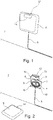
- the network termination device 1 shown in the figures is mounted on a room wall 2 in a room of an end user in preparation for a fiber optic connection designed as FTTH.
- the network termination device 1 comprises a base unit 3, on which in a manner known per se a fiber optic cable 5 wound up in one or more windings 4 is accommodated.
- the base unit 3 is initially covered by the cable 5 accommodated therein by a removable cover 6 which is attached to the base unit 3 in a positive and non-positive manner ( FIG. 1 ).
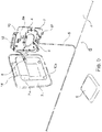
- the cover 6 can also be hingedly connected to the base unit 3 ( FIGS. 6 and 7).
- a network termination terminal (ONT) 7 is connected to the network termination thus prepared to attach to the base unit 3.
- the cover 6 is first removed from the base unit 3 ( FIG. 2 ) or unfolded ( FIG. 6 ) and the previously held in particular in cable clamps 8a clamped cable end solved with the already mounted thereon connector 8.
- An optional protective cap 9 placed on the plug cap 9 is also removed, so that the plug 8 can be plugged into a corresponding socket 7a of the network termination terminal 7 ( FIG. 3 ).
- the network termination terminal 7 with the fiber optic cable 5 connected thereto is mounted on the base unit 3 ( FIGS. 4 and 7 ).
- two or three fastening means 10 designed in the form of holding pins are provided on the base unit 3, which engage positively and non-positively in corresponding recesses 10a of the network termination terminal 7 (FIG. Figures 2 . 3 and 6 ).
- the fastening means 10 are formed by four elastically resilient latching lugs which engage in the insertion of the net terminating terminal 7 into four correspondingly formed recesses 10a.
- the optical connections are in the embodiments of FIGS. 1 to 5 hidden behind the network termination terminal 7, so that damage to the glass fiber can be avoided.
- connection sockets 11 are connected, which are arranged on the underside of the network termination terminal 7.
- a label 12 is attached to the base unit 3, via which the network termination device 1 of the end user can be uniquely identified.
- This identifier 12 for example, a telephone number, is applied in the illustrated embodiment inextricably on a tab 13 which protrudes at the upper edge of the base unit 3 of the voltage applied to the wall 2 base surface of the base unit 3.
- the tab 13 has a V-shaped upwardly angled tongue on which the identifier 12 is located so that it can be conveniently read from an obliquely upward viewing direction.
- Both in the cover 6 and in the network termination terminal 7 each have a recess 14 is formed, which is filled in the form of a window with transparent plastic. Through these window-like recesses 14 through the present on the base unit 3 identifier 12 can then be easily recognized and read from the outside, when the lid 6 and / or the network termination terminal 7 is attached to the base unit 3.
- the cover is hingedly connected to the base unit 3 by means of a hinge device 15.
- locking means 16 are provided on the hinge 15 opposite side.
- the recess 14 is executed here borderless in the region of the upper edge of the lid 6. But even this outwardly open recess 14 is also filled by a transparent plastic disc 14a.
- the fiber optic cable 5 entering from below into the base unit initially extends through a cable clamp 17 for strain relief. Subsequently, it is wound around two cylindrical projections 19 provided with retaining lugs 18, which serve as a spindle for receiving excess cable length.
- the plug 8 mounted at the free end of the glass fiber cable is held in a force-fitting manner in a holding device 20 provided on the base unit 3, from which it can be easily removed for connecting a network termination terminal 7.
- the holding device 20 comprises a receptacle 21 with an integrated therein protective cap for the free contact region of the plug 8. When removing the plug 8 from the receptacle 21, the cap thus remains captive in the receptacle 21st
- the cover 6 In its lower region, the cover 6 has two openings 22a and 22b, which lie in the closed lid position in front of the connection sockets 11 arranged at the bottom of the network termination terminal 7.
- a LAN cable 11a and an external power supply 11b may be connected through the respective openings 22a and 22b with the lid 6 closed to a network termination terminal 7. Unintentional opening of the lid 6 with cables 11a, 11b still inserted into the network terminating terminal 7 can thus be prevented.
- a holding device formed by two cable clamps 23 is provided here at the base station 3 in order to be able to absorb a possibly spliced connection with a load-relieved load.
Landscapes
- Physics & Mathematics (AREA)
- General Physics & Mathematics (AREA)
- Optics & Photonics (AREA)
- Engineering & Computer Science (AREA)
- Civil Engineering (AREA)
- Structural Engineering (AREA)
- Light Guides In General And Applications Therefor (AREA)
Claims (13)
- Combinaison d'un système de terminaison de réseau (1) destiné à des réseaux optiques et d'au moins terminal de terminaison de réseau (7) susceptible d'être monté sur celui-ci, lequel comprend au moins un module d'abonné pour un ou pour plusieurs services,
le système de terminaison de réseau (1) comprenant
une unité de base (3), destinée à recevoir une ou plusieurs fibres optiques (5), notamment une extrémité de câble optique,
un couvercle (6), permettant de recouvrir ou de fermer l'unité de base (3) et des moyens (10) destinés à recevoir et/ou à fixer un terminal de terminaison de réseau (7) sur l'unité de base (3),
caractérisée
en ce que l'unité de base (3) comporte une identification (12), permettant d'identifier la terminaison de réseau,
et en ce que l'identification (12) est appliquée de sorte à être visible par l'extérieur, même lorsque le terminal de terminaison de réseau (7) est monté, le couvercle (6) comportant une encoche (14) à travers laquelle l'identification (12) de l'unité de base (3) est visible lorsque le couvercle (6) recouvre ou ferme l'unité de base (3). - Combinaison selon la revendication 1, caractérisée en ce que le terminal de terminaison de réseau (7) comporte dans son boîtier une encoche (14) à travers laquelle l'identification (12) de l'unité de base (3) est visible lorsque le terminal de terminaison de réseau (7) est monté sur l'unité de base (3).
- Combinaison selon l'une quelconque des revendications 1 ou 2, caractérisée en ce que l'encoche (14) dans le couvercle (6) et/ou dans le boîtier du terminal de terminaison de réseau (7) est remplie d'une matière translucide ou transparente.
- Combinaison selon l'une quelconque des revendications précédentes, caractérisée en ce que l'identification (12) est appliquée sur une zone supérieure de l'unité de base (3), de sorte à être visible par le haut, notamment en oblique par le haut.
- Combinaison selon l'une quelconque des revendications précédentes, caractérisée en ce que les moyens (10) destinés à recevoir et/ou à fixer un terminal de terminaison de réseau (7) sont prévus sur l'unité de base (3) de sorte que lorsque le couvercle (6) est retiré, le terminal de terminaison de réseau (7) soit susceptible d'être monté par complémentarité de forme et/ou par complémentarité de force sur l'unité de base (3).
- Combinaison selon l'une quelconque des revendications précédentes, caractérisée en ce que le couvercle (6) présente au moins approximativement la même forme et dimension que le boîtier du terminal de terminaison de réseau (7).
- Combinaison selon l'une quelconque des revendications 1 à 5, caractérisée en ce que le couvercle (6) est conçu en forme de coque dans une dimension telle que le terminal de terminaison de réseau (7) puisse être reçu entre l'unité de base (3) et le couvercle (6), de préférence dans le couvercle (6).
- Combinaison selon la revendication 7, caractérisée en ce que le couvercle (6) est relié par l'intermédiaire d'un assemblage de type charnière avec l'unité de base (3), le terminal de terminaison de réseau (7) étant susceptible d'être recouvert ou fermé par le couvercle (6) lorsqu'il est monté sur l'unité de base (3).
- Combinaison selon la revendication 7 ou 8, caractérisée en ce que le couvercle (6) comporte au moins une ouverture (15a, 15b) à travers laquelle des câbles (11a, 11b) sont susceptibles d'être raccordés sur un terminal de terminaison de réseau (7) monté sur l'unité de base (3).
- Combinaison selon la revendication 9, caractérisée en ce que les parois des ouvertures (15a, 15b) prévues dans le couvercle (6) sont conçues sous la forme de guidages convergeant en oblique vers les prises de raccordement (11) du terminal de terminaison de réseau (7), notamment sous forme conique.
- Combinaison selon l'une quelconque des revendications précédentes, caractérisée en ce que sur l'unité de base (3) est prévu au moins un système de liaison à l'aide duquel les fibres optiques (5) de l'extrémité de câble sont susceptibles d'être reliées avec un câble supplémentaire et/ou avec des terminaux ou modules supplémentaires.
- Combinaison selon l'une quelconque des revendications précédentes, caractérisée en ce que l'unité de base (3) comporte au moins un système de retenue (17), destiné à retenir par complémentarité de forme et/ou par complémentarité de force des fibres optiques (5), qui se présente sous la forme d'une extrémité de câble optique avec un connecteur (8) monté sur celle-ci.
- Combinaison selon la revendication 12, caractérisée en ce que le système de retenue (17) comprend un logement (18) pourvu d'un capuchon protecteur (9) destiné au connecteur (8) monté sur l'extrémité de câble optique, le capuchon protecteur (9) étant relié avec le logement (18) de sorte à rester sur le logement (18) lorsque le connecteur (8) est retiré du logement (18).
Applications Claiming Priority (3)
| Application Number | Priority Date | Filing Date | Title |
|---|---|---|---|
| DE102011106987A DE102011106987A1 (de) | 2011-07-06 | 2011-07-06 | Netzabschluss-Einrichtung für optische Netzwerke |
| DE102011107389 | 2011-07-07 | ||
| PCT/EP2011/071219 WO2013004316A1 (fr) | 2011-07-06 | 2011-11-28 | Dispositif de terminaison de réseau pour réseaux optiques |
Publications (2)
| Publication Number | Publication Date |
|---|---|
| EP2729836A1 EP2729836A1 (fr) | 2014-05-14 |
| EP2729836B1 true EP2729836B1 (fr) | 2019-02-20 |
Family
ID=45370457
Family Applications (1)
| Application Number | Title | Priority Date | Filing Date |
|---|---|---|---|
| EP11797303.2A Active EP2729836B1 (fr) | 2011-07-06 | 2011-11-28 | Dispositif de terminaison de réseau pour réseaux optiques |
Country Status (2)
| Country | Link |
|---|---|
| EP (1) | EP2729836B1 (fr) |
| WO (1) | WO2013004316A1 (fr) |
Cited By (1)
| Publication number | Priority date | Publication date | Assignee | Title |
|---|---|---|---|---|
| EP3709064A1 (fr) | 2019-03-15 | 2020-09-16 | EWE TEL GmbH | Procédé de raccordement d'un bâtiment à un réseau de fibre optique |
Families Citing this family (1)
| Publication number | Priority date | Publication date | Assignee | Title |
|---|---|---|---|---|
| EP4137855A1 (fr) * | 2021-08-16 | 2023-02-22 | Diamond SA | Boîte de raccordement pour le câblage de fibre optique des raccords de fibre optique |
Family Cites Families (3)
| Publication number | Priority date | Publication date | Assignee | Title |
|---|---|---|---|---|
| US20110249941A1 (en) * | 2008-09-25 | 2011-10-13 | Adc Gmbh | Telecommunication socket outlet |
| MX2011005380A (es) * | 2008-11-21 | 2011-06-06 | Adc Telecommunications Inc | Modulo de telecomunicaciones de fibra optica. |
| DE102009008068B4 (de) | 2009-02-09 | 2014-03-27 | Kathrein-Werke Kg | Netzabschluss-Gehäuse für einen optischen Netzwerkabschluss |
-
2011
- 2011-11-28 WO PCT/EP2011/071219 patent/WO2013004316A1/fr not_active Ceased
- 2011-11-28 EP EP11797303.2A patent/EP2729836B1/fr active Active
Non-Patent Citations (1)
| Title |
|---|
| None * |
Cited By (1)
| Publication number | Priority date | Publication date | Assignee | Title |
|---|---|---|---|---|
| EP3709064A1 (fr) | 2019-03-15 | 2020-09-16 | EWE TEL GmbH | Procédé de raccordement d'un bâtiment à un réseau de fibre optique |
Also Published As
| Publication number | Publication date |
|---|---|
| EP2729836A1 (fr) | 2014-05-14 |
| WO2013004316A1 (fr) | 2013-01-10 |
Similar Documents
| Publication | Publication Date | Title |
|---|---|---|
| DE102008056036B4 (de) | Panel zur Aufnahme einer Anschluss- Box für Glasfaserkabel | |
| EP2542932B1 (fr) | Boîtier de raccordement pour câble à fibre optique | |
| DE102009008068B4 (de) | Netzabschluss-Gehäuse für einen optischen Netzwerkabschluss | |
| EP3182186B1 (fr) | Élément de capture de traction de câble pour câble en fibre de verre | |
| DE102005038795B4 (de) | Anschlusselement mit einem Gehäuse für Telekommunikations- und/oder Datenkabel | |
| DE20305929U1 (de) | Gerätebecher zum Einbau in Bodentanks | |
| DE102011106987A1 (de) | Netzabschluss-Einrichtung für optische Netzwerke | |
| WO2013004316A1 (fr) | Dispositif de terminaison de réseau pour réseaux optiques | |
| EP3190440A1 (fr) | Boitier de raccordement à la fibre de verre | |
| EP3255472B1 (fr) | Élément d'interception de tirette à câble | |
| EP3798705B1 (fr) | Boîtier de connexion pour guides optiques | |
| CH718295A2 (de) | Anschlussdose für Datenaustausch- und/oder Telekommunikationszwecke. | |
| CH688359A5 (de) | Endverschlussanordnung fuer Lichtwellenleiter zum Anschluss von Einrichtungen der Tele- und Datenkommunikation. | |
| DE102008019763A1 (de) | Befestigungsvorrichtung zur lösbaren rastenden Halterung eines elektrischen Verteilers | |
| DE19531633A1 (de) | Optisches Datenkommunikationssystem | |
| DE102020216105A1 (de) | Anschlussdose für die faseroptische Verkabelung | |
| DE102024112849B3 (de) | Doseneinsatz für einen Glasfaserteilnehmeranschluss zum Einbau in eine Installationsdose und Verwendung eines Glasfaserkabelabschnitts | |
| EP2749920B1 (fr) | Boîte de jonction pour guide optique | |
| DE20000561U1 (de) | Unterflurgerätebecher | |
| EP3916453B1 (fr) | Dispositif d'interception de traction de câble pour câbles à fibres optiques | |
| EP4402525A1 (fr) | Douille de paroi terminale pour montage affleurant | |
| DE202021100965U1 (de) | Faseroptische Wandsteckdose | |
| DE202021004198U1 (de) | Endgeräteanschlussdose zur Unterputz-Installation | |
| EP4137855A1 (fr) | Boîte de raccordement pour le câblage de fibre optique des raccords de fibre optique | |
| CH718401B1 (de) | Anschlussdose für Datenaustausch- und Telekommunikationszwecke. |
Legal Events
| Date | Code | Title | Description |
|---|---|---|---|
| PUAI | Public reference made under article 153(3) epc to a published international application that has entered the european phase |
Free format text: ORIGINAL CODE: 0009012 |
|
| 17P | Request for examination filed |
Effective date: 20140117 |
|
| AK | Designated contracting states |
Kind code of ref document: A1 Designated state(s): AL AT BE BG CH CY CZ DE DK EE ES FI FR GB GR HR HU IE IS IT LI LT LU LV MC MK MT NL NO PL PT RO RS SE SI SK SM TR |
|
| DAX | Request for extension of the european patent (deleted) | ||
| GRAP | Despatch of communication of intention to grant a patent |
Free format text: ORIGINAL CODE: EPIDOSNIGR1 |
|
| STAA | Information on the status of an ep patent application or granted ep patent |
Free format text: STATUS: GRANT OF PATENT IS INTENDED |
|
| INTG | Intention to grant announced |
Effective date: 20180904 |
|
| GRAS | Grant fee paid |
Free format text: ORIGINAL CODE: EPIDOSNIGR3 |
|
| GRAA | (expected) grant |
Free format text: ORIGINAL CODE: 0009210 |
|
| STAA | Information on the status of an ep patent application or granted ep patent |
Free format text: STATUS: THE PATENT HAS BEEN GRANTED |
|
| AK | Designated contracting states |
Kind code of ref document: B1 Designated state(s): AL AT BE BG CH CY CZ DE DK EE ES FI FR GB GR HR HU IE IS IT LI LT LU LV MC MK MT NL NO PL PT RO RS SE SI SK SM TR |
|
| REG | Reference to a national code |
Ref country code: GB Ref legal event code: FG4D Free format text: NOT ENGLISH |
|
| REG | Reference to a national code |
Ref country code: CH Ref legal event code: EP |
|
| REG | Reference to a national code |
Ref country code: DE Ref legal event code: R096 Ref document number: 502011015380 Country of ref document: DE |
|
| REG | Reference to a national code |
Ref country code: AT Ref legal event code: REF Ref document number: 1098967 Country of ref document: AT Kind code of ref document: T Effective date: 20190315 |
|
| REG | Reference to a national code |
Ref country code: IE Ref legal event code: FG4D Free format text: LANGUAGE OF EP DOCUMENT: GERMAN |
|
| REG | Reference to a national code |
Ref country code: NL Ref legal event code: MP Effective date: 20190220 |
|
| REG | Reference to a national code |
Ref country code: LT Ref legal event code: MG4D |
|
| PG25 | Lapsed in a contracting state [announced via postgrant information from national office to epo] |
Ref country code: PT Free format text: LAPSE BECAUSE OF FAILURE TO SUBMIT A TRANSLATION OF THE DESCRIPTION OR TO PAY THE FEE WITHIN THE PRESCRIBED TIME-LIMIT Effective date: 20190620 Ref country code: NO Free format text: LAPSE BECAUSE OF FAILURE TO SUBMIT A TRANSLATION OF THE DESCRIPTION OR TO PAY THE FEE WITHIN THE PRESCRIBED TIME-LIMIT Effective date: 20190520 Ref country code: FI Free format text: LAPSE BECAUSE OF FAILURE TO SUBMIT A TRANSLATION OF THE DESCRIPTION OR TO PAY THE FEE WITHIN THE PRESCRIBED TIME-LIMIT Effective date: 20190220 Ref country code: LT Free format text: LAPSE BECAUSE OF FAILURE TO SUBMIT A TRANSLATION OF THE DESCRIPTION OR TO PAY THE FEE WITHIN THE PRESCRIBED TIME-LIMIT Effective date: 20190220 Ref country code: SE Free format text: LAPSE BECAUSE OF FAILURE TO SUBMIT A TRANSLATION OF THE DESCRIPTION OR TO PAY THE FEE WITHIN THE PRESCRIBED TIME-LIMIT Effective date: 20190220 |
|
| PG25 | Lapsed in a contracting state [announced via postgrant information from national office to epo] |
Ref country code: BG Free format text: LAPSE BECAUSE OF FAILURE TO SUBMIT A TRANSLATION OF THE DESCRIPTION OR TO PAY THE FEE WITHIN THE PRESCRIBED TIME-LIMIT Effective date: 20190520 Ref country code: GR Free format text: LAPSE BECAUSE OF FAILURE TO SUBMIT A TRANSLATION OF THE DESCRIPTION OR TO PAY THE FEE WITHIN THE PRESCRIBED TIME-LIMIT Effective date: 20190521 Ref country code: RS Free format text: LAPSE BECAUSE OF FAILURE TO SUBMIT A TRANSLATION OF THE DESCRIPTION OR TO PAY THE FEE WITHIN THE PRESCRIBED TIME-LIMIT Effective date: 20190220 Ref country code: HR Free format text: LAPSE BECAUSE OF FAILURE TO SUBMIT A TRANSLATION OF THE DESCRIPTION OR TO PAY THE FEE WITHIN THE PRESCRIBED TIME-LIMIT Effective date: 20190220 Ref country code: IS Free format text: LAPSE BECAUSE OF FAILURE TO SUBMIT A TRANSLATION OF THE DESCRIPTION OR TO PAY THE FEE WITHIN THE PRESCRIBED TIME-LIMIT Effective date: 20190620 Ref country code: LV Free format text: LAPSE BECAUSE OF FAILURE TO SUBMIT A TRANSLATION OF THE DESCRIPTION OR TO PAY THE FEE WITHIN THE PRESCRIBED TIME-LIMIT Effective date: 20190220 Ref country code: NL Free format text: LAPSE BECAUSE OF FAILURE TO SUBMIT A TRANSLATION OF THE DESCRIPTION OR TO PAY THE FEE WITHIN THE PRESCRIBED TIME-LIMIT Effective date: 20190220 |
|
| PG25 | Lapsed in a contracting state [announced via postgrant information from national office to epo] |
Ref country code: IT Free format text: LAPSE BECAUSE OF FAILURE TO SUBMIT A TRANSLATION OF THE DESCRIPTION OR TO PAY THE FEE WITHIN THE PRESCRIBED TIME-LIMIT Effective date: 20190220 Ref country code: RO Free format text: LAPSE BECAUSE OF FAILURE TO SUBMIT A TRANSLATION OF THE DESCRIPTION OR TO PAY THE FEE WITHIN THE PRESCRIBED TIME-LIMIT Effective date: 20190220 Ref country code: CZ Free format text: LAPSE BECAUSE OF FAILURE TO SUBMIT A TRANSLATION OF THE DESCRIPTION OR TO PAY THE FEE WITHIN THE PRESCRIBED TIME-LIMIT Effective date: 20190220 Ref country code: SK Free format text: LAPSE BECAUSE OF FAILURE TO SUBMIT A TRANSLATION OF THE DESCRIPTION OR TO PAY THE FEE WITHIN THE PRESCRIBED TIME-LIMIT Effective date: 20190220 Ref country code: ES Free format text: LAPSE BECAUSE OF FAILURE TO SUBMIT A TRANSLATION OF THE DESCRIPTION OR TO PAY THE FEE WITHIN THE PRESCRIBED TIME-LIMIT Effective date: 20190220 Ref country code: AL Free format text: LAPSE BECAUSE OF FAILURE TO SUBMIT A TRANSLATION OF THE DESCRIPTION OR TO PAY THE FEE WITHIN THE PRESCRIBED TIME-LIMIT Effective date: 20190220 Ref country code: EE Free format text: LAPSE BECAUSE OF FAILURE TO SUBMIT A TRANSLATION OF THE DESCRIPTION OR TO PAY THE FEE WITHIN THE PRESCRIBED TIME-LIMIT Effective date: 20190220 Ref country code: DK Free format text: LAPSE BECAUSE OF FAILURE TO SUBMIT A TRANSLATION OF THE DESCRIPTION OR TO PAY THE FEE WITHIN THE PRESCRIBED TIME-LIMIT Effective date: 20190220 |
|
| REG | Reference to a national code |
Ref country code: DE Ref legal event code: R097 Ref document number: 502011015380 Country of ref document: DE |
|
| PG25 | Lapsed in a contracting state [announced via postgrant information from national office to epo] |
Ref country code: PL Free format text: LAPSE BECAUSE OF FAILURE TO SUBMIT A TRANSLATION OF THE DESCRIPTION OR TO PAY THE FEE WITHIN THE PRESCRIBED TIME-LIMIT Effective date: 20190220 Ref country code: SM Free format text: LAPSE BECAUSE OF FAILURE TO SUBMIT A TRANSLATION OF THE DESCRIPTION OR TO PAY THE FEE WITHIN THE PRESCRIBED TIME-LIMIT Effective date: 20190220 |
|
| PLBE | No opposition filed within time limit |
Free format text: ORIGINAL CODE: 0009261 |
|
| STAA | Information on the status of an ep patent application or granted ep patent |
Free format text: STATUS: NO OPPOSITION FILED WITHIN TIME LIMIT |
|
| 26N | No opposition filed |
Effective date: 20191121 |
|
| PG25 | Lapsed in a contracting state [announced via postgrant information from national office to epo] |
Ref country code: SI Free format text: LAPSE BECAUSE OF FAILURE TO SUBMIT A TRANSLATION OF THE DESCRIPTION OR TO PAY THE FEE WITHIN THE PRESCRIBED TIME-LIMIT Effective date: 20190220 |
|
| PG25 | Lapsed in a contracting state [announced via postgrant information from national office to epo] |
Ref country code: TR Free format text: LAPSE BECAUSE OF FAILURE TO SUBMIT A TRANSLATION OF THE DESCRIPTION OR TO PAY THE FEE WITHIN THE PRESCRIBED TIME-LIMIT Effective date: 20190220 |
|
| REG | Reference to a national code |
Ref country code: CH Ref legal event code: PL |
|
| PG25 | Lapsed in a contracting state [announced via postgrant information from national office to epo] |
Ref country code: LI Free format text: LAPSE BECAUSE OF NON-PAYMENT OF DUE FEES Effective date: 20191130 Ref country code: MC Free format text: LAPSE BECAUSE OF FAILURE TO SUBMIT A TRANSLATION OF THE DESCRIPTION OR TO PAY THE FEE WITHIN THE PRESCRIBED TIME-LIMIT Effective date: 20190220 Ref country code: LU Free format text: LAPSE BECAUSE OF NON-PAYMENT OF DUE FEES Effective date: 20191128 Ref country code: CH Free format text: LAPSE BECAUSE OF NON-PAYMENT OF DUE FEES Effective date: 20191130 |
|
| REG | Reference to a national code |
Ref country code: BE Ref legal event code: MM Effective date: 20191130 |
|
| PG25 | Lapsed in a contracting state [announced via postgrant information from national office to epo] |
Ref country code: IE Free format text: LAPSE BECAUSE OF NON-PAYMENT OF DUE FEES Effective date: 20191128 |
|
| PG25 | Lapsed in a contracting state [announced via postgrant information from national office to epo] |
Ref country code: BE Free format text: LAPSE BECAUSE OF NON-PAYMENT OF DUE FEES Effective date: 20191130 |
|
| REG | Reference to a national code |
Ref country code: AT Ref legal event code: MM01 Ref document number: 1098967 Country of ref document: AT Kind code of ref document: T Effective date: 20191128 |
|
| PG25 | Lapsed in a contracting state [announced via postgrant information from national office to epo] |
Ref country code: AT Free format text: LAPSE BECAUSE OF NON-PAYMENT OF DUE FEES Effective date: 20191128 |
|
| PG25 | Lapsed in a contracting state [announced via postgrant information from national office to epo] |
Ref country code: CY Free format text: LAPSE BECAUSE OF FAILURE TO SUBMIT A TRANSLATION OF THE DESCRIPTION OR TO PAY THE FEE WITHIN THE PRESCRIBED TIME-LIMIT Effective date: 20190220 |
|
| PG25 | Lapsed in a contracting state [announced via postgrant information from national office to epo] |
Ref country code: HU Free format text: LAPSE BECAUSE OF FAILURE TO SUBMIT A TRANSLATION OF THE DESCRIPTION OR TO PAY THE FEE WITHIN THE PRESCRIBED TIME-LIMIT; INVALID AB INITIO Effective date: 20111128 Ref country code: MT Free format text: LAPSE BECAUSE OF FAILURE TO SUBMIT A TRANSLATION OF THE DESCRIPTION OR TO PAY THE FEE WITHIN THE PRESCRIBED TIME-LIMIT Effective date: 20190220 |
|
| PG25 | Lapsed in a contracting state [announced via postgrant information from national office to epo] |
Ref country code: MK Free format text: LAPSE BECAUSE OF FAILURE TO SUBMIT A TRANSLATION OF THE DESCRIPTION OR TO PAY THE FEE WITHIN THE PRESCRIBED TIME-LIMIT Effective date: 20190220 |
|
| PGFP | Annual fee paid to national office [announced via postgrant information from national office to epo] |
Ref country code: DE Payment date: 20251118 Year of fee payment: 15 |
|
| PGFP | Annual fee paid to national office [announced via postgrant information from national office to epo] |
Ref country code: GB Payment date: 20251120 Year of fee payment: 15 |
|
| PGFP | Annual fee paid to national office [announced via postgrant information from national office to epo] |
Ref country code: FR Payment date: 20251125 Year of fee payment: 15 |