EP2730207A2 - Pièce à main pour un appareil d'aspiration de vapeur - Google Patents
Pièce à main pour un appareil d'aspiration de vapeur Download PDFInfo
- Publication number
- EP2730207A2 EP2730207A2 EP13191766.8A EP13191766A EP2730207A2 EP 2730207 A2 EP2730207 A2 EP 2730207A2 EP 13191766 A EP13191766 A EP 13191766A EP 2730207 A2 EP2730207 A2 EP 2730207A2
- Authority
- EP
- European Patent Office
- Prior art keywords
- handpiece
- steam
- actuating element
- handpiece according
- suction
- Prior art date
- Legal status (The legal status is an assumption and is not a legal conclusion. Google has not performed a legal analysis and makes no representation as to the accuracy of the status listed.)
- Withdrawn
Links
- 230000001105 regulatory effect Effects 0.000 abstract 3
Images



Classifications
-
- A—HUMAN NECESSITIES
- A47—FURNITURE; DOMESTIC ARTICLES OR APPLIANCES; COFFEE MILLS; SPICE MILLS; SUCTION CLEANERS IN GENERAL
- A47L—DOMESTIC WASHING OR CLEANING; SUCTION CLEANERS IN GENERAL
- A47L11/00—Machines for cleaning floors, carpets, furniture, walls, or wall coverings
- A47L11/40—Parts or details of machines not provided for in groups A47L11/02 - A47L11/38, or not restricted to one of these groups, e.g. handles, arrangements of switches, skirts, buffers, levers
- A47L11/4002—Installations of electric equipment
- A47L11/4008—Arrangements of switches, indicators or the like
-
- A—HUMAN NECESSITIES
- A47—FURNITURE; DOMESTIC ARTICLES OR APPLIANCES; COFFEE MILLS; SPICE MILLS; SUCTION CLEANERS IN GENERAL
- A47L—DOMESTIC WASHING OR CLEANING; SUCTION CLEANERS IN GENERAL
- A47L11/00—Machines for cleaning floors, carpets, furniture, walls, or wall coverings
- A47L11/40—Parts or details of machines not provided for in groups A47L11/02 - A47L11/38, or not restricted to one of these groups, e.g. handles, arrangements of switches, skirts, buffers, levers
- A47L11/4075—Handles; levers
-
- A—HUMAN NECESSITIES
- A47—FURNITURE; DOMESTIC ARTICLES OR APPLIANCES; COFFEE MILLS; SPICE MILLS; SUCTION CLEANERS IN GENERAL
- A47L—DOMESTIC WASHING OR CLEANING; SUCTION CLEANERS IN GENERAL
- A47L11/00—Machines for cleaning floors, carpets, furniture, walls, or wall coverings
- A47L11/40—Parts or details of machines not provided for in groups A47L11/02 - A47L11/38, or not restricted to one of these groups, e.g. handles, arrangements of switches, skirts, buffers, levers
- A47L11/408—Means for supplying cleaning or surface treating agents
- A47L11/4088—Supply pumps; Spraying devices; Supply conduits
Definitions
- the invention relates to a handpiece for a Dampfsaug réelle, with a suction inlet and a suction passage in fluid communication therewith for suction, and with a steam outlet and a vapor connection with this in fluid communication, and with a housing which surrounds a portion of the suction line and the pressure line and a handle for gripping the handpiece.
- Steam suction devices are preferably used in the household and represent a combination of a suction device and a steam jet device.
- Dampfsaugieri have a steam generator, such as a water heater or a boiler, with the aid of which steam can be generated, which can be directed to a surface to be cleaned.
- Dampfsaugieri include a dirt container and a suction turbine. By means of the suction turbine, the dirt container can be subjected to negative pressure, so that a suction flow can form in the dirt container, which makes it possible to suck the surface to be cleaned.
- a handpiece of the type mentioned can be connected.
- the user can grasp a handle of the handpiece and align a steam outlet with the surface to be cleaned, so that the steam generated by the steam generator of the Dampfsaugeurss can be discharged via a steam line and the steam outlet to the surface to be cleaned.
- a suction inlet of the handpiece dirt and liquid can be sucked from the surface to be cleaned.
- a suction inlet is followed in the flow direction of the suction air to a suction line, via which the suction inlet can be connected to the protective container.
- Dampfsaugieri in which the user on an actuator, for example on a knob that can set via the steam outlet deliverable amount of steam. This gives the user the option of depending on the degree of contamination of the surface to be cleaned and taking into account their temperature compatibility to direct a desired amount of steam per unit time on the surface.
- the adjustment of the amount of steam on Dampfsaug réelle is not very comfortable for the user, since he usually occupies a distance to the Dampfsaug réelle when cleaning a surface and therefore can not easily reach the steam suction device arranged actuator.
- Object of the present invention is to develop a handpiece of the type mentioned in such a way that it allows the user a more comfortable handling.
- the handpiece has a arranged in the flow direction of the vapor between the steam line and the steam outlet Dampfmengenregulierventil and a first actuator for the Dampfmengenregulierventil.
- the user can regulate the amount of steam deliverable per unit of time directly on the handpiece.
- the handpiece on a Dampfmengenregulierventil, which is arranged in the flow direction between the steam line and the steam outlet.
- the user thus has the opportunity to set the desired amount of steam, which should be directed to the surface per unit of time when passing the handpiece to the surface to be cleaned directly on the handpiece.
- the user can regulate the deliverable amount of steam per unit time in a very simple manner, without having to position the Dampfsaug réelle immediately next to it.
- the Dampfmengenregulierventil and the steam line are arranged on a first side of the suction line and the handle and the first actuating element on the first side of the suction line facing away from the second side of the suction line are arranged.
- Such a configuration has the advantage that the user can operate the Dampfmengenregulierventil in a very ergonomic manner, without the risk that he gets in direct contact with the steam line and the Dampfmengenregulierventil.
- the Dampfsaug During operation of the Dampfsaug advocatess heats the steam line and the Dampfmengenregulierventil so that it is more comfortable for the user when he does not get in touch with these components of the handpiece directly.
- the Dampfmengenregulierventil and the steam line are therefore conveniently located on one side of the suction line, which faces away from the handle and the first actuating element.
- the suction line thus extends between the Dampfmengenregulierventil and the steam line on the one hand and the first actuating element and the handle on the other.
- the first actuating element is advantageously displaceably mounted on the housing and / or pivotably mounted. By moving or pivoting the first actuating element, the user can regulate the amount of steam deliverable per unit time in a simple manner.
- the housing forms in such an embodiment, a guide for the actuator. This gives the handpiece a high mechanical stability and avoids structurally simple way that the first actuating element canted during its operation.
- the housing advantageously has two housing half-shells, on which the first actuating element is movably mounted. This allows a particularly simple assembly of the handpiece according to the invention. In particular, a displaceable mounting of the first actuating element on the two housing half-shells is advantageous.
- the Dampfmengenregulierventil can be actuated by the user.
- the coupling between the first actuating element and the Dampfmengenregulierventil can be done for example via electrical elements.
- the Dampfmengenregulierventil is electrically regulated by the first actuator.
- this requires electrical connecting elements that extend between the Dampfmengenregulierventil and the first actuator and therefore need to be protected from spray.
- the first actuating element is mechanically coupled to the Dampfmengenregulierventil.
- a mechanical coupling makes it possible to design the handpiece according to the invention more cost-effective, since a complex splash protection for live parts between the first actuator and the Dampfmengenregulierventil can be omitted.
- the first actuating element is coupled via a movably mounted on the housing and / or on the suction line coupling part with the Dampfmengenregulierventil.
- the coupling member is preferably configured in one piece. It can be provided that the coupling member is formed as a one-piece plastic molded part.
- a movable mounting of the coupling member exclusively on the housing is advantageous for a particularly simple assembly of the handpiece according to the invention.
- the first actuator is connected in an advantageous embodiment of the invention via a guide slot with the coupling member.
- the guide slot advantageously has at least one guideway, in which at least one guide pin is displaceably guided.
- the first actuating element has at least one guideway in which a guide pin rigidly connected to the coupling member is displaceably guided.
- a particularly high mechanical stability is achieved in an advantageous embodiment in that the first actuating element has two spaced-apart guideways, in each of which a rigidly connected to the coupling member guide pin dips.
- the two guide tracks of the first actuating element are arranged on opposite side regions of the first actuating element.
- the at least one guideway may be configured, for example, in the manner of a slot or in the form of a guide groove, which is formed for example in a side wall of the actuating element.
- the Dampfmengenregulierventil has in an advantageous embodiment of the handpiece according to the invention a valve housing with a steam passage and in the valve housing, a valve body is displaceably guided, wherein the valve body is connected via a coupling mechanism with the coupling member.
- a larger or smaller amount of steam per unit time can flow through the steam passage.
- the position occupied by the valve body relative to the vapor passage thus determines the amount of vapor deliverable by the handpiece per unit of time.
- the valve body via a coupling mechanism with the Coupling member connected, which in turn is coupled to the first actuating element.
- the steam passage from the valve housing is closed. This allows the user to completely stop the delivery of steam by means of the first actuator.
- the user can actuate the actuating element in such a manner that the valve body of the steam quantity regulating valve occupies its closed position closing the steam passage.
- the Dampfmengenregulierventil thus forms in such an embodiment, a closing valve.
- the coupling mechanism via which the valve body is connected to the coupling member, advantageously has at least one coupling pin, which is arranged between two prongs of a coupling fork. A movement of the coupling fork can thus be transmitted mechanically to the coupling pin.
- the coupling fork is arranged on the coupling member and the coupling pin on the valve body.
- the coupling mechanism has two coupling forks each with two prongs and two coupling pins, which are aligned with each other and immerse each between two prongs of a coupling fork.
- the coupling member at a distance from each other two coupling forks are arranged, which the valve body between absorb, wherein on the valve body on opposite sides of two coupling pins are arranged in alignment with each other, each dipping between two prongs of a coupling fork.
- the at least one coupling fork is connected in one advantageous embodiment in one piece with the coupling member.
- the at least one coupling fork and the coupling member may be configured, for example, as a one-piece plastic molded part.
- the at least one coupling pin is advantageously integrally connected to the valve body of the Dampfmengenregulierventils.
- the valve body and the at least one coupling pin are designed as a one-piece plastic molded part.
- a particularly compact and stable embodiment of the handpiece according to the invention can be achieved in that the coupling member engages around the suction line.
- the coupling member may bridge the gap between the first actuator and the Dampfmengenregulierventil.
- the suction line is passed through the region between the steam quantity regulating valve and the first actuating element.
- the coupling member engages around the suction line.
- the coupling member may be configured, for example, in the manner of a clip or a ring which surrounds the suction line in the circumferential direction at least over a partial region.
- the coupling member is designed as a pivotally mounted pivoting lever.
- the pivoting lever makes it possible in a simple manner to transmit a movement of the first actuating element to the Dampfmengenregulierventil.
- the pivot lever is formed in an advantageous embodiment of the invention as a ring surrounding the suction line in the circumferential direction.
- the annular design gives the pivot lever a high mechanical stability. During assembly of the handpiece, the suction line can be passed through the annular pivot lever.
- the handpiece according to the invention has a second actuating element, wherein the provision of steam for the handpiece can be controlled by means of the second actuating element.
- a steam supply member of the Dampfsaug réelles may be in the form of a solenoid valve, which can be opened and closed by means of an electrical signal.
- the electrical signal can be provided by means of the second actuating element.
- the steam supply member of the Dampfsaug réelles is designed as a heating element, which can be switched on and off by means of an electrical signal which can be triggered using the second actuator by the user on the handpiece.
- the second actuator the user has thus, the ability to turn on and off the supply of steam to the handpiece, and by means of the first actuator, he can regulate the per unit of time releasable amount of steam from the handpiece.
- the second actuating element is advantageously held movably on or in the handle.
- the second actuating element is mounted on or in the handle displaceable and / or pivotable.
- the second actuating element is designed as an actuating lever, which is pivotally mounted on or in the handle.
- actuating lever is positioned on the suction line facing side of the handle.
- the user can grasp the handle and with it also the operating lever with the fingers.
- the handpiece in a preferred embodiment, an electrical switching element which is actuated by the second actuating element.
- the second actuating element may, for example, have a switching cam which cooperates with a switching ram of the electrical switching element.
- the handpiece has a locking member to lock of the second actuating element.
- the user has the possibility of controlling the supply of steam to the handpiece.
- the second actuator can be locked in a position in which the handpiece of Dampfsaug réelle no steam is supplied. If steam is to be supplied to the handpiece, it is first necessary in such an embodiment of the invention to release the second actuating element. For this purpose, the locking member must be actuated.
- the locking member is conveniently mounted on or in the handle between a locking position and a release position movable back and forth.
- the second actuating element In the locking position, the second actuating element is locked by the locking member, wherein in this position of the second actuating element the handpiece from Dampfsaug réelle no steam can be provided.
- the release position of the locking member the second actuating element is released, so that steam can be released from the steam suction device to the handpiece.
- the locking member thus forms a kind of child safety, which prevents unintentional release of steam.
- the locking member is coupled to the first actuating element, wherein the Dampfmengenregulierventil is closable by means of the first actuating element when the locking member assumes its locking position.
- an unintentional release of steam can be prevented particularly reliably, because on the one hand, the second actuating element can be locked by means of the locking member, so that no steam is emitted by the steam suction device, and at the same time can by the coupling the Arret istsglieds be ensured with the first actuating element that the Dampfmengenregulierventil occupies its closed position and thus also prevents the Dampfmengenregulierventil the delivery of steam.
- the locking member is rigidly connected to the first actuating element.
- the locking member and the first actuating element are designed as a one-piece plastic molding.
- the housing of the handpiece in an advantageous embodiment, a circumferentially closed handle opening, which is arranged between the handle and a hose guide part of the housing, wherein the hose guide part surrounds a portion of the suction line and the steam line in the circumferential direction.
- the user can grasp the handle opening with his fingers when gripping the handle.
- the handle opening is arranged between the handle and the hose guide part of the housing.
- the hose guide member surrounds the suction line and the steam line in the circumferential direction, there is no danger to the user when grasping the handle that he unintentionally comes in contact with the steam line.
- the steam line and the Dampfmengenregulierventil are rather arranged on the side facing away from the handle opening of the suction line.
- the handle opening is advantageously formed oval-shaped and is bounded by a surrounding the handle opening ring wall of the housing.
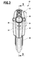
- an inventive handpiece 10 is shown schematically for a Dampfsaug réelle.
- the handpiece 10 has a housing 12, which is formed by a first housing half shell 14 and a second housing half shell 16.
- the two housing half shells 14 and 16 are releasably connected to each other by means of connecting screws. Together they form a hose guide member 18 and a laterally adjoining the hose guide member 18 handle 20. Together, the hose guide part 18 and the handle 20 define a circumferentially closed handle opening 22, which is bounded by an oval-shaped annular wall 24.
- a suction line 26 is passed, which is formed by a rigid suction channel 28 and a subsequent thereto flexible suction hose 30.
- the suction channel 28 protrudes with a tubular inlet section 32 from a front side 34 of the housing 12, and the suction hose 30 is led out of a rear side 36 of the housing 12 facing away from the front side 34.
- At its end facing away from the suction channel 28 of the suction hose 30 carries a known per se and therefore not shown in the drawing first connector part, with the aid of the suction hose can be connected to a dirt container of Dampfsaug réelles.
- the inlet section 32 forms with its free end a suction inlet 38, to which the suction line 26 connects.
- a flexible steam line 42 which, like the suction line 26, passes through the tube guide part 18 of the housing.
- a Dampfmengenregulierventil 44 which is disposed on the front side 34 of the housing 12 below the input portion 32 of the suction channel 28.
- the steam line 42 carries a known per se and therefore not shown in the drawing second connection part, with the aid of the steam line 42 can be connected to a steam generator of Dampfsaug réelles.
- valve housing 46 which protrudes with a front housing portion of the housing 12 and at its free end has a vapor outlet 50.
- the valve housing 46 forms a sleeve which surrounds a through-passage 54, into which a hose nipple 56 projecting laterally from the valve housing 46 opens.
- a hose nipple 56 At the hose nipple 56, the flexible steam line 42 is connected.
- the passageway 54 has a channel constriction in the form of a vapor passage 60, which is arranged downstream of the hose nipple 56.
- a valve body 62 dives with a plunger 64 a. In a closed position of the valve body 62, the plunger 64 discharges the vapor passage 60. Depending on the distance the plunger 64 occupies to the vapor passage 60, a greater or lesser amount of vapor per unit time may flow through the vapor passage 60.
- the valve body 62 has at the end facing away from the vapor passage 60 of the plunger 64 a U-shaped pin holder 66 which carries on its outer sides two aligned mutually aligned coupling pins 68, 70.
- the two coupling pins 68, 70 each dive between two prongs of a coupling fork 72 and 74, which receive the valve body 62 between them and integrally with a configured as a pivoting lever 76 Coupling member are connected.
- the pivot lever 76 is annular and closed in itself. It surrounds the suction channel 28 in the circumferential direction. It is formed by a first longitudinal strut 78 and a second longitudinal strut 80, which are integrally and rigidly connected to one another via a first transverse strut 82 and a second transverse strut 84.
- the first transverse strut 82 is arranged on the upper side 86 of the suction line 26 facing away from the steam quantity regulating valve 44, and the second transverse strut 84 is arranged on the underside 40 of the suction line 26 facing the steam quantity regulating valve 44.
- the second transverse strut 84 is integrally connected to the two coupling forks 72, 74.
- the two longitudinal struts 78, 80 carry on their opposite outer sides in each case a bearing pin 88, 90.
- the two bearing pins 88, 90 are aligned with each other and each pivotably mounted on a housing half shell 14 and 16 respectively.
- the bearing pins 88, 90 define a first pivot axis 92 about which the pivot lever 76 is pivotally mounted to the housing half shells 14, 16.
- the two longitudinal struts 78, 80 carry in the area between the bearing pins 88, 90 and the first cross member 82 facing each other in each case a guide pin 94.
- the guide pins 94 each dive into a guide track of a trained like a slider first actuating element 98 a.
- the first actuating element 98 protrudes from the housing 12 with a first actuating section 100 on the side of the suction line 26 facing away from the steam quantity regulating valve 44.
- a guide section 102 adjoins the first actuating section 100, said guide section being displaceably guided on the two housing half-shells 14, 16 is and has side walls facing away from each other, in whose opposite outer sides in each case a guide track in the form of a guide groove is formed.
- a guide groove 108 is in FIG. 4 recognizable. In each case a guide pin 94 of the pivot lever 76 dips into the guide grooves.
- the first actuator 98 can be moved by the user.
- a sliding movement of the first actuating element 98 results in a pivoting movement of the pivoting lever 76, which in turn results in a displacement movement of the valve body 62 relative to the valve housing 46 of the steam quantity regulating valve 44.
- a larger or smaller amount of steam per unit of time can thus flow through the vapor passage 60.
- the guide grooves 108 form a guide slot, in which the guide pins 94 are guided displaceably.
- the two housing switches 14, 16 receive an electrical switching element in the form of a microswitch 110 which has a switch plunger 112 and is electrically connected to a steam supply member of the Dampfsauguzes about only partially shown in the drawing electrical lines 114, 116.
- the steam supply member may be formed for example in the form of a solenoid valve or for example in the form of a water heater or an electrically heatable boiler.
- the microswitch 110 is coupled to a second actuating element of the handpiece 10 designed as an actuating lever 118.
- the actuating lever 118 is pivotally mounted about a second pivot axis 120 in the region of the handle 20 between the two housing half-shells 14, 16.
- the second pivot axis 120 is aligned parallel to the first pivot axis 92 about which the pivot lever 76 is pivotable.
- the actuating lever 118 has a second actuating portion 122 which engages through a wall opening 124 of the annular wall 24 surrounding the handle opening 22 and thus projects into the handle opening 22.
- the second actuating portion 122 On its side facing away from the handle opening 22, the second actuating portion 122 carries a switching cam 126, which interacts with the switch plunger 112 of the microswitch 110.
- a compression spring 128 By means of a compression spring 128, the actuating lever 118 is biased into a first pivotal position in which the switching cam 126 releases the switch plunger 112.
- the user can pivot the operating lever 118 against the spring force of the compression spring 128 about the second pivot axis 120 such that the control cam 126 actuates the switch tappet 112 and thereby transmits an electrical signal to the steam providing member, such as a solenoid valve, of the steam suction apparatus from the microswitch 110 steam for the handpiece 10.
- the steam providing member such as a solenoid valve
- the actuating lever 118 can be locked in its first pivot position shown in the drawing.
- the handpiece 10 on a locking member which is formed in the illustrated embodiment as an extension 130, which is the microswitch 110 facing formed on the first actuating element 98.
- the extension 130 and the first actuating element 98 together form a one-piece plastic molded part. Takes the first actuator 98 its position shown in the drawing, so is the extension 130 with its the first actuator 98 facing away from the end of the actuating lever 118, so that it can not be pivoted by the user.
- a pivoting movement of the actuating lever 118 is only possible when the user moves the first actuating element 98 in the direction of the suction channel 28 to the front.
- the user can pivot the operating lever 118 so that, due to the electrical signal provided by the microswitch 110, steam may be supplied to the handpiece 10 via the steam line which may be directed to a surface to be cleaned via the steam passage 60 and the steam outlet 50 ,
- a known per se and therefore not shown in the drawing suction nozzle can be connected, wherein the suction channel 28 is immersed in a connection part of the suction nozzle.
- a catch element 134 which is prestressed by means of a detent spring 132 into a detent position, is held on the suction channel 28, which is integrally connected to a release button 136.
- the release button 136 protrudes as well as a latching projection 138 of the locking element 134 from the suction channel 28 on the steam flow regulating valve 44 facing away from the top.
- the locking projection 38 engages in a complementary configured recess of the suction nozzle, so that the suction nozzle is mechanically held on the handpiece 10. If the suction nozzle from the handpiece 10 are released again, the user can do this the release button 136 actuate, so that the locking projection 138 in a release position is moved, in which it releases the complementary formed locking receptacle of the suction nozzle.
- the handpiece 10 has a very compact design, wherein the user has the opportunity to regulate the amount of steam deliverable per unit time directly on the handpiece 10 by moving the first actuator 98 in a desired position.
- the first actuating element 98 is arranged on the upper side of the housing 12 facing away from the steam quantity regulating valve 40 and mechanically coupled to the steam quantity regulating valve 44 via the pivot lever 76.
- the pivot lever 76 is configured mechanically very strong, in which it forms a closed ring shape and the suction line 26 completely surrounds in the circumferential direction in the region of the suction channel 28.
- the user can embrace the handle 20, whereby he can reach through the handle opening 22 with his fingers.
- the provision of steam for the handpiece 10 may be controlled by the user by means of the actuating lever 118. Since the handle opening 22 is surrounded in the circumferential direction of the annular wall 24, there is no danger to the user in handling the handpiece 10 that he comes into contact with the steam line 42 and the Dampfmengenregulierventil 44 in contact. The handling of the handpiece 10 is thus very comfortable for the user.
Landscapes
- Massaging Devices (AREA)
- Dental Tools And Instruments Or Auxiliary Dental Instruments (AREA)
- Surgical Instruments (AREA)
Applications Claiming Priority (1)
| Application Number | Priority Date | Filing Date | Title |
|---|---|---|---|
| DE102012110844.7A DE102012110844A1 (de) | 2012-11-12 | 2012-11-12 | Handstück für ein Dampfsauggerät |
Publications (2)
| Publication Number | Publication Date |
|---|---|
| EP2730207A2 true EP2730207A2 (fr) | 2014-05-14 |
| EP2730207A3 EP2730207A3 (fr) | 2018-01-10 |
Family
ID=49518838
Family Applications (1)
| Application Number | Title | Priority Date | Filing Date |
|---|---|---|---|
| EP13191766.8A Withdrawn EP2730207A3 (fr) | 2012-11-12 | 2013-11-06 | Pièce à main pour un appareil d'aspiration de vapeur |
Country Status (2)
| Country | Link |
|---|---|
| EP (1) | EP2730207A3 (fr) |
| DE (1) | DE102012110844A1 (fr) |
Families Citing this family (4)
| Publication number | Priority date | Publication date | Assignee | Title |
|---|---|---|---|---|
| DE102017100567B4 (de) | 2017-01-12 | 2024-05-08 | Engelbert Gmeilbauer | System zum Ausbringen eines Gemisches |
| DE102019100640B4 (de) | 2018-01-12 | 2023-04-27 | Engelbert Gmeilbauer | System zum Ausbringen eines Gemisches mit Justiereinrichtung und Aktivierungsbereichen |
| DE202021004297U1 (de) | 2021-04-06 | 2023-08-22 | Engelbert Gmeilbauer | Vorrichtung zum Ausbringen einer Druckluft-Fluid-Mischung, umfassend einen Anschlusskörper |
| DE102021001742A1 (de) | 2021-04-06 | 2022-10-06 | Engelbert Gmeilbauer | Vorrichtung zum Ausbringen einer Druckluft-Fluid-Mischung, umfassend einen Anschlusskörper |
Citations (1)
| Publication number | Priority date | Publication date | Assignee | Title |
|---|---|---|---|---|
| WO2004073478A1 (fr) | 2003-02-19 | 2004-09-02 | Polti S.P.A. | Poignee pour buse d'un appareil de nettoyage electromenager |
Family Cites Families (7)
| Publication number | Priority date | Publication date | Assignee | Title |
|---|---|---|---|---|
| GB1520761A (en) * | 1975-07-23 | 1978-08-09 | Steam Vacuum Extraction Ltd | Hand tools for use with steam and vacuum cleaning apparatus |
| US4083077A (en) * | 1975-12-15 | 1978-04-11 | Knight Arlen M | Hand tool for cleaning fabric |
| US5459901A (en) * | 1994-01-14 | 1995-10-24 | Bissell Inc. | Hose and wand assembly for water extraction machine |
| CH690396A5 (de) * | 1994-10-17 | 2000-08-31 | Thomas Robert Metall Elektro | Staubsauger. |
| US6571421B1 (en) * | 2000-10-03 | 2003-06-03 | John Chun Kuen Sham | Vacuum cleaner and steamer apparatus |
| DE10313396B4 (de) * | 2002-03-26 | 2007-06-14 | Falch Hochdruckstrahlsysteme Gmbh | Hochdruckreinigungsgerät für im wesentlichen ebene Flächen |
| ITUD20020241A1 (it) * | 2002-11-18 | 2004-05-19 | De Longhi Spa | Dispositivo per la regolazione dell'erogazione del vapore |
-
2012
- 2012-11-12 DE DE102012110844.7A patent/DE102012110844A1/de not_active Withdrawn
-
2013
- 2013-11-06 EP EP13191766.8A patent/EP2730207A3/fr not_active Withdrawn
Patent Citations (1)
| Publication number | Priority date | Publication date | Assignee | Title |
|---|---|---|---|---|
| WO2004073478A1 (fr) | 2003-02-19 | 2004-09-02 | Polti S.P.A. | Poignee pour buse d'un appareil de nettoyage electromenager |
Also Published As
| Publication number | Publication date |
|---|---|
| EP2730207A3 (fr) | 2018-01-10 |
| DE102012110844A1 (de) | 2014-05-15 |
Similar Documents
| Publication | Publication Date | Title |
|---|---|---|
| EP0688543B1 (fr) | Dispositif de nettoyage des dents avec une pièce à main | |
| WO2018184659A1 (fr) | Appareil de nettoyage à pression guidé à la main | |
| EP1886613B1 (fr) | Pulvérisateur portable | |
| EP2821555B1 (fr) | Armature d'évacuation d'eau avec guidage flexible de l'évacuation | |
| EP3890891B1 (fr) | Pistolet pulvérisateur de peinture | |
| CH673212A5 (fr) | ||
| EP2730207A2 (fr) | Pièce à main pour un appareil d'aspiration de vapeur | |
| DE10239713A1 (de) | Haarformgerät | |
| DE20003449U1 (de) | Gasfeuerzeug | |
| DE69715752T2 (de) | Sprühdüse für Schläuche | |
| EP3516283B1 (fr) | Raccord pour eau potable avec protection contre la contamination | |
| DE69509348T2 (de) | Reiningungsvorrichtung, insbesondere für Haushaltgebrauch | |
| EP1262240B1 (fr) | Soupape pour une buse de décharge d'eau avec un dispositif de commutation | |
| EP3442716B1 (fr) | Dispositif pour la mise sous pression et la distribution d'un liquide de nettoyage | |
| EP2509722B1 (fr) | Poignée pour nettoyeur à vapeur | |
| EP0229207B1 (fr) | Pièce à main pour douches buccales | |
| WO2016146157A1 (fr) | Pistolet de pulvérisation à des fins d'irrigation | |
| DE69619098T2 (de) | Reinigungsvorrichtung, insbesondere für Haushaltsgebrauch | |
| EP3643843B1 (fr) | Cartouche de commutation pour connecter une voie d'eau dans une armature, une douchette ou une pomme de douche | |
| EP3454993B1 (fr) | Pistolet à soupape pour nettoyeur haute pression | |
| DE3632375A1 (de) | Vorrichtung zum zubereiten von cappuccino | |
| DE102024115546A1 (de) | Spritzpistole für ein hochdruckreinigungsgerät | |
| WO2017194169A9 (fr) | Pistolet à soupape pour nettoyeur haute pression | |
| DE19644979A1 (de) | Medizinisches oder dentales Handstück mit einer Einrichtung zur Abgabe der Medien Luft, Wasser oder einem Spray | |
| DE102013006602B4 (de) | Sanitärbrause mit einem Brausekopf |
Legal Events
| Date | Code | Title | Description |
|---|---|---|---|
| PUAI | Public reference made under article 153(3) epc to a published international application that has entered the european phase |
Free format text: ORIGINAL CODE: 0009012 |
|
| 17P | Request for examination filed |
Effective date: 20131106 |
|
| AK | Designated contracting states |
Kind code of ref document: A2 Designated state(s): AL AT BE BG CH CY CZ DE DK EE ES FI FR GB GR HR HU IE IS IT LI LT LU LV MC MK MT NL NO PL PT RO RS SE SI SK SM TR |
|
| AX | Request for extension of the european patent |
Extension state: BA ME |
|
| PUAL | Search report despatched |
Free format text: ORIGINAL CODE: 0009013 |
|
| AK | Designated contracting states |
Kind code of ref document: A3 Designated state(s): AL AT BE BG CH CY CZ DE DK EE ES FI FR GB GR HR HU IE IS IT LI LT LU LV MC MK MT NL NO PL PT RO RS SE SI SK SM TR |
|
| AX | Request for extension of the european patent |
Extension state: BA ME |
|
| RIC1 | Information provided on ipc code assigned before grant |
Ipc: A47L 11/40 20060101AFI20171204BHEP |
|
| R17P | Request for examination filed (corrected) |
Effective date: 20180709 |
|
| RBV | Designated contracting states (corrected) |
Designated state(s): AL AT BE BG CH CY CZ DE DK EE ES FI FR GB GR HR HU IE IS IT LI LT LU LV MC MK MT NL NO PL PT RO RS SE SI SK SM TR |
|
| RAP1 | Party data changed (applicant data changed or rights of an application transferred) |
Owner name: ALFRED KAERCHER SE & CO. KG |
|
| GRAP | Despatch of communication of intention to grant a patent |
Free format text: ORIGINAL CODE: EPIDOSNIGR1 |
|
| INTG | Intention to grant announced |
Effective date: 20200225 |
|
| STAA | Information on the status of an ep patent application or granted ep patent |
Free format text: STATUS: THE APPLICATION IS DEEMED TO BE WITHDRAWN |
|
| 18D | Application deemed to be withdrawn |
Effective date: 20200707 |