EP2730451A1 - Vorrichtung und Verfahren zur Steuerung einer Induktionsspule - Google Patents
Vorrichtung und Verfahren zur Steuerung einer Induktionsspule Download PDFInfo
- Publication number
- EP2730451A1 EP2730451A1 EP12192417.9A EP12192417A EP2730451A1 EP 2730451 A1 EP2730451 A1 EP 2730451A1 EP 12192417 A EP12192417 A EP 12192417A EP 2730451 A1 EP2730451 A1 EP 2730451A1
- Authority
- EP
- European Patent Office
- Prior art keywords
- induction coil
- efficiency
- set point
- determined
- vehicle
- Prior art date
- Legal status (The legal status is an assumption and is not a legal conclusion. Google has not performed a legal analysis and makes no representation as to the accuracy of the status listed.)
- Withdrawn
Links
Images


Classifications
-
- B—PERFORMING OPERATIONS; TRANSPORTING
- B60—VEHICLES IN GENERAL
- B60L—PROPULSION OF ELECTRICALLY-PROPELLED VEHICLES; SUPPLYING ELECTRIC POWER FOR AUXILIARY EQUIPMENT OF ELECTRICALLY-PROPELLED VEHICLES; ELECTRODYNAMIC BRAKE SYSTEMS FOR VEHICLES IN GENERAL; MAGNETIC SUSPENSION OR LEVITATION FOR VEHICLES; MONITORING OPERATING VARIABLES OF ELECTRICALLY-PROPELLED VEHICLES; ELECTRIC SAFETY DEVICES FOR ELECTRICALLY-PROPELLED VEHICLES
- B60L53/00—Methods of charging batteries, specially adapted for electric vehicles; Charging stations or on-board charging equipment therefor; Exchange of energy storage elements in electric vehicles
- B60L53/10—Methods of charging batteries, specially adapted for electric vehicles; Charging stations or on-board charging equipment therefor; Exchange of energy storage elements in electric vehicles characterised by the energy transfer between the charging station and the vehicle
- B60L53/12—Inductive energy transfer
- B60L53/126—Methods for pairing a vehicle and a charging station, e.g. establishing a one-to-one relation between a wireless power transmitter and a wireless power receiver
-
- B—PERFORMING OPERATIONS; TRANSPORTING
- B60—VEHICLES IN GENERAL
- B60L—PROPULSION OF ELECTRICALLY-PROPELLED VEHICLES; SUPPLYING ELECTRIC POWER FOR AUXILIARY EQUIPMENT OF ELECTRICALLY-PROPELLED VEHICLES; ELECTRODYNAMIC BRAKE SYSTEMS FOR VEHICLES IN GENERAL; MAGNETIC SUSPENSION OR LEVITATION FOR VEHICLES; MONITORING OPERATING VARIABLES OF ELECTRICALLY-PROPELLED VEHICLES; ELECTRIC SAFETY DEVICES FOR ELECTRICALLY-PROPELLED VEHICLES
- B60L53/00—Methods of charging batteries, specially adapted for electric vehicles; Charging stations or on-board charging equipment therefor; Exchange of energy storage elements in electric vehicles
- B60L53/30—Constructional details of charging stations
- B60L53/35—Means for automatic or assisted adjustment of the relative position of charging devices and vehicles
- B60L53/38—Means for automatic or assisted adjustment of the relative position of charging devices and vehicles specially adapted for charging by inductive energy transfer
- B60L53/39—Means for automatic or assisted adjustment of the relative position of charging devices and vehicles specially adapted for charging by inductive energy transfer with position-responsive activation of primary coils
-
- H—ELECTRICITY
- H02—GENERATION; CONVERSION OR DISTRIBUTION OF ELECTRIC POWER
- H02J—ELECTRIC POWER NETWORKS; CIRCUIT ARRANGEMENTS OR SYSTEMS FOR SUPPLYING OR DISTRIBUTING ELECTRIC POWER; SYSTEMS FOR STORING ELECTRIC ENERGY
- H02J50/00—Circuit arrangements or systems for wireless supply or distribution of electric power
- H02J50/10—Circuit arrangements or systems for wireless supply or distribution of electric power using inductive coupling
-
- H—ELECTRICITY
- H02—GENERATION; CONVERSION OR DISTRIBUTION OF ELECTRIC POWER
- H02J—ELECTRIC POWER NETWORKS; CIRCUIT ARRANGEMENTS OR SYSTEMS FOR SUPPLYING OR DISTRIBUTING ELECTRIC POWER; SYSTEMS FOR STORING ELECTRIC ENERGY
- H02J50/00—Circuit arrangements or systems for wireless supply or distribution of electric power
- H02J50/20—Circuit arrangements or systems for wireless supply or distribution of electric power using microwaves or radio frequency waves
-
- H—ELECTRICITY
- H02—GENERATION; CONVERSION OR DISTRIBUTION OF ELECTRIC POWER
- H02J—ELECTRIC POWER NETWORKS; CIRCUIT ARRANGEMENTS OR SYSTEMS FOR SUPPLYING OR DISTRIBUTING ELECTRIC POWER; SYSTEMS FOR STORING ELECTRIC ENERGY
- H02J50/00—Circuit arrangements or systems for wireless supply or distribution of electric power
- H02J50/80—Circuit arrangements or systems for wireless supply or distribution of electric power involving the exchange of data, concerning supply or distribution of electric power, between transmitting devices and receiving devices
-
- Y—GENERAL TAGGING OF NEW TECHNOLOGICAL DEVELOPMENTS; GENERAL TAGGING OF CROSS-SECTIONAL TECHNOLOGIES SPANNING OVER SEVERAL SECTIONS OF THE IPC; TECHNICAL SUBJECTS COVERED BY FORMER USPC CROSS-REFERENCE ART COLLECTIONS [XRACs] AND DIGESTS
- Y02—TECHNOLOGIES OR APPLICATIONS FOR MITIGATION OR ADAPTATION AGAINST CLIMATE CHANGE
- Y02T—CLIMATE CHANGE MITIGATION TECHNOLOGIES RELATED TO TRANSPORTATION
- Y02T10/00—Road transport of goods or passengers
- Y02T10/60—Other road transportation technologies with climate change mitigation effect
- Y02T10/70—Energy storage systems for electromobility, e.g. batteries
-
- Y—GENERAL TAGGING OF NEW TECHNOLOGICAL DEVELOPMENTS; GENERAL TAGGING OF CROSS-SECTIONAL TECHNOLOGIES SPANNING OVER SEVERAL SECTIONS OF THE IPC; TECHNICAL SUBJECTS COVERED BY FORMER USPC CROSS-REFERENCE ART COLLECTIONS [XRACs] AND DIGESTS
- Y02—TECHNOLOGIES OR APPLICATIONS FOR MITIGATION OR ADAPTATION AGAINST CLIMATE CHANGE
- Y02T—CLIMATE CHANGE MITIGATION TECHNOLOGIES RELATED TO TRANSPORTATION
- Y02T10/00—Road transport of goods or passengers
- Y02T10/60—Other road transportation technologies with climate change mitigation effect
- Y02T10/7072—Electromobility specific charging systems or methods for batteries, ultracapacitors, supercapacitors or double-layer capacitors
-
- Y—GENERAL TAGGING OF NEW TECHNOLOGICAL DEVELOPMENTS; GENERAL TAGGING OF CROSS-SECTIONAL TECHNOLOGIES SPANNING OVER SEVERAL SECTIONS OF THE IPC; TECHNICAL SUBJECTS COVERED BY FORMER USPC CROSS-REFERENCE ART COLLECTIONS [XRACs] AND DIGESTS
- Y02—TECHNOLOGIES OR APPLICATIONS FOR MITIGATION OR ADAPTATION AGAINST CLIMATE CHANGE
- Y02T—CLIMATE CHANGE MITIGATION TECHNOLOGIES RELATED TO TRANSPORTATION
- Y02T90/00—Enabling technologies or technologies with a potential or indirect contribution to GHG emissions mitigation
- Y02T90/10—Technologies relating to charging of electric vehicles
- Y02T90/12—Electric charging stations
-
- Y—GENERAL TAGGING OF NEW TECHNOLOGICAL DEVELOPMENTS; GENERAL TAGGING OF CROSS-SECTIONAL TECHNOLOGIES SPANNING OVER SEVERAL SECTIONS OF THE IPC; TECHNICAL SUBJECTS COVERED BY FORMER USPC CROSS-REFERENCE ART COLLECTIONS [XRACs] AND DIGESTS
- Y02—TECHNOLOGIES OR APPLICATIONS FOR MITIGATION OR ADAPTATION AGAINST CLIMATE CHANGE
- Y02T—CLIMATE CHANGE MITIGATION TECHNOLOGIES RELATED TO TRANSPORTATION
- Y02T90/00—Enabling technologies or technologies with a potential or indirect contribution to GHG emissions mitigation
- Y02T90/10—Technologies relating to charging of electric vehicles
- Y02T90/14—Plug-in electric vehicles
Definitions
- the invention relates to a device and a method for controlling an induction coil.
- Inductive charging systems are one option to recharge electrical vehicles when parked or while moving.
- Inductive charging systems comprise an induction coil as primary coil.
- the primary coil is used to generate an electromagnetic field suitable to penetrate a secondary coil of an electric vehicle when the secondary coil is near the primary coil.
- the best efficiency of the charging is achieved when the alignment between the primary coil and the secondary coil is optimal for energy transfer.
- This alignment is for example achieved by parking the electrical vehicle so that the secondary coil overlaps with the primary coil.
- In charging systems for moving vehicles multiple primary coils are typically mounted on a lane of a road one after another with a certain distance in-between the primary coils. In such systems it is important to predict the alignment of the secondary coil of the moving vehicle and the primary coils for optimal energy transfer.
- the object of the invention is thus to provide improved control for induction coils in charging systems for movable vehicles.
- the main idea of the invention is to control an induction coil by determining from information about the power transfer of a first induction coil a set point for a second induction coil.
- a first set point for the switching time for operating a first induction coil in a first pre-determined operating mode is determined, and a second set point for the switching time for operating a second induction coil in a second pre-determined operating mode is determined.
- the offset is determined depending on the first set point and an offset.
- the offset is determined depending on the difference between the first set point and a reference time. This increases the accuracy of the offset.
- the offset is determined from information about a third induction coil, in particular the efficiency of the power transfer between the first induction coil and the third induction coil. This way the offset is determined specifically for the secondary coil of the vehicle moving across the lane of the road.
- the reference time is determined depending on the information about the efficiency.
- the efficiency is easily measurable and can be used to look up the reference time in a characteristic curve of the inductive charging system.
- the first set point is determined from information for the speed at which the third induction coil is moving relative to the first induction coil. This gives a good estimate for the first set point without knowledge about the offset yet.
- the first set point is determined from information about the distance between the third induction coil and the first induction coil. This further improves the estimation.
- the offset is determined depending on a first pair of values indicative of a first efficiency and a first reference time for switching into a first pre-determined operating mode. Using the first pair of values simplifies the calculation and improves the processing speed.
- the offset is determined depending on a second pair of values indicative of a second efficiency and a second reference time for switching out of the first pre-determined operating mode. This improves the robustness of the calculation because the offset can be determined not only when switching into the first pre-determined operating mode but also when switching out of the first pre-determined operating mode.
- the switching of the first induction coil according to the first set point is triggered.
- the switching of the second induction coil according to second set point is triggered. This way, the outputs necessary to control the induction coil is generated.
- two first set points or two second set points are determined. This way the set points for switching into the first operating mode and out of the first operating mode and for switching into the second operating mode and for switching out of the second operating mode are calculated respectively.
- one of the two first or second set points indicates a switch-on time and the other indicates a switch-off time.
- switch-on and -off times simplifies the calculation and the processing time.
- Figure 1 shows part of an inductive charging system 100.
- the inductive charging system 100 comprises as primary coils, a first induction coil 101 and a second induction coil 102.
- the first induction coil 101 and the second induction coil 102 are integrated into the pavement of a road 103 one after another in the driving direction of the lane of the road.
- the mounting position may vary, in particular the coils may be installed over the pavement or at the side of the road. In general the mointing position is such that an electromagnetic field generated by the primary coils penetrates an area above the pavement.
- Further inductive coils may be mounted consecutively in the road 103 as part of the inductive charging system and are not depicted in Figure 1 ,
- the inductive charging system 100 furthermore comprises a device 104 for controlling an induction coil.
- the device 104 is connected to the first induction coil 101 and the second induction coil 102 respectively.
- the device 104 may be connected to any consecutive induction coil as well.
- Several devices 104 may be used along to road 103 to control the induction coils separately as well.
- the inductive charging system 100 furthermore comprises according to the example an antenna 105.
- the antenna 105 is connected to the device 104. Furthermore the antenna 105 is mounted near the road 103 for example integrated into the pavement of the road 103 near the surface of the road 103. The antenna 105 may be mounted next to the road 103 as well.
- Figure 1 depicts a vehicle 110 having a third induction coil 111 and a transceiver 112.
- the third induction coil 111 and the transceiver 112 are mounted near the underbody of the vehicle 110 facing downwards towards the road 103 when the vehicle 110 is driving on the road 103.
- the mounting position of the first induction coil 101 and the second induction coil 102 as well as the third induction coil 111 is selected so that an preferably alternating electromagnetic field generated by the first induction coil 101 or the second induction coil 102 penetrates the third induction coil 111 when the vehicle 110 is driving on the road 103 over or near the mounting position of the first induction coil 101 or the second induction coil 102 respectively.
- the mounting position of the antenna 105 and the transceiver 112 is selected so that signals can be transmitted between the two.
- a signal sent by the antenna 105 is receivable by the transceiver 112 when the vehicle 110 is driving on the road 103 over or near the mounting position of the antenna 105.
- the transceiver 112 is adapted to emit a signal receivable by the antenna 105.
- the transceiver 112 is adapted to send an identification of the vehicle 110 and additional information upon receipt of a request from the antenna 105.
- the additional information includes for example information about the third induction coil 111 and information about the power transferred to the third induction coil 111.
- the information about the third induction coil 111 is for example its resistance.
- the information about the power transferred to the third induction coil 111 is for example the electrical current flowing through the third induction coil 111 as value in Ampere. Alternatively the power transferred in Watt may be used.
- the additional information comprises information about the speed of the vehicle 110.
- the data link between the transceiver 112 and the antenna 105 is in this example a wireless link, e.g. according to the Bluetooth or IEEE 802.11 standard. In this case the antenna 105 is adapted to communicate according to the suitable standard with the transceiver 112.
- the transceiver 112 comprises an active wireless transmitter and a radio frequency identification tag including the identification of the vehicle 110 mounted to the vehicle 110.
- the radio frequency identification tag may be active or passive.
- the active wireless transmitter is adapted to use aforementioned wireless link to transmit the additonal information.
- the antenna 105 comprises a first circuitry adapted to send radio frequency signals suitable to trigger a response including the identification of the vehicle 110 from the radio frequency identification tag. This signal for example triggers the tag to return the information about the vehicle 110 stored in the transceiver 112, e.g. via the oscillating circuit of the radio frequency identification tag.
- the active wireless transmitter of the transceiver 112 is in this example used to send the additional information.
- the information about the power transferred or the speed of the vehicle 110 may be sent.
- This additional information is for example determined in the vehicle 110 by the inductive charging system and the engine controller respectively.
- the transceiver 112 may be connectable to a data bus of the vehicle 110 for receiving the respective information.
- the additional information may be determined by the transceiver 112 and returned in the response.
- the antenna 105 is for example adapted to send out the signal to request the response at pre-determined time intervals, for example every 10 th millisecond. Furthermore, the antenna 105 is adapted to send any response received from the transceiver 112 to the device 104 via a data link between the two.
- the distance between the antenna 105 and the first induction coil 101 is labelled "s" in figure 1 .
- the distance between the first induction coil 101 and the second induction coil 102 is labelled "d" in figure 1 .
- the length of the first induction coil 101 and the second induction coil 102 are labelled "1".
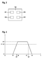
- Figure 2 depicts the device 104 for controlling the induction coil.
- the device 104 comprises a processor 201 adapted to determine a first set point ts1 for the switching time for operating the first induction coil 101 in a first pre-determined operating mode and adapted to determine a second set point ts2 for the switching time for operating the second electric coil 102 in a second pre-determined operating mode, wherein the second set point ts2 is determined depending an offset x.
- the second set point ts2 may be determined depending on the first set point ts1.
- the device 104 comprises an actuator 202 adapted to trigger switching of the first induction coil 101 according to the first set point ts1 or to trigger the switching of the second induction coil 102 according to the second set point ts2.
- the device 104 comprises an input 203 to trigger the sending of the signal by the antenna 105 and receive information about the third induction coil 111.
- the input 203 is connectable to the antenna 105 via aforementioned data link.
- the antenna 105 may be integrated into the device 104 as part of the input 203.
- the input 203 is adapted to receive the information about the identification of the vehicle 110 and the additional information from the transceiver 112 via the antenna 105.
- the input 203 is adapted to trigger the sending of the radio frequency every 10 th millisecond.
- the input 203 is adapted to upon receipt of the response including the identification of the vehicle 110, trigger the request for additional information via the wireless link.
- the information about the identification of the vehicle 110 is received as the radio frequency identification information from the radio frequency identification device and the additional information, e.g. the information about the power transfer to the third induction coil 111 or the speed of the vehicle 110 is received via the wireless link.
- both requests are sent simultaneously or as a single request.
- the input 203 is adapted to determine information about the power transfer between the first induction coil 101 to the third induction coil 111.
- the input 203 is adapted to determine a measured efficiency ⁇ x of the power transfer from the received additional information and information about the first induction coil 101.
- the receive information about the power transferred is used.
- the measured efficiency ⁇ x is for example calculated from the received transferred power as ratio between the power used to generate the electromagnetic field in the first induction coil 101 and the currently transferred power.
- the currently transferred power is determined from that information and the ratio is calculated.
- the input 203 may be adapted to receive information that allows to look up the information about the third induction coil 111 in storage 204, e.g. in a database.
- the identifier of the vehicle 110 stored in the transceiver 112 e.g. the radio frequency identification of the radio frequency identification tag
- the information about the third induction coil 111 may be stored in the storage 204 assigned to the identification.
- the storage 204 may be internal to the device 104 as depicted in figure 2 or external. In the latter case an additional data link not depicted in figure 2 may be used by the input 203 to access the storage.
- the information is for example stored in an initialization when manufacturing the device 104 or stored as update by an administrator at any time.
- the storage 204 is adapted according to the example to store an efficiency characteristic for the inductive charging system 100 as well.
- the efficiency characteristic is explained making reference to figure 3 and 4 .
- Figure 3 depicts an exemplary efficiency characteristic for the power transfer between the first induction coil 101 and the third induction coil 103 over time.
- the efficiency characteristic is a characteristic curve. Any other form of storing this information, e.g. as array, may be used as well.
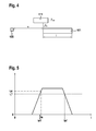
- Figure 4 depicts the position of the third induction coil 111 relative to the first induction coil 101.
- the direction of travel on the lane of the road 103 in which the first induction coil 101 is installed is depicted in figure 4 as arrow. It is assumed that the vehicle 110 and hence the third induction coil 111 moves in the travel direction with a speed v.
- the efficiency of the power transfer changes depending on the relative position of the first induction coil 101 and the third induction coil 103. Referencing Figure 3 , the efficiency is 0 while the third induction coil 111 does not overlap with the first induction coil 101. This is due to the fact that the electromagnetic field generated by the first induction coil 101 does not penetrate the third induction coil 111 in that case.
- the distance between the third induction coil 111 and the first induction coil 101 is equal to the distance s between the antenna 105 and the first induction coil 101.
- the efficiency stays at 0 until the third induction coil 111 starts to overlap with the first induction coil 101.
- the time the overlap starts is labelled t1 in Figure 3 .
- the efficiency of the power transfer increases as depicted in figure 3 until a maximum efficiency ⁇ m is reached. According to the example the maximum efficiency ⁇ m is reached when the third induction coil 111 is above the first induction coil 101 entirely.
- the corresponding time is labelled t2 in figure 3 .
- the efficiency remains at the maximum efficiency ⁇ 2 as depicted in figure 3 while the third induction coil 111 remains entirely above the area of the first induction coil 101.
- the efficiency starts to drop from the maximum efficiency ⁇ m down to 0.
- the corresponding time is labelled t3 in figure 3 .
- the efficiency is 0 as soon as the third induction coil 111 entirely left the area of above the first induction coil 101.
- the corresponding time is labelled t4 in figure 3 . According to the example the increase to and the reduction from the maximum efficiency ⁇ m is linear.
- the shape of the efficiency characteristic according to figure 3 may vary depending on the first induction coil 101 or the third induction coil 111 or their respective mounting positions. In particular, non-linear shapes may be used in order to describe the efficiency characteristic.
- the efficiency characteristic is for example measured in a calibration by measuring the power transferred from the first induction coil 101 to the third induction coil 111 while the third induction coil 111 is moving with constant speed v across the area above the first induction coil 101.
- constant speed v may be measured and stored for different constant speeds v as well.
- Figure 3 depicts a first pair of values indicative of first efficiency ⁇ 1 and a first reference time te1 for switching into the first pre-determined operating mode.
- figure 3 depicts a second pair of values indicative of a second efficiency ⁇ 2 and a second reference time ta1 for switching out of the first pre-determined operating mode.
- the first efficiency ⁇ 1 and the second efficiency ⁇ 2 are selected as 80 % of the the minimum efficiency needed or the optimal efficiency.
- the optimal efficiency is for example defined as a lossless power transfer between the first induction coil 101 and the third induction coil 111.
- the minimum efficiency needed is for example defined as a value less than the optimal efficiency but sufficient to transfer the energy inductively.
- the first reference time te1 is the time at which the efficiency reaches the first efficiency ⁇ 1 when the third induction coil 111 is moving into the area of the first induction coil 101.
- the second reference time ta1 indicates the point in time at which the efficiency drops down to or below the second efficiency ⁇ 2 when the third induction coil 111 leaves the area above the first induction coil 101.
- the first reference time corresponds to the situation depicted in figure 4 where the third induction coil 111 overlaps with the first induction coil 101 by an area characterised by the distance b that the third induction coil 111 already entered into the area above the first induction coil 101 in travel direction.
- the second reference time ta2 corresponds to the situation where the third induction coil 111 left the area above the first induction coil 101 except for the distance b.
- the third induction coil 111 has the dimensions 1x1m.
- the first efficiency ⁇ 1 and the second efficiency ⁇ 2 are measured in the calibration as 80 % efficiency corresponding to an overlap by 1/3 of the area of the third induction coil 111. This means, that b equals 1/3 of a meter.
- the efficiency characteristic as depicted in figure 3 is, for example, stored in the storage 204 of the device 104.
- the distance s between the antenna 105 and the first induction coil 101 as well as the dimensions of the first induction coil 101, in particular the length 1, and the dimensions of the third induction coil 111, or the distance b, is stored in the storage 204.
- the transceiver 112 may be adapted to provide the dimensions of the third induction coil 111 or the distance b to the device 104 via the antenna 105 upon request.
- the information about the third induction coil 111 and the first induction coil 101 may be determined in the calibration.
- the processor 201 is adapted to determine the first set point ts1 for the switching time for operating the first induction coil 101 in the first pre-determined operating mode.
- the vehicle speed v is for example determined by measurement or received from the transceiver 112 via the antenna 105.
- the antenna 105 may comprise a sensor to determine the speed of the vehicle 110 while it is moving over the area of the antenna 105.
- the transceiver 112 may comprise an interface to provide the information from the vehicle's speedometer.
- the first pre-determined operating mode is the mode in which the first induction coil 101 generates an electromagnetic field suitable to charge the vehicle 110 via the third induction coil 111. It is assumed that the first induction coil 101 is not generating this electromagnetic field while it is not in the first pre-determined operating mode.
- the actuator 202 is adapted to trigger switching of the first induction coil 101 according to aforementioned two first set points ts1, ts2. For example, the actuator 202 switches the first induction coil 101 into the first pre-determined operating mode when the time that the vehicle 110 travelled since it passed the first antenna 105 reaches the time equal to the first set point ts1. This means that the electromagnetic field is switched on by the device 104 when the vehicle 110 is approximately at the position where the third induction coil 111 overlaps by a third with the first induction coil 101.
- the dimensions of the first induction coil 101 are 1x1 m and that the dimensions of the third induction coil 111 are 1x1 m.
- the offset x 6 ms. This means that the vehicle 110 actually travelled at a speed faster than the speed v measured at the position of the antenna 105.
- the characteristic that is closest to the determined vehicle speed v is selected to determine the reference times and the offset.
- This offset x means that using the first set points ts1, ts2 as calculated above for switching into and out of the first pre-determined operating mode of the first induction coil 101 results in a less efficient power transfer and more radiation in the environment, because the first induction coil 101 is switched on and off too late for the minimum alignment needed or the optimal alignment of the induction coils.
- a second pre-determined operating mode is the mode in which the second induction coil 102 generates an electromagnetic field suitable to charge the vehicle 110 via the third induction coil 111. It is assumed that the second induction coil 102 is not generating this electromagnetic field while it is not in the second pre-determined operating mode.
- the processor 201 is adapted to determine the second set point for the switching time for operating the second induction coil 102 in the second pre-determined operating mode depending on the offset x.
- both set points are calculated by the processor 201 depending on the first set point and an offset.
- the dependence on the first set point is included in the aforementioned formula by the term (s+b)/v.
- the processor 201 may be adapted to store the first set point ts1, ts2 after the first calculation and reuse the value to determine the second set point te2, ta2.
- the offset x is calculated for the second induction coil 102 and for any other number of induction coils subsequently following on the road 103.
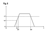
- Figure 6 depicts the situation when the measured efficiency ⁇ x is less than the first efficiency ⁇ 1. According to figure 6 , the same efficiency characteristic as depicted in figure 3 and 5 is used. According to figure 6 , the measured efficiency ⁇ x corresponds to an actual switching time tx earlier than the first reference time te1.
- the processor 201 may be adapted to determine the first set point, i.e. the term (s+b)/v and store it for later use. In both cases, the second set point is determined depending on the offset or the first set point and the offset.
- the offset x is determined from information about the third induction coil 111 in particular the efficiency of the power transfer between the first induction coil 101 and the third induction coil 111.
- the offset x is determined depending on the first pair of values indicative of the first efficiency ⁇ 1 and the first reference time te1 for switching into the first pre-determined operating mode. Likewise, this means that the offset x is determined depending on the second pair of values indicative of the second efficiency ⁇ 2 and the second reference time ta1 for switching out of the first pre-determined operating mode.
- the second efficiency ⁇ 2 is the same as the first efficiency ⁇ 1. This is due to the symmetric shape of the energy transfer efficiency characteristic. However, depending on the induction coils used, this second efficiency ⁇ 2 may be different from the first efficiency ⁇ 1.
- a method for controlling an induction coil is described below making reference to figure 7 .
- the method starts, for example, when at the antenna 105 an approaching vehicle 110 is detected.
- the detection may be based on hand shake for a connection between the input 203 via the antenna 105 and the transceiver 112.
- the speed v of the vehicle 110 may be measured.
- the speed is for example measured by a radar speed sensor integrated into the antenna 105.
- the time counter once started is configured for example to measure the real time, e.g. in milliseconds. Any other timer may be used, e.g. a cycle time of the processor 201.
- a step 701 is executed.
- step 701 information, e.g. about the identification of the vehicle 110 and the additional information is requested from the vehicle 110.
- some information about the third charging coil 110 may be requested from the data base.
- the identification of the vehicle 110 is requested from the radio frequency identification tag.
- the antenna 105 sends a radio frequency identification signal to the radio frequency identification tag on the vehicle 110 requesting the radio frequency identification from the tag.
- the additional information is for example requested via the wireless link according to IEEE 802.11 standard from the transmitter.
- the transceiver 112 upon request signal via the antenna 105 provides the information about the vehicle 110 and the additional information about the vehicle 110.
- the information about the third induction coil 111, the transferred power and the speed v of the vehicle 110 are thus provided.
- a step 702 is executed.
- step 702 a test is performed to determine whether to charge the vehicle 110 or not. For example the charging and billing has to be completed successfully or the identification of the vehicle 110 has to be found in the database. In case charging is allowed, a step 703 is executed, otherwise the method ends.
- Charging and billing may include an optional step of sending charging and billing information, in particular the radio frequency identification received from the vehicle 110 to a charging and billing server. The charging and billing is optional and may be omitted.
- the distance s between the antenna 105 and the first induction coil 101 the distance d between the first induction coil 101 and the second induction coil 102 the length 1 are determined, e.g. read from storage. Furthermore, the distance b and the vehicle speed v are determined. The distance b may be looked up in storage using the identification of the vehicle 110. The vehicle speed v is for example determined from the measurement performed at the position of the antenna 105. Alternatively the vehicle speed v and optionally also the distance b are determined from the information received from the transceiver 112 of the vehicle 111 in step 701. Any of the parameters may also be read from storage 204.
- step 704 is executed.
- step 705 a test is performed whether the time counter t reached the first set point ts1. In case the time counter reached that value, a step 706 is executed. Otherwise, step 705 is executed.
- step 706 the first induction coil 101 is switched to the first pre-determined operating mode, e.g. in which the first induction coil 101 generates the electromagnetic field. Afterwards a step 707 is executed.
- step 707 the measured efficiency ⁇ x and the actual switching time tx are determined.
- the efficiency ⁇ x is calculated from the measured power flow between the first induction coil 101 and the third induction coil 111.
- the actual switching time tx is determined as the time corresponding to the efficiency ⁇ x that was measured in the efficiency characteristic.
- a step 708 is executed.
- step 708 a test is performed to determine whether the measured efficiency ⁇ x is smaller than the maximum efficiency ⁇ m: In case the measured efficiency ⁇ x is smaller than the maximum efficiency ⁇ m a step 709 is executed. Otherwise a step 710 is executed.
- the offset x is determined.
- step 709 is executed and the offset x is calculated as described above.
- This example means that the measured efficiency ⁇ x indicated that the first induction coil 101 was triggered to generate the electromagnetic field too late because when the first induction coil 101 started generating the electromagnetic field, the efficiency already was higher than the minimum efficiency value needed or the optimal efficiency value for starting the energy transfer indicated by the pair of values indicating the first efficiency ⁇ 1 and the first reference time te1. This means that an earlier switching time would provide for better efficiency.
- step 709 is executed and the offset x is calculated as described above.
- the measured efficiency ⁇ x is smaller than the pair of values indicating the first efficiency ⁇ 1 and the first reference time tea1. This indicates that the first induction coil 101 was switched on too early resulting in less than needed or less than optimal efficiency.
- step 713 is executed.
- step 713 a test is performed to determine whether the time counter t reached the other first set point ts2 for switching the first induction coil 101 out of the first pre-determined operating mode, e.g. to switch off the generation of the electromagnetic field in the first induction coil 101.
- the test is performed using the other first set point ts2.
- a step 714 is executed. Otherwise, the step 713 is executed.
- step 714 the first induction coil 101 is triggered to switch out of the first pre-determined operating mode, e.g. to switch off the generation of an electromagnetic field. Afterwards, a step 715 is executed.
- step 710 the measured efficiency ⁇ x and the actual switching time tx are determined as described in step 707. Afterwards, a step 711 is executed.
- step 711 a test is performed to determine if the measured efficiency ⁇ x is smaller or equal to the second efficiency ⁇ 2. In case the measured efficiency ⁇ x is smaller or equal to the second efficiency ⁇ 2, a step 712 is executed. Otherwise the step 710 is executed. This considers the case in which the measured efficiency ⁇ x already has reached the maximum value ⁇ m when switching the first induction coil 101 into the first pre-determined operating mode. In this case to determine the offset x the measured efficiency ⁇ x has to reach the second efficiency ⁇ 2 when the vehicle 160 leaves the area above the first induction coil 101.
- the delay of switching on the first induction coil 101 was so large that the measured efficiency ⁇ x is already in the saturation depicted as flat line of ⁇ m in the efficiency characteristic in the figures 3 , 5 or 6 . Furthermore, this means that the corresponding offset x cannot be determined because the measured efficiency ⁇ x corresponds to multiple actual switching times tx and hence in a single measurement the displacement between the reference times te1 or ta1 and the actual switching time tx is arbitrary. Waiting for the efficiency to drop allows to determine the correct offset x from the falling flank of the efficiency characteristic.
- step 713 is executed.
- the second set point for switching the second induction coil 102 into the second operating mode is determined.
- a step 716 is executed.
- step 716 the other second set point for switching the second induction coil 102 out of the second operating mode is determined.
- a step 717 is executed.
- step 717 the second set points te2, ta2 are used to trigger switching the second induction coil 102 into and out of the second operating mode as described above.
- the steps of the methods described above may vary in order and may not be executed all every time the method is used. Furthermore, the method may not end after step 717 but rather the method may be repeated to determine the set points for the consecutive primary coils in the road 103 until the vehicle 110 passed all of the primary coils in the road 103.
- one antenna 105 is used. Rather than that, several antennas 105 may be used, one or more for an individual first induction coil 101 or second induction coil 102. Likewise several more induction coils maybe used with a single antenna 105. The principles of the method described above remain the same. The offsets and set points may be calculated from the vehicle speed measured at the time the vehicle 110 passes any of the antennas then as well.
- any functional blocks labeled as 'processors' may be provided through the use of dedicated hardware as well as hardware capable of executing software in association with appropriate software.
- the functions may be provided by a single dedicated processor, by a single shared processor, or by a plurality of individual processors, some of which may be shared.
- DSP digital signal processor
- ASIC application specific integrated circuit
- FPGA field programmable gate array
- ROM read only memory
- RAM random access memory
- any switches shown in the figures are conceptual only. Their function may be carried out through the operation of program logic, through dedicated logic, through the interaction of program control and dedicated logic, or even manually, the particular technique being selectable by the implementer as more specifically understood from the context.
- program storage devices e.g., digital data storage media, which are machine or computer readable and encode machine-executable or computer-executable programs of instructions, wherein said instructions perform some or all of the steps of said above-described methods.
- the program storage devices may be, e.g., digital memories, magnetic storage media such as a magnetic disks and magnetic tapes, hard drives, or optically readable digital data storage media.
- the embodiments are also intended to cover computers programmed to perform said steps of the above-described methods.
Landscapes
- Engineering & Computer Science (AREA)
- Power Engineering (AREA)
- Computer Networks & Wireless Communication (AREA)
- Transportation (AREA)
- Mechanical Engineering (AREA)
- Electric Propulsion And Braking For Vehicles (AREA)
- General Induction Heating (AREA)
- Charge And Discharge Circuits For Batteries Or The Like (AREA)
- Current-Collector Devices For Electrically Propelled Vehicles (AREA)
- Near-Field Transmission Systems (AREA)
Priority Applications (6)
| Application Number | Priority Date | Filing Date | Title |
|---|---|---|---|
| EP12192417.9A EP2730451A1 (de) | 2012-11-13 | 2012-11-13 | Vorrichtung und Verfahren zur Steuerung einer Induktionsspule |
| PCT/EP2013/073138 WO2014075968A2 (en) | 2012-11-13 | 2013-11-06 | A device and a method for controlling an induction coil |
| CN201380058972.XA CN104781103A (zh) | 2012-11-13 | 2013-11-06 | 用于控制感应线圈的设备和方法 |
| JP2015541115A JP2016502833A (ja) | 2012-11-13 | 2013-11-06 | 誘導コイルを制御するための装置および方法 |
| US14/432,627 US20150251552A1 (en) | 2012-11-13 | 2013-11-06 | Device and a method for controlling an induction coil |
| KR1020157012284A KR101704320B1 (ko) | 2012-11-13 | 2013-11-06 | 유도 코일을 제어하기 위한 디바이스 및 방법 |
Applications Claiming Priority (1)
| Application Number | Priority Date | Filing Date | Title |
|---|---|---|---|
| EP12192417.9A EP2730451A1 (de) | 2012-11-13 | 2012-11-13 | Vorrichtung und Verfahren zur Steuerung einer Induktionsspule |
Publications (1)
| Publication Number | Publication Date |
|---|---|
| EP2730451A1 true EP2730451A1 (de) | 2014-05-14 |
Family
ID=47177817
Family Applications (1)
| Application Number | Title | Priority Date | Filing Date |
|---|---|---|---|
| EP12192417.9A Withdrawn EP2730451A1 (de) | 2012-11-13 | 2012-11-13 | Vorrichtung und Verfahren zur Steuerung einer Induktionsspule |
Country Status (6)
| Country | Link |
|---|---|
| US (1) | US20150251552A1 (de) |
| EP (1) | EP2730451A1 (de) |
| JP (1) | JP2016502833A (de) |
| KR (1) | KR101704320B1 (de) |
| CN (1) | CN104781103A (de) |
| WO (1) | WO2014075968A2 (de) |
Cited By (2)
| Publication number | Priority date | Publication date | Assignee | Title |
|---|---|---|---|---|
| US20220242255A1 (en) * | 2021-02-02 | 2022-08-04 | Toyota Motor Engineering & Manufacturing North America, Inc. | Systems and methods with dual function coil providing in-vehicle wireless power |
| US20230347771A1 (en) * | 2022-04-27 | 2023-11-02 | Hyundai Motor Company | Vehicle charging system through ess and method and apparatus for managing the same |
Families Citing this family (7)
| Publication number | Priority date | Publication date | Assignee | Title |
|---|---|---|---|---|
| JP5979125B2 (ja) * | 2013-12-11 | 2016-08-24 | トヨタ自動車株式会社 | 非接触送電装置 |
| US10611251B2 (en) * | 2015-11-13 | 2020-04-07 | Nio Usa, Inc. | Distributed processing network for rechargeable electric vehicle tracking and routing |
| US10131238B2 (en) | 2015-11-13 | 2018-11-20 | Nio Usa, Inc. | Charging transmission line under roadway for moving electric vehicle |
| US10160339B2 (en) | 2015-11-13 | 2018-12-25 | Nio Usa, Inc. | Smart grid management |
| US10421368B2 (en) | 2017-04-26 | 2019-09-24 | Witricity Corporation | Static power derating for dynamic charging |
| CN109159679A (zh) * | 2018-08-29 | 2019-01-08 | 广西电网有限责任公司电力科学研究院 | 无线充电汽车多导轨动态充电控制系统及其控制方法 |
| CN109159710A (zh) * | 2018-08-29 | 2019-01-08 | 广西电网有限责任公司电力科学研究院 | 基于车辆定速行驶的动态无线充电系统 |
Citations (3)
| Publication number | Priority date | Publication date | Assignee | Title |
|---|---|---|---|---|
| US20090045773A1 (en) * | 2007-08-13 | 2009-02-19 | Pandya Ravi A | Wireless Charging System for Vehicles |
| KR20110041307A (ko) * | 2009-10-15 | 2011-04-21 | 한국과학기술원 | 세그먼트화된 전기자동차용 급전제어 방법 및 장치 |
| KR20110066822A (ko) * | 2009-12-11 | 2011-06-17 | 한국과학기술원 | 온라인 전기자동차용 세그먼트 충전 제어방법 |
Family Cites Families (13)
| Publication number | Priority date | Publication date | Assignee | Title |
|---|---|---|---|---|
| US5207304A (en) * | 1991-12-03 | 1993-05-04 | The Regents Of The University Of California | Inductive energization system and method for vehicles |
| US6421600B1 (en) * | 1994-05-05 | 2002-07-16 | H. R. Ross Industries, Inc. | Roadway-powered electric vehicle system having automatic guidance and demand-based dispatch features |
| JP2001177916A (ja) | 1999-12-10 | 2001-06-29 | Toyota Motor Corp | エネルギー供給装置 |
| US20060172801A1 (en) * | 2005-01-31 | 2006-08-03 | Saied Hussaini | Video game controller with rechargeable battery system |
| JP2007135335A (ja) | 2005-11-11 | 2007-05-31 | Toyota Motor Corp | エネルギー供給装置、エネルギー供給方法 |
| GB2463693A (en) * | 2008-09-19 | 2010-03-24 | Bombardier Transp Gmbh | A system for transferring electric energy to a vehicle |
| TWI577103B (zh) * | 2010-02-08 | 2017-04-01 | 通路實業集團國際公司 | 置入之寄生金屬檢測及其相關方法 |
| JP5599259B2 (ja) * | 2010-08-09 | 2014-10-01 | マスプロ電工株式会社 | 車両の非接触給電システム |
| MX2013010657A (es) * | 2011-03-21 | 2013-10-07 | Koninkl Philips Nv | Calculo de perdida de energia para transmision de energia inductiva. |
| EP2783891B1 (de) * | 2011-11-25 | 2019-12-25 | Toyota Jidosha Kabushiki Kaisha | Fahrzeug |
| JP5716725B2 (ja) * | 2012-11-21 | 2015-05-13 | トヨタ自動車株式会社 | 送電装置および電力伝送システム |
| JP6291208B2 (ja) * | 2013-10-10 | 2018-03-14 | 株式会社東芝 | 移動体、無線電力伝送システムおよび無線電力伝送方法 |
| JP6515015B2 (ja) * | 2015-11-11 | 2019-05-15 | 株式会社ダイヘン | 非接触電力伝送システム |
-
2012
- 2012-11-13 EP EP12192417.9A patent/EP2730451A1/de not_active Withdrawn
-
2013
- 2013-11-06 JP JP2015541115A patent/JP2016502833A/ja active Pending
- 2013-11-06 WO PCT/EP2013/073138 patent/WO2014075968A2/en not_active Ceased
- 2013-11-06 CN CN201380058972.XA patent/CN104781103A/zh active Pending
- 2013-11-06 US US14/432,627 patent/US20150251552A1/en not_active Abandoned
- 2013-11-06 KR KR1020157012284A patent/KR101704320B1/ko not_active Expired - Fee Related
Patent Citations (3)
| Publication number | Priority date | Publication date | Assignee | Title |
|---|---|---|---|---|
| US20090045773A1 (en) * | 2007-08-13 | 2009-02-19 | Pandya Ravi A | Wireless Charging System for Vehicles |
| KR20110041307A (ko) * | 2009-10-15 | 2011-04-21 | 한국과학기술원 | 세그먼트화된 전기자동차용 급전제어 방법 및 장치 |
| KR20110066822A (ko) * | 2009-12-11 | 2011-06-17 | 한국과학기술원 | 온라인 전기자동차용 세그먼트 충전 제어방법 |
Cited By (4)
| Publication number | Priority date | Publication date | Assignee | Title |
|---|---|---|---|---|
| US20220242255A1 (en) * | 2021-02-02 | 2022-08-04 | Toyota Motor Engineering & Manufacturing North America, Inc. | Systems and methods with dual function coil providing in-vehicle wireless power |
| US11590850B2 (en) * | 2021-02-02 | 2023-02-28 | Toyota Motor Engineering & Manufacturing North America, Inc. | Systems and methods with dual function coil providing in-vehicle wireless power |
| US20230347771A1 (en) * | 2022-04-27 | 2023-11-02 | Hyundai Motor Company | Vehicle charging system through ess and method and apparatus for managing the same |
| US12502996B2 (en) * | 2022-04-27 | 2025-12-23 | Hyundai Motor Company | Vehicle charging system through ESS and method and apparatus for managing the same |
Also Published As
| Publication number | Publication date |
|---|---|
| KR101704320B1 (ko) | 2017-02-07 |
| CN104781103A (zh) | 2015-07-15 |
| WO2014075968A2 (en) | 2014-05-22 |
| US20150251552A1 (en) | 2015-09-10 |
| JP2016502833A (ja) | 2016-01-28 |
| WO2014075968A3 (en) | 2014-07-10 |
| KR20150068465A (ko) | 2015-06-19 |
Similar Documents
| Publication | Publication Date | Title |
|---|---|---|
| EP2730451A1 (de) | Vorrichtung und Verfahren zur Steuerung einer Induktionsspule | |
| KR102406107B1 (ko) | 조절 가능한 플럭스 각도를 갖는 전기 자동차를 위한 무선 충전 시스템 | |
| CN106573545B (zh) | 用于对具有车辆垫的电动车辆无线地充电的装置和方法 | |
| CN107176045B (zh) | 用于车辆的动态感应无线充电系统和车辆的充电系统 | |
| EP2680398B1 (de) | Kontaktfreie stromübertragungsvorrichtung für ein bewegliches teil | |
| US9608465B2 (en) | Devices, systems, and method for power control of dynamic electric vehicle charging systems | |
| US20180111492A1 (en) | Parking alignment sequence for wirelessly charging an electric vehicle | |
| CN108475945B (zh) | 用于检测用于机动车辆的用户设备充电装置的发射区域中的寄生金属对象的装置 | |
| JP2017527246A (ja) | 誘導的充電システムを駆動するための装置及び方法 | |
| CN106255614A (zh) | 用于识别用于车辆的感应充电停放位的方法以及用于多个感应充电停放位的感应充电装置 | |
| JP6391214B2 (ja) | 非接触給電システム | |
| WO2015151467A1 (en) | Power reception device and vehicle including the same | |
| US20230158912A1 (en) | An apparatus for and method of guiding an electric vehicle | |
| US12212151B2 (en) | Contactless power transfer system and method for controlling the same | |
| CN114851868A (zh) | 用偏移传感器向车辆设备传送无线车辆电力的系统和方法 | |
| Sun et al. | Precise coil alignment for dynamic wireless charging of electric vehicles with rfid sensing | |
| KR20230171383A (ko) | 송전 장치, 송전 장치의 송전방법, 및 비일시적 기록 매체 | |
| CN111655533B (zh) | 感应式充电装置和用于监控感应式充电装置的方法 | |
| US8482299B2 (en) | Method for detecting the position of an armature of an electromagnetic actuator | |
| CN105720629A (zh) | 用于给电能存储器充电的充电装置 | |
| CN105141042A (zh) | 用于传输无线功率的装置和方法 | |
| WO2014136257A1 (ja) | 受電装置 | |
| KR20200055049A (ko) | 유도식 전송 장치를 작동시키기 위한 방법 | |
| JP5757269B2 (ja) | 非接触給電装置 | |
| CN111051122B (zh) | 用于运行充电装置并为能电驱动的机动车给出行驶建议的方法以及充电装置和机动车 |
Legal Events
| Date | Code | Title | Description |
|---|---|---|---|
| PUAI | Public reference made under article 153(3) epc to a published international application that has entered the european phase |
Free format text: ORIGINAL CODE: 0009012 |
|
| 17P | Request for examination filed |
Effective date: 20130718 |
|
| AK | Designated contracting states |
Kind code of ref document: A1 Designated state(s): AL AT BE BG CH CY CZ DE DK EE ES FI FR GB GR HR HU IE IS IT LI LT LU LV MC MK MT NL NO PL PT RO RS SE SI SK SM TR |
|
| AX | Request for extension of the european patent |
Extension state: BA ME |
|
| RAP1 | Party data changed (applicant data changed or rights of an application transferred) |
Owner name: ALCATEL LUCENT |
|
| RBV | Designated contracting states (corrected) |
Designated state(s): AL AT BE BG CH CY CZ DE DK EE ES FI FR GB GR HR HU IE IS IT LI LT LU LV MC MK MT NL NO PL PT RO RS SE SI SK SM TR |
|
| RIN1 | Information on inventor provided before grant (corrected) |
Inventor name: NOACK, FERENC Inventor name: LANGE, CHRISTIAN |
|
| RIN1 | Information on inventor provided before grant (corrected) |
Inventor name: NOACK, FERENC Inventor name: LANGE, CHRISTIAN |
|
| RIN1 | Information on inventor provided before grant (corrected) |
Inventor name: NOACK, FERENC Inventor name: LANGE, CHRISTIAN |
|
| RAP1 | Party data changed (applicant data changed or rights of an application transferred) |
Owner name: ALCATEL LUCENT |
|
| STAA | Information on the status of an ep patent application or granted ep patent |
Free format text: STATUS: THE APPLICATION IS DEEMED TO BE WITHDRAWN |
|
| 18D | Application deemed to be withdrawn |
Effective date: 20180602 |