EP2730727A2 - Zylinderschloss - Google Patents
Zylinderschloss Download PDFInfo
- Publication number
- EP2730727A2 EP2730727A2 EP13191785.8A EP13191785A EP2730727A2 EP 2730727 A2 EP2730727 A2 EP 2730727A2 EP 13191785 A EP13191785 A EP 13191785A EP 2730727 A2 EP2730727 A2 EP 2730727A2
- Authority
- EP
- European Patent Office
- Prior art keywords
- locking
- cylinder
- lock
- housing
- extension
- Prior art date
- Legal status (The legal status is an assumption and is not a legal conclusion. Google has not performed a legal analysis and makes no representation as to the accuracy of the status listed.)
- Granted
Links
- 230000000903 blocking effect Effects 0.000 claims abstract description 9
- 230000008878 coupling Effects 0.000 claims description 3
- 238000010168 coupling process Methods 0.000 claims description 3
- 238000005859 coupling reaction Methods 0.000 claims description 3
- 230000007704 transition Effects 0.000 claims description 2
- 230000003247 decreasing effect Effects 0.000 claims 1
- 230000002093 peripheral effect Effects 0.000 claims 1
- 230000006835 compression Effects 0.000 description 6
- 238000007906 compression Methods 0.000 description 6
- 238000005553 drilling Methods 0.000 description 3
- 238000004519 manufacturing process Methods 0.000 description 2
- 238000010276 construction Methods 0.000 description 1
- 230000001627 detrimental effect Effects 0.000 description 1
- 238000005516 engineering process Methods 0.000 description 1
- 238000000034 method Methods 0.000 description 1
Images


Classifications
-
- E—FIXED CONSTRUCTIONS
- E05—LOCKS; KEYS; WINDOW OR DOOR FITTINGS; SAFES
- E05B—LOCKS; ACCESSORIES THEREFOR; HANDCUFFS
- E05B9/00—Lock casings or latch-mechanism casings ; Fastening locks or fasteners or parts thereof to the wing
- E05B9/04—Casings of cylinder locks
- E05B9/041—Double cylinder locks
-
- E—FIXED CONSTRUCTIONS
- E05—LOCKS; KEYS; WINDOW OR DOOR FITTINGS; SAFES
- E05B—LOCKS; ACCESSORIES THEREFOR; HANDCUFFS
- E05B17/00—Accessories in connection with locks
- E05B17/0054—Fraction or shear lines; Slip-clutches, resilient parts or the like for preventing damage when forced or slammed
- E05B17/0062—Fraction or shear lines; Slip-clutches, resilient parts or the like for preventing damage when forced or slammed with destructive disengagement
-
- E—FIXED CONSTRUCTIONS
- E05—LOCKS; KEYS; WINDOW OR DOOR FITTINGS; SAFES
- E05B—LOCKS; ACCESSORIES THEREFOR; HANDCUFFS
- E05B17/00—Accessories in connection with locks
- E05B17/20—Means independent of the locking mechanism for preventing unauthorised opening, e.g. for securing the bolt in the fastening position
- E05B17/2084—Means to prevent forced opening by attack, tampering or jimmying
- E05B17/2092—Means responsive to tampering or attack providing additional locking
-
- E—FIXED CONSTRUCTIONS
- E05—LOCKS; KEYS; WINDOW OR DOOR FITTINGS; SAFES
- E05B—LOCKS; ACCESSORIES THEREFOR; HANDCUFFS
- E05B9/00—Lock casings or latch-mechanism casings ; Fastening locks or fasteners or parts thereof to the wing
- E05B9/04—Casings of cylinder locks
- E05B9/041—Double cylinder locks
- E05B9/042—Stators consisting of multiple parts being assembled together
Definitions
- the invention relates to a lock cylinder with a cylinder core which can be rotated in a lock cylinder module and a locking lock for blocking when the lock cylinder module is opened or closed.
- Lock cylinder with a lock cylinder module in which a rotatable and lockable cylinder core is located, are known from the prior art.
- An essential security problem of such locking cylinder is that the lock cylinder can not be exactly adapted to the thickness of the door to be locked in the rule, but protrudes a few millimeters to centimeters from the plane of the door.
- the lock cylinder can be broken off from the outside and the cylinder core can be actuated.
- such security fittings are expensive and must be adapted to the length of the cylinder.
- this securing tumbler is provided in the cylinder housing and comprises a locking bolt, which is arranged directly next to and axially or offset from the housing or Kemrichen the cylinder lock.
- a predetermined breaking point in the cylinder housing ensures that when an external force acts on the housing, it breaks at a defined location and the shear lock is activated.
- a problem of this prior art device is that the cylinder housing must be designed to receive the locking latch. This means in practice that produced for various dimensions of the cylinder housing versions with and without Sich ceremoniesszuiens and kept in stock. This means an increased logistical and production-technical effort. In addition, the cylinder housing is unnecessarily weakened by the additional holes and recesses for receiving the Sich mecanicszuiens, which is ultimately detrimental to the security of the castle.
- the object of the present invention is to remedy the disadvantages of the known devices and to realize a cylinder lock withgnazuiens that is easy to manufacture and can be modularly combined with other existing cylinder locks, without compromising the degree of security against break-in attempts to have to.
- the Sich ceremoniesszuiens is arranged in a scanning unit adjacent to the lock cylinder module and for scanning the position of the lock cylinder module includes a sensing pin and a locking pin for blocking.
- any compatible cylinder lock can be equipped with a corresponding securing lock.
- the presence or absence of the lock cylinder module (typically the outboard portion of the cylinder housing) is detected directly by a sensing pin, which in turn causes blockage of the cylinder core in the absence of the housing member.
- the securing tumbler is designed to block a core extension provided adjacent to the cylinder core.
- the lock cylinder module may comprise a housing part, and the scanning unit may comprise a retaining housing receiving housing.
- the housing part may be designed in a known manner.
- Conventional housing extensions can be easily adapted to accommodate the Sich ceremoniesszuiens.
- the core extension may comprise a coupling extension in a known manner.
- the sensing pin is mounted so movably in a bore of the housing extension that it is adjacent in the mounted state at one end to the lock cylinder module and engages at another end in the movably mounted, spring-loaded locking bolt.
- the sensing pin can serve as a detector for canceling or removing the lock cylinder module.
- the locking bolt has a constriction region, which corresponds with an end cap of the scanning pin such that the spring-loaded locking bolt is released upon movement of the scanning pin in the bore.
- the locking bolt can also be connected in a different way to the scanning pin, it merely has to be ensured that, when the lock cylinder module is removed, the scanning pin releases the locking bolt.
- the locking bolt may preferably have an end cap, which is executed upon release of the locking bolt for engagement in a counterbore of a core extension connected or connectable with the cylinder core.
- a core extension may preferably be rotatably mounted in the housing extension. An actuation of the cylinder core by turning the core extension from the outside is made impossible by the locking bolt.
- the housing part as part of the lock cylinder module and the housing extension may preferably be mounted on a common axis or be attachable, wherein the axis has a, their mechanical strength-reducing, predetermined breaking point, preferably in the form of a constriction.
- the breaking point can be vorzumac realized in the form of an annular groove.
- the sensing pin may further include a reduced diameter sensing nose for sensing the position of the locking cylinder module at one end thereof.
- the sensing pin is slidably mounted in the interior of the housing extension in a bore whose axis is substantially parallel to the axis of the cylinder lock.
- the bore may preferably be made with stepped diameters to prevent the sensing pin from being removed from outside the bore.
- the locking bolt may have a locking head with an end cap for engagement in a counterbore of a core extension and a central part, wherein the locking head has a larger diameter than the central part, whereby an edge is formed between the locking head and central part.
- the edge between locking head and central part which is usually realized in the form of a jump in the diameter of 0.05 to 0.2, preferably 0.1 mm, serves to ensure that the locking bolt in the snapped (blocked) state not by applying the impact method can be removed from the core extension. As soon as the locking bolt is inserted into the core extension and the core extension is twisted from the outside, the locking bolt remains attached to the edge, and knocking out of the core extension is impossible.
- the core extension has a plurality of countersunk bores on the circumference for receiving the locking bolt. This facilitates assembly, since the core extension can be used in any position.
- the housing extension is positively connected via a rectangular recess and with an additional locking pin with the axis. Furthermore, the axis bores for connection to the housing parts and the housing extension and in a known manner have a forend screw hole.
- Serving as a predetermined breaking point constriction of the axis may preferably be formed as a circumferential annular groove and arranged in the transition region between the housing extension and the second housing part such that in the assembled state, an external force is discharged to the second housing part directly on the annular groove. This ensures that the axis breaks, not the case or core.
- Fig. 1 shows an exploded view of a lock cylinder according to the invention.
- the lock cylinder 1 comprises an axle 5 on which a first housing part 2a and a second housing part 2b are mounted.
- the axis 5 is provided with holes 17, in the screws 16 for fixing the housing parts 2a, 2b are inserted.
- the axis 5 further has a forend screw hole 6 for fixing the lock cylinder in Einstemmtsch.
- the housing part 2b carries a cylinder core 3 and forms with it the lock cylinder module 27.
- the axis 5 has a constriction 8, which serves as a predetermined breaking point and is designed as a circumferential annular groove shallow depth.
- the depth of the annular groove is chosen so that on the one hand, the axis remains stable enough to withstand conventional loads, but when attempting to break the housing, safely forms a break point.
- the axis 5 further has flats 14 which form a rectangular shape, which serve for the positive reception of a housing extension 7.
- the housing extension 7 has a corresponding corresponding recess 22, and a bore 19 for receiving a locking pin 18, wherein in the axis 5, an aligned bore 15 is provided.
- the housing parts 2a and 2b accommodate cylinder cores 3, which can be coupled or coupled to a locking bit 4.
- cylinder cores 3 and the housing parts 2a, 2b are in a known manner housing pins and core pins (not shown) for locking the cylinder lock.
- a scanning unit 34 is inserted, which comprises a housing extension 7.
- the housing extension 7 is provided between the two housing parts 2a and 2b and receives a core extension 11, which couples the two cylinder cores via core engaging projections 24 with the lock bit or each other.
- a coupling extension 13 is inserted into the core extension 11.
- the actual retaining tumbler 12 is provided, comprising a locking bolt 20, a compression spring 21 and a scanning pin 10.
- the scanning pin 10 is movably mounted in a bore oriented essentially parallel to the axis 5 and can detect the presence or absence of the second housing part 2b through a scanning opening 23. At its other end the scanning pin 10 engages in a constriction region 26 of the locking bolt 20, which is held under spring tension of the compression spring 21 in a bore which is provided substantially radially to the axis 5 in the housing extension 7. As soon as the scanning pin 10 leaves its position, the locking bolt 20 is released and engages at its upper end in a counterbore 25 on the outer circumference of the core extension 11. As a result, the movement of the core extension 11 is blocked.
- Fig. 2a shows a schematic view of an embodiment of a lock cylinder according to the invention 1.
- the lock cylinder 1 is designed as a double cylinder and has a first housing part 2a and a second housing part 2b, which are mounted on a common axis 5.
- the cam 4 In between is the cam 4 and the scanning unit 34, which detects the presence of the lock cylinder module 27 and includes a housing extension 7.
- the axis 5 carries in a known manner the forend screw hole 6 for fixing the cylinder lock in Einstemmsch and has a constriction 8, which serves as a predetermined breaking point.
- cylinder cores 3 are provided, which are coupled via a core extension 11 (not shown) with each other.
- a key 9 is inserted into a closing channel of the cylinder core 2 and actuates the cylinder core and in consequence the cam to lock the cylinder lock.
- Fig. 2b shows the cylinder lock Fig. 1 a in the broken state.
- a suitable burglary tool was trying to cancel the lock cylinder module 27 in the form of the outer second housing part 2b, in order to get access to the cylinder core or the cylinder core extension in succession, and to operate the lock bit.
- the axis 5 is broken at the constriction 8 and releases the scanning pin 10 of the scanning unit 34.
- the retaining tumbler is activated and the locking bolt 20 blocks any movement of the core extension 11.
- Fig. 3a shows the cylinder lock Fig. 1 a in cross-section.
- the housing extension 7 includes a core extension 11 adjacent to a safety cage 12.
- Fig. 3b shows the cylinder lock Fig. 1 b in cross section.
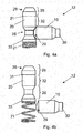
- Fig. 4a shows the locking cage 12 in detail in the assembled and non-blocking state.
- the locking pin 20 is held at its lower end (the spring holder 33) by a compression spring 21 and pushed upwards.
- This pressure is counteracted by the follower pin 10, which has a dome 29 at one end, which engages in a constriction region 26 of the locking bolt 20 and holds the locking bolt 20 in position.
- the scanning pin 10 has a Abtastnase 30, which has a smaller diameter than the Abtastroy 10.
- the Abtastting 10 has a diameter of 3mm +/- 0.02mm and the Abtastnase 30 has a diameter of 2mm +/- 0.02mm.
- the locking bolt 20 Adjacent to the constriction region 26, the locking bolt 20 has a central part 32, which is designed with a diameter slightly smaller than the rest of the locking bolt 20.
- the middle part 32 has a diameter of 3 mm +/- 0.05 mm
- the spring holder 33 has a diameter of 3.1 mm +/- 0.02 mm.
- the constriction 26 is designed with a diameter of 2mm +/- 0.02mm.
- the free end of the locking bolt 20 is designed as a locking head 28 having a slightly higher diameter, so that a step 31 is formed.
- the diameter of the locking head is 3.1 mm +/- 0.02 mm, thus the height of the rotating step is about 0.05 mm.
- the locking pin 20 is also formed at its end with a dome 29 to ensure a smooth engagement in the counterbores of the core extension.
- the crests are preferably embodied at an angle of approximately 60 ° to the longitudinal axis of the scanning pin 10 or locking bolt 20.
- Fig. 4b shows the locking circlip in the blocking state: The sensing pin 10 has moved axially outward and released the locking pin, whereby this is pressed by the compression spring 21 upwards and engages with its locking head 28 in the counterbore 25 of the core extension.
Landscapes
- Engineering & Computer Science (AREA)
- Mechanical Engineering (AREA)
- Lock And Its Accessories (AREA)
- Actuator (AREA)
- Snaps, Bayonet Connections, Set Pins, And Snap Rings (AREA)
- Molds, Cores, And Manufacturing Methods Thereof (AREA)
- Unwinding Webs (AREA)
Abstract
Description
- Die Erfindung betrifft einen Schließzylinder mit einem in einem Schließzylindermodul drehbaren Zylinderkern und einer Sicherungszuhaltung zur Blockierung beim Auf- oder Abbrechen des Schließzylindermoduls.
- Schließzylinder mit einem Schließzylindermodul, in dem sich ein drehbarer und sperrbarer Zylinderkern befindet, sind aus dem Stand der Technik bekannt. Ein wesentliches Sicherheitsproblem derartiger Schließzylinder besteht darin, dass der Schließzylinder in der Regel nicht exakt auf die Dicke der zu sperrenden Tür angepasst werden kann, sondern einige Millimeter bis Zentimeter aus der Ebene der Tür hervorragt. Durch Ansetzen eines geeigneten Aufbruchwerkzeugs kann der Schließzylinder von außen abgebrochen und der Zylinderkern betätigt werden. Als Abhilfe ist es bekannt, Sicherheitsbeschläge in Form von Manschetten oder dergleichen an der Außenseite des Schlosses anzubringen, um das Ansetzen des Aufbruchwerkzeugs unmöglich zu machen. Derartige Sicherheitsbeschläge sind jedoch teuer und müssen an die Länge des Zylinders angepasst werden.
- Als Abhilfe dieses Problems ist es aus der
DE 200 21 352 U1 bekannt, eine Sicherungszuhaltung zur Blockierung des Zylinderkerns vorzusehen, die in Kombination mit einer Sollbruchstelle im Zylindergehäuse beim Abbrechen des Zylindergehäuses aktiviert wird und die Drehung des Zylinderkerns blockiert. Nach dem Stand der Technik ist diese Sicherungszuhaltung im Zylindergehäuse vorgesehen und umfasst einen Verriegelungsbolzen, der unmittelbar neben und axial oder versetzt zu den Gehäuse- bzw. Kemstiften des Zylinderschlosses angeordnet ist. Eine Sollbruchstelle im Zylindergehäuse sorgt dafür, dass bei Einwirken einer äußeren Kraft auf das Gehäuse dieses an einer definierten Stelle bricht und die Scherungszuhaltung aktiviert wird. - Ein Problem dieser Vorrichtung aus dem Stand der Technik besteht darin, dass das Zylindergehäuse zur Aufnahme der Sicherungszuhaltung ausgeführt sein muss. Dies bedeutet in der Praxis, dass für die unterschiedlichsten Dimensionen der Zylindergehäuse Ausführungen mit und ohne Sicherungszuhaltung produziert und auf Lager gehalten werden müssen. Dies bedeutet einen erhöhten logistischen und produktionstechnischen Aufwand. Darüber hinaus wird das Zylindergehäuse durch die zusätzlichen Bohrungen und Aussparungen zur Aufnahme der Sicherungszuhaltung unnötig geschwächt, was schlussendlich der Sicherheit des Schlosses abträglich ist.
- Die Aufgabe der vorliegenden Erfindung besteht darin, die Nachteile der bekannten Vorrichtungen zu beheben und ein Zylinderschloss mit Sicherheitszuhaltung zu realisieren, das einfach in der Herstellung ist und modular mit anderen, bereits vorhandenen Zylinderschlössern kombiniert werden kann, ohne Kompromisse beim Grad an Sicherheit gegenüber Aufbruchsversuchen eingehen zu müssen.
- Diese Aufgabe wird erfindungsgemäß dadurch gelöst, dass die Sicherungszuhaltung in einer Abtasteinheit angrenzend an das Schließzylindermodul angeordnet ist und zum Abtasten der Position des Schließzylindermoduls einen Abtaststift sowie zur Blockierung einen Verriegelungsbolzen umfasst.
- Indem sich die Sicherungszuhaltung - vorzugsweise zur Gänze - in einer separaten Abtasteinheit befindet, kann im Prinzip jedes kompatible Zylinderschloss mit einer entsprechenden Sicherungszuhaltung aufgerüstet werden. Das Vorhandensein oder Fehlen des Schließzylindermoduls (in der Regel der außenliegende Teil des Zylindergehäuses) wird direkt durch einen Abtaststift detektiert, der seinerseits beim Fehlen des Gehäuseteils die Blockierung des Zylinderkerns veranlasst.
- Erfindungsgemäß kann vorgesehen sein, dass die Sicherungszuhaltung zur Blockierung einer angrenzend an den Zylinderkern vorgesehenen Kernverlängerung ausgeführt ist. Dies hat den Vorteil, dass Gehäuse- und Kemstiftanordnung in den Gehäuseteilen bzw. im Zylinderkern nicht verändert werden müssen, da auch das blockierende Element zum Bockieren nicht in den Zylinderkern, sondern in einen separaten Teil, eben die Kemverlängerung, eingreift.
- Das Schließzylindermodul kann ein Gehäuseteil, und die Abtasteinheit eine die Sicherungszuhaltung aufnehmende Gehäuseverlängerung umfassen. Dabei kann das Gehäuseteil in bekannter Weise ausgeführt sein. Herkömmliche Gehäuseverlängerungen können in einfacher Weise angepasst werden, um die Sicherungszuhaltung aufzunehmen. Die Kernverlängerung kann in bekannter Weise eine Kupplungsverlängerung umfassen.
- Erfindungsgemäß kann weiters vorgesehen sein, dass der Abtaststift in einer Bohrung der Gehäuseverlängerung derart beweglich gelagert ist, dass er im montierten Zustand an einem Ende an das Schließzylindermodul angrenzt und an einem anderen Ende in den beweglich gelagerten, unter Federspannung stehenden Verriegelungsbolzen eingreift. Dadurch kann der Abtaststift als Detektor für das Abbrechen bzw. Entfernen des Schließzylindermoduls dienen. Vorzugsweise kann vorgesehen sein, dass der Verriegelungsbolzen einen Einschnürungsbereich aufweist, der derart mit einer Endkuppe des Abtaststifts korrespondiert, dass der unter Federspannung stehende Verriegelungsbolzen bei Bewegung des Abtaststifts in der Bohrung freigegeben wird. Der Verriegelungsbolzen kann aber auch auf andere Art mit dem Abtaststift in Verbindung stehen, es muss lediglich gewährleistet sein, dass bei Entfernung des Schließzylindermoduls der Abtaststift den Verriegelungsbolzen freigibt.
- Der Verriegelungsbolzen kann vorzugsweise eine Endkuppe aufweisen, die bei Freigabe des Verriegelungsbolzens zum Eingriff in eine Senkbohrung einer mit dem Zylinderkern verbundenen oder verbindbaren Kernverlängerung ausgeführt ist. Dadurch kann der Verriegelungsbolzen die Kernverlängerung sperren. Eine derartige Kernverlängerung kann vorzugsweise in der Gehäuseverlängerung drehbar gelagert sein. Eine Betätigung des Zylinderkerns durch Drehen der Kernverlängerung von außen wird durch den Verriegelungsbolzen unmöglich gemacht.
- Das Gehäuseteil als Bestandteil des Schließzylindermoduls und die Gehäuseverlängerung können vorzugsweise auf einer gemeinsamen Achse angebracht sein oder anbringbar sein, wobei die Achse eine, ihre mechanische Festigkeit verringernde, Sollbruchstelle, vorzugsweise in Form einer Einschnürung aufweist. Die Sollbruchstelle kann vorzusweise in Form einer Ringnut realisiert werden.
- Beim versuchten Abbrechen des äußeren Gehäuseteils bzw. Schließzylindermoduls bricht nicht das Gehäuse, sondern die mit dem Gehäuse fest verbundene Achse, und das Gehäuse wird nicht beschädigt, sondern fällt mit der zerbrochenen Achse vom Schloss ab. Dies ist auch insofern vorteilhaft, als es produktionstechnisch einfacher ist, einen Drehteil wie die Achse mit einer Sollbruchstelle zu versehen, als ein komplexes Bauteil wie das Gehäuse selbst, welches zur festen Aufnahme des Zylinderkerns dienen muss. Die Gehäuseteile können durch Schraubverbindungen und/oder formschlüssige Steckverbindungen mit der Achse fest verbunden sein.
- Der Abtaststift kann weiters zum Abtasten der Position des Schließzylindermoduls an einer seiner Enden eine Abtastnase mit reduziertem Durchmesser aufweisen. Vorzugsweise wird der Abtaststift im Inneren der Gehäuseverlängerung in einer Bohrung verschiebbar gelagert, deren Achse im Wesentlichen parallel zur Achse des Zylinderschlosses verläuft. Die Bohrung kann vorzugsweise mit abgestuften Durchmessern ausgeführt sein, um zu verhindern, dass der Abtaststift von außen aus der Bohrung entfernt wird.
- Der Verriegelungsbolzen kann einen Verriegelungskopf mit Endkuppe zum Eingriff in eine Senkbohrung einer Kernverlängerung und einen Mittelteil aufweisen, wobei der Verriegelungskopf einen größeren Durchmesser als der Mittelteil aufweist, wodurch zwischen Verriegelungskopf und Mittelteil eine Kante gebildet ist. Dass der Verriegelungsbolzen in die Kernverlängerung, und nicht in den Kern selbst eingreift, hat den Vorteil, dass die Konstruktion einfach bei bestehenden Schlössern nachgerüstet werden kann.
- Die Kante zwischen Verriegelungskopf und Mittelteil, die üblicherweise in Form eines Sprungs im Durchmesser von 0,05 bis 0,2, vorzugsweise 0,1 mm, realisiert wird, dient dazu, dass der Verriegelungsbolzen im eingeschnappten (blockierten) Zustand nicht durch Anwenden der Schlagmethode aus der Kernverlängerung entfernt werden kann. Sobald der Verriegelungsbolzen in der Kernverlängerung steckt und die Kernverlängerung von außen verdreht wird, bleibt der Verriegelungsbolzen an der Kante hängen, und ein Herausschlagen aus der Kernverlängerung ist unmöglich. Erfindungsgemäß kann vorgesehen sein, dass die Kernverlängerung umfangsseitig mehrere Senkbohrungen zur Aufnahme des Verriegelungsbolzens aufweist. Dies erleichtert den Zusammenbau, da die Kernverlängerung in jeder beliebigen Position eingesetzt werden kann.
- Es kann weiters vorgesehen sein, dass die Gehäuseverlängerung über eine rechteckige Ausnehmung formschlüssig und mit einem zusätzlichen Sicherungsstift mit der Achse verbindbar ist. Weiters kann die Achse Bohrungen zur Verbindung mit den Gehäuseteilen und der Gehäuseverlängerung sowie in bekannter Weise eine Stulpschraubenbohrung aufweisen.
- Die als Sollbruchstelle dienende Einschnürung der Achse kann vorzugsweise als umlaufende Ringnut ausgebildet sein und im Übergangsbereich zwischen Gehäuseverlängerung und zweitem Gehäuseteil derart angeordnet sein, dass im zusammengebauten Zustand eine äußere Krafteinwirkung auf den zweiten Gehäuseteil direkt auf die Ringnut abgeleitet wird. Damit wird sichergestellt, dass die Achse bricht, und nicht das Gehäuse oder der Kern.
- Weitere erfindungsgemäße Merkmale ergeben sich aus den Ansprüchen, der Beschreibung und den Zeichnungen.
- Im Folgenden wird die Erfindung an Hand eines erfindungsgemäßen Ausführungsbeispiels näher erläutert. Es zeigen
- Fig. 1:
- das erfindungsgemäße Zylinderschloss in Explosionsdarstellung;
- Fig. 2a-2b:
- eine schematische Ansicht eines Ausführungsbeispiels eines erfindungsgemäßen Zylinderschlosses;
- Fig. 3a - 3b:
- das erfindungsgemäße Zylinderschloss im Querschnitt;
- Fig. 4a-4b:
- die Sicherheitszuhaltung eines erfindungsgemäßen Zylinderschlosses in Detailansicht.
-
Fig. 1 zeigt eine Explosionsdarstellung eines erfindungsgemäßen Schließzylinders. Der Schließzylinder 1 umfasst eine Achse 5, auf der ein erstes Gehäuseteil 2a und ein zweites Gehäuseteil 2b angebracht sind. Zu diesem Zweck ist die Achse 5 mit Bohrungen 17 versehen, in die Schrauben 16 zur Fixierung der Gehäuseteile 2a, 2b einführbar sind. Die Achse 5 verfügt weiters über eine Stulpschraubenbohrung 6 zur Fixierung des Schließzylinders im Einstemmschloss. Das Gehäuseteil 2b trägt einen Zylinderkern 3 und bildet mit diesem das Schließzylindermodul 27. - Direkt angrenzend zur Bohrung 17 und somit naheliegend zum Endbereich des zweiten Gehäuseteils 2b weist die Achse 5 eine Einschnürung 8 auf, die als Sollbruchstelle dient und als umlaufende Ringnut geringer Tiefe ausgeführt ist. Die Tiefe der Ringnut ist so gewählt, dass einerseits die Achse stabil genug bleibt, um herkömmlichen Belastungen zu widerstehen, jedoch beim Versuch, das Gehäuse abzubrechen, sicher eine Bruchstelle bildet.
- Die Achse 5 verfügt weiters über Abflachungen 14, die eine rechteckige Form bilden, welche zur formschlüssigen Aufnahme einer Gehäuseverlängerung 7 dienen. Dazu hat die Gehäuseverlängerung 7 eine entsprechend korrespondierende Ausnehmung 22, sowie eine Bohrung 19 zur Aufnahme eines Sicherungsstiftes 18, wobei in der Achse 5 eine fluchtende Bohrung 15 vorgesehen ist.
- Die Gehäuseteile 2a und 2b beherbergen Zylinderkerne 3, die mit einem Schließbart 4 gekoppelt sind bzw. gekoppelt werden können. In den Zylinderkernen 3 und den Gehäuseteilen 2a, 2b befinden sich in bekannter Weise Gehäusestifte und Kernstifte (nicht dargestellt) zum Sperren des Zylinderschlosses.
- Zwischen Schließbart 4 und Schließzylindermodul 27 ist eine Abtasteinheit 34 eingefügt, welche eine Gehäuseverlängerung 7 umfasst. Die Gehäuseverlängerung 7 ist zwischen den beiden Gehäuseteilen 2a und 2b vorgesehen und nimmt eine Kernverlängerung 11 auf, die die beiden Zylinderkerne über Kerneingriffsvorsprünge 24 mit dem Schließbart bzw. miteinander koppelt. Zu diesem Zweck ist eine Kupplungsverlängerung 13 in die Kernverlängerung 11 eingeschoben.
- Derartige Gehäuseverlängerungen zur Anpassung des Zylinderschlosses an die Dicke eines Türblattes sind aus dem Stand der Technik grundsätzlich bekannt.
- Im unteren Bereich der Gehäuseverlängerung 7 ist die eigentliche Sicherungszuhaltung 12 vorgesehen, umfassend einen Verriegelungsbolzen 20, eine Druckfeder 21 und einen Abtaststift 10.
- Der Abtaststift 10 ist in einer im Wesentlichen parallel zur Achse 5 ausgerichteten Bohrung beweglich gelagert und kann durch eine Abtastöffnung 23 das Vorhandensein oder Fehlen des zweiten Gehäuseteils 2b detektieren. An seinem anderen Ende greift der Abtaststift 10 in einen Einschnürungsbereich 26 des Verriegelungsbolzens 20 ein, der unter Federspannung der Druckfeder 21 in einer Bohrung, die im Wesentlichen radial zur Achse 5 in der Gehäuseverlängerung 7 vorgesehen ist, gehalten ist. Sobald der Abtaststift 10 seine Position verlässt, wird der Verriegelungsbolzen 20 freigegeben und greift an seinem oberen Ende in eine Senkbohrung 25 am äußeren Umfang der Kernverlängerung 11 ein. Dadurch wird die Bewegung der Kernverlängerung 11 blockiert.
-
Fig. 2a zeigt eine schematische Ansicht eines Ausführungsbeispiels eines erfindungsgemäßen Schließzylinders 1. Der Schließzylinder 1 ist als Doppelzylinder ausgeführt und verfügt über einen ersten Gehäuseteil 2a und einen zweiten Gehäuseteil 2b, die an einer gemeinsamen Achse 5 angebracht sind. Dazwischen befindet sich der Schließbart 4 und die Abtasteinheit 34, welche das Vorhandensein des Schließzylindermoduls 27 detektiert und eine Gehäuseverlängerung 7 umfasst. Die Achse 5 trägt in bekannter Weise die Stulpschraubenbohrung 6 zur Fixierung des Zylinderschlosses im Einstemmschloss und weist eine Einschnürung 8 auf, die als Sollbruchstelle dient. - Im Inneren der Gehäuseteile 2a, 2b sind Zylinderkerne 3 vorgesehen, die über eine Kernverlängerung 11 (nicht dargestellt) miteinander verkoppelt sind. Ein Schlüssel 9 ist in einen Schließkanal des Zylinderkerns 2 einführbar und betätigt den Zylinderkern und in Folge den Schließbart zum Sperren des Zylinderschlosses.
-
Fig. 2b zeigt das Zylinderschloss ausFig. 1 a im aufgebrochenen Zustand. Durch Ansetzen eines geeigneten Einbruchswerkzeuges wurde versucht, das Schließzylindermodul 27 in Form des äußeren zweiten Gehäuseteils 2b abzubrechen, um in Folge Zugriff auf den Zylinderkern bzw. die Zylinderkernverlängerung zu bekommen, und den Schließbart betätigen zu können. Statt dem Gehäuse ist jedoch die Achse 5 an der Einschnürung 8 gebrochen und gibt den Abtaststift 10 der Abtasteinheit 34 frei. Die Sicherungszuhaltung ist aktiviert und der Verriegelungsbolzen 20 blockiert jede Bewegung der Kernverlängerung 11. -
Fig. 3a zeigt das Zylinderschloss ausFig. 1 a im Querschnitt. In dieser Ansicht ist zu sehen, dass die Gehäuseverlängerung 7 eine Kernverlängerung 11 beinhaltet, die an eine Sicherheitszuhaltung 12 angrenzt.Fig. 3b zeigt das Zylinderschloss aufFig. 1 b im Querschnitt. Wenn das zweite Gehäuseteil 2b weggebrochen wird, gibt der Abtaststift 10 einen durch eine Druckfeder in der Gehäuseverlängerung 7 vorgespannten Verriegelungsbolzen 20 nach oben in eine Senkbohrung der Kernverlängerung 11 frei, wodurch diese gegen Drehung blockiert ist. -
Fig. 4a zeigt die Sicherungszuhaltung 12 im Detail im zusammengebauten und nicht blockierenden Zustand. Der Verriegelungsbolzen 20 wird an seinem unteren Ende (der Federhalterung 33) durch eine Druckfeder 21 gehalten und nach oben gedrückt. Diesem Druck wirkt der Abtaststift 10 entgegen, der an einem Ende eine Kuppe 29 aufweist, die in einen Einschnürungsbereich 26 des Verriegelungsbolzens 20 eingreift und den Verriegelungsbolzen 20 in Position hält. An seinem anderen Ende weist der Abtaststift 10 eine Abtastnase 30 auf, die einen geringeren Durchmesser als der Abtaststift 10 aufweist. - Im vorliegenden Ausführungsbeispiel weist der Abtaststift 10 einen Durchmesser von 3mm +/- 0,02mm und die Abtastnase 30 einen Durchmesser von 2mm +/- 0,02mm auf. Angrenzend an den Einschnürungsbereich 26 weist der Verriegelungsbolzen 20 einen Mittelteil 32 auf, der mit leicht geringerem Durchmesser als der Rest des Verriegelungsbolzens 20 ausgeführt ist. Im vorliegenden Beispiel hat der Mittelteil 32 einen Durchmesser von 3mm +/-0,05mm, während die Federhalterung 33 einen Durchmesser von 3,1 mm +/- 0,02mm aufweist.
- Die Einschnürung 26 ist mit einem Durchmesser von 2mm +/-0,02mm ausgeführt. Das freie Ende des Verriegelungsbolzens 20 ist als Verriegelungskopf 28 ausgeführt, der einen leicht höheren Durchmesser aufweist, damit eine Stufe 31 gebildet wird. Im vorliegenden Ausführungsbeispiel beträgt der Durchmesser des Verriegelungskopfes 3,1 mm +/- 0,02mm, somit beträgt die Höhe der umlaufenden Stufe ca. 0,05mm. Wie der Abtaststift 10 ist auch der Verriegelungsbolzen 20 an seinem Ende mit einer Kuppe 29 ausgeführt, um ein reibungsfreies Eingreifen in die Senkbohrungen der Kernverlängerung zu gewährleisten. Die Kuppen sind vorzugsweise in einem Winkel von etwa 60° zur Längsachse des Abtaststiftes 10 bzw. Verriegelungsbolzens 20 ausgeführt.
-
Fig. 4b zeigt die Sicherungszuhaltung im blockierenden Zustand: Der Abtaststift 10 hat sich axial nach außen bewegt und den Verriegelungsbolzen freigegeben, wodurch dieser durch die Druckfeder 21 nach oben gedrückt wird und mit seinem Verriegelungskopf 28 in die Senkbohrung 25 der Kernverlängerung eingreift. - Die Erfindung erstreckt sich nicht nur auf die beispielhaft angeführten Ausführungsbeispiele, sondern umfasst auch weitere Ausführungen im Rahmen der Patentansprüche. Insbesondere ist die Erfindung nicht auf die konkret beschriebene Ausführung der Sicherungszuhaltung beschränkt.
-
- 1
- Schließzylinder
- 2a
- Erster Gehäuseteil
- 2b
- Zweiter Gehäuseteil
- 3
- Zylinderkern
- 4
- Schließbart
- 5
- Achse
- 6
- Stulpschraubenbohrung
- 7
- Gehäuseverlängerung
- 8
- Einschnürung
- 9
- Schlüssel
- 10
- Abtaststift
- 11
- Kernverlängerung
- 12
- Sicherungszuhaltung
- 13
- Kupplungsverlängerung
- 14
- Abflachungen der Achse
- 15
- Bohrung
- 16
- Fixierschraube
- 17
- Bohrung
- 18
- Sicherungsstift
- 19
- Bohrung
- 20
- Verriegelungsbolzen
- 21
- Druckfeder
- 22
- Ausnehmung
- 23
- Abtastöffnung
- 24
- Kerneingriffsvorsprung
- 25
- Senkbohrung
- 26
- Einschnürungsbereich
- 27
- Schließzylindermodul
- 28
- Verriegelungskopf
- 29
- Endkuppe
- 30
- Abtastnase
- 31
- Kante
- 32
- Mittelteil
- 33
- Federhalterung
- 34
- Abtasteinheit
Claims (14)
- Schließzylinder (1) mit einem in einem Schließzylindermodul (27) drehbaren Zylinderkern (3) und einer Sicherungszuhaltung (12) zur Blockierung beim Aufoder Abbrechen des Schließzylindermoduls (27),
dadurch gekennzeichnet, dass
die Sicherungszuhaltung (12) in einer Abtasteinheit (34) angrenzend an das Schließzylindermodul (27) angeordnet ist und zum Abtasten der Position des Schließzylindermoduls (27) einen Abtaststift (10) sowie zur Blockierung einen Verriegelungsbolzen (20) umfasst. - Schließzylinder (1) nach Anspruch 1, dadurch gekennzeichnet, dass die Sicherungszuhaltung (12) zur Blockierung einer angrenzend an den Zylinderkern (3) vorgesehenen Kernverlängerung (11) ausgeführt ist.
- Schließzylinder (1) nach einem der vorhergehenden Ansprüche, dadurch gekennzeichnet, dass das Schließzylindermodul (27) ein Gehäuseteil (2b), und die Abtasteinheit (34) eine die Sicherungszuhaltung (12) aufnehmende Gehäuseverlängerung (7) umfasst.
- Schließzylinder (1) nach einem der Ansprüche 2 oder 3, dadurch gekennzeichnet, dass die Kernverlängerung (11) eine Kupplungsverlängerung (13) umfasst.
- Schließzylinder (1) nach einem der Ansprüche 3 oder 4, dadurch gekennzeichnet, dass der Abtaststift (10) in einer Bohrung (23) der Gehäuseverlängerung (7) derart beweglich gelagert ist, dass er im montierten Zustand an einem Ende an das Schließzylindermodul (27) angrenzt und an einem anderen Ende in den beweglich gelagerten, unter Federspannung stehenden Verriegelungsbolzen (20) eingreift.
- Schließzylinder (1) nach einem der vorhergehenden Ansprüche, dadurch gekennzeichnet, dass der Verriegelungsbolzen (20) einen Einschnürungsbereich (26) aufweist, der derart mit einer Endkuppe (29) des Abtaststifts (10) korrespondiert, dass der unter Federspannung stehende Verriegelungsbolzen (20) bei Bewegung des Abtaststifts (10) in der Bohrung (23) freigegeben wird.
- Schließzylinder (1) nach einem der Ansprüche 2 bis 6, dadurch gekennzeichnet, dass der Verriegelungsbolzen (20) eine Endkuppe (29) aufweist, die bei Freigabe des Verriegelungsbolzens zum Eingriff in eine Senkbohrung (25) der Kernverlängerung (11) ausgeführt ist.
- Schließzylinder (1) nach einem der Ansprüche 3 bis 7, dadurch gekennzeichnet, dass das Gehäuseteil (2b) und die Gehäuseverlängerung (7) auf einer gemeinsamen Achse (5) angebracht oder anbringbar sind, wobei die Achse (5) eine, ihre mechanische Festigkeit verringernde, Sollbruchstelle, vorzugsweise in Form einer Einschnürung (8) aufweist.
- Schließzylinder (1) nach einem der vorhergehenden Ansprüche, dadurch gekennzeichnet, dass der Abtaststift (10) zum Abtasten der Position des Schließzylindermoduls (27) eine Abtastnase (30) mit reduziertem Durchmesser aufweist.
- Schließzylinder (1) nach einem der vorhergehenden Ansprüche, dadurch gekennzeichnet, dass der Verriegelungsbolzen (20) einen Verriegelungskopf (28) mit Endkuppe (29) zum Eingriff in eine Senkbohrung (25) und einen Mittelteil (32) aufweist, wobei der Verriegelungskopf (28) einen größeren Durchmesser als der Mittelteil (32) aufweist, wodurch zwischen Verriegelungskopf (28) und Mittelteil (32) eine Kante (31) gebildet ist.
- Schließzylinder (1) nach einem der Ansprüche 2 bis 9, dadurch gekennzeichnet, dass die Kernverlängerung (11) umfangsseitig mehrere Senkbohrungen (25) zur Aufnahme des Verriegelungsbolzens (20) aufweist.
- Schließzylinder (1) nach einem der Ansprüche 8 bis 11, dadurch gekennzeichnet, dass die Gehäuseverlängerung (7) über eine rechteckige Ausnehmung (22) und einen Sicherungsstift (18) mit der Achse (5) verbindbar ist.
- Schließzylinder (1) nach einem der Ansprüche 8 bis 12, dadurch gekennzeichnet, dass die Achse (5) Bohrungen (15, 17) zur Verbindung mit den Gehäuseteilen (2a, 2b) und der Gehäuseverlängerung (7) sowie eine Stulpschraubenbohrung (6) aufweist.
- Schließzylinder (1) nach einem der Ansprüche 8 bis 13, dadurch gekennzeichnet, dass die Einschnürung (8) der Achse (5) als umlaufende Ringnut ausgebildet ist und im Übergangsbereich zwischen Gehäuseverlängerung (7) und zweitem Gehäuseteil (2b) derart angeordnet ist, dass im zusammengebauten Zustand eine äußere Krafteinwirkung auf den zweiten Gehäuseteil (2b) direkt auf die Ringnut abgeleitet wird.
Applications Claiming Priority (1)
| Application Number | Priority Date | Filing Date | Title |
|---|---|---|---|
| ATA1190/2012A AT513607B1 (de) | 2012-11-08 | 2012-11-08 | Zylinderschloss |
Publications (3)
| Publication Number | Publication Date |
|---|---|
| EP2730727A2 true EP2730727A2 (de) | 2014-05-14 |
| EP2730727A3 EP2730727A3 (de) | 2016-12-14 |
| EP2730727B1 EP2730727B1 (de) | 2021-03-17 |
Family
ID=49578099
Family Applications (1)
| Application Number | Title | Priority Date | Filing Date |
|---|---|---|---|
| EP13191785.8A Active EP2730727B1 (de) | 2012-11-08 | 2013-11-06 | Zylinderschloss |
Country Status (2)
| Country | Link |
|---|---|
| EP (1) | EP2730727B1 (de) |
| AT (1) | AT513607B1 (de) |
Cited By (13)
| Publication number | Priority date | Publication date | Assignee | Title |
|---|---|---|---|---|
| GB2515054A (en) * | 2013-06-12 | 2014-12-17 | Fed Lock Co Ltd | Safety lock core assembly |
| EP2963209A1 (de) * | 2014-07-01 | 2016-01-06 | Xu, JuXiang | Verbesserte struktur eines schliesszylinders |
| GB2531900A (en) * | 2014-09-06 | 2016-05-04 | Xu Juxiang | Lock cylinder mechanism capable of preventing violent damage |
| GB2545389A (en) * | 2015-09-07 | 2017-06-21 | Banham Patent Locks Ltd | Security mechanism |
| WO2018051094A1 (en) * | 2016-09-15 | 2018-03-22 | Apecs Consult Limited | Anti-snap cylinder lock |
| IT201700065487A1 (it) * | 2017-06-13 | 2018-12-13 | Rielda Serrature S P A | Serratura a cilindro con bloccaggio alla rotazione in caso di spezzamento |
| EP3517713A1 (de) * | 2018-01-29 | 2019-07-31 | C. Ed. Schulte Gesellschaft mit beschränkter Haftung Zylinderschlossfabrik | Schliesseinrichtung |
| EP3550097A1 (de) | 2018-04-06 | 2019-10-09 | C. Ed. Schulte Gesellschaft mit beschränkter Haftung Zylinderschlossfabrik | Schliesseinrichtung |
| IT201800009309A1 (it) | 2018-10-10 | 2020-04-10 | Omec Serrature Spa | Cilindro per meccanismi di azionamento |
| EP3802997A4 (de) * | 2018-05-28 | 2021-06-23 | Kale Kilit ve Kalip Sanayi Anonim Sirketi | Zylinderschloss mit erhöhter sicherheit gegen einbruchsversuche |
| WO2021145770A1 (en) | 2020-01-17 | 2021-07-22 | M & C Protect B.V. | Cylinder lock |
| GB202402827D0 (en) | 2024-02-28 | 2024-04-10 | Era Home Security Ltd | High security lock cylinder |
| EP4372189A1 (de) | 2022-11-18 | 2024-05-22 | ERA Home Security Limited | Hochsicherheitsschliesszylinder |
Citations (1)
| Publication number | Priority date | Publication date | Assignee | Title |
|---|---|---|---|---|
| DE20021352U1 (de) | 2000-12-16 | 2001-03-22 | Aug. Winkhaus GmbH & Co. KG., 48291 Telgte | Schließzylinder |
Family Cites Families (5)
| Publication number | Priority date | Publication date | Assignee | Title |
|---|---|---|---|---|
| DE8908212U1 (de) * | 1988-11-12 | 1989-10-12 | Mundhenke, Erich, 3252 Bad Münder | Zylinderschloß |
| GB2474371B (en) * | 2008-06-26 | 2011-11-16 | Avocet Hardware Ltd | A cylinder lock |
| GB2461297A (en) * | 2008-06-26 | 2009-12-30 | Avocet Hardware Ltd | Lock with additional security mechanism and clutch |
| DE102010043965A1 (de) * | 2010-11-16 | 2012-05-16 | Aug. Winkhaus Gmbh & Co. Kg | Elektronischer Sperrmechanismus |
| ES2718300T3 (es) * | 2010-12-17 | 2019-07-01 | Talleres Escoriaza Sa | Dispositivo de seguridad para cilindros de cerradura |
-
2012
- 2012-11-08 AT ATA1190/2012A patent/AT513607B1/de not_active IP Right Cessation
-
2013
- 2013-11-06 EP EP13191785.8A patent/EP2730727B1/de active Active
Patent Citations (1)
| Publication number | Priority date | Publication date | Assignee | Title |
|---|---|---|---|---|
| DE20021352U1 (de) | 2000-12-16 | 2001-03-22 | Aug. Winkhaus GmbH & Co. KG., 48291 Telgte | Schließzylinder |
Cited By (21)
| Publication number | Priority date | Publication date | Assignee | Title |
|---|---|---|---|---|
| GB2515054A (en) * | 2013-06-12 | 2014-12-17 | Fed Lock Co Ltd | Safety lock core assembly |
| EP2963209A1 (de) * | 2014-07-01 | 2016-01-06 | Xu, JuXiang | Verbesserte struktur eines schliesszylinders |
| GB2531900A (en) * | 2014-09-06 | 2016-05-04 | Xu Juxiang | Lock cylinder mechanism capable of preventing violent damage |
| GB2531900B (en) * | 2014-09-06 | 2018-06-27 | Xu Juxiang | Lock cylinder mechanism capable of preventing violent damage |
| GB2545389A (en) * | 2015-09-07 | 2017-06-21 | Banham Patent Locks Ltd | Security mechanism |
| GB2545389B (en) * | 2015-09-07 | 2021-06-23 | Banham Patent Locks Ltd | Security mechanism |
| WO2018051094A1 (en) * | 2016-09-15 | 2018-03-22 | Apecs Consult Limited | Anti-snap cylinder lock |
| IT201700065487A1 (it) * | 2017-06-13 | 2018-12-13 | Rielda Serrature S P A | Serratura a cilindro con bloccaggio alla rotazione in caso di spezzamento |
| EP3789568A1 (de) | 2018-01-29 | 2021-03-10 | C. Ed. Schulte Gesellschaft mit beschränkter Haftung Zylinderschlossfabrik | Schliesseinrichtung |
| EP3517713A1 (de) * | 2018-01-29 | 2019-07-31 | C. Ed. Schulte Gesellschaft mit beschränkter Haftung Zylinderschlossfabrik | Schliesseinrichtung |
| DE102018101896A1 (de) | 2018-01-29 | 2019-08-01 | C. Ed. Schulte Gmbh Zylinderschlossfabrik | Schließeinrichtung |
| DE102018108159A1 (de) | 2018-04-06 | 2019-10-10 | C. Ed. Schulte Gmbh Zylinderschlossfabrik | Schließeinrichtung |
| EP3550097A1 (de) | 2018-04-06 | 2019-10-09 | C. Ed. Schulte Gesellschaft mit beschränkter Haftung Zylinderschlossfabrik | Schliesseinrichtung |
| EP3802997A4 (de) * | 2018-05-28 | 2021-06-23 | Kale Kilit ve Kalip Sanayi Anonim Sirketi | Zylinderschloss mit erhöhter sicherheit gegen einbruchsversuche |
| EP3636860A1 (de) | 2018-10-10 | 2020-04-15 | OMEC Serrature S.P.A. | Zylinder für betätigungsmechanismen |
| IT201800009309A1 (it) | 2018-10-10 | 2020-04-10 | Omec Serrature Spa | Cilindro per meccanismi di azionamento |
| WO2021145770A1 (en) | 2020-01-17 | 2021-07-22 | M & C Protect B.V. | Cylinder lock |
| NL2024697B1 (nl) * | 2020-01-17 | 2021-09-08 | M & C Protect B V | Cilinderslot |
| EP4372189A1 (de) | 2022-11-18 | 2024-05-22 | ERA Home Security Limited | Hochsicherheitsschliesszylinder |
| GB202402827D0 (en) | 2024-02-28 | 2024-04-10 | Era Home Security Ltd | High security lock cylinder |
| GB2638702A (en) | 2024-02-28 | 2025-09-03 | Era Home Security Ltd | High security lock cylinder |
Also Published As
| Publication number | Publication date |
|---|---|
| EP2730727B1 (de) | 2021-03-17 |
| AT513607A4 (de) | 2014-06-15 |
| EP2730727A3 (de) | 2016-12-14 |
| AT513607B1 (de) | 2014-06-15 |
Similar Documents
| Publication | Publication Date | Title |
|---|---|---|
| AT513607B1 (de) | Zylinderschloss | |
| DE69926773T2 (de) | Zylinderschloss mit einbruchssicherung | |
| EP3153648B1 (de) | Hangschloss | |
| DE2544692B2 (de) | Zylinderschloß | |
| AT14128U1 (de) | Schließzylinder | |
| DE102013222422A1 (de) | Hangschloss | |
| DE69602920T2 (de) | Zylinderschlosseinsatz | |
| EP2218850B1 (de) | Schließsystem mit Kupplungseinrichtung für einen zwei Zylinderkerne beinhaltenden Doppelschließzylinder mit Not- und Gefahrenfunktion und mit zugeordneten Schlüssel | |
| DE102015001960A1 (de) | Schliesszylinder mit zwei auf gleicher Achse beabstandet zueinander angeordneten Schliessnasen | |
| EP2754790B1 (de) | Element mit selbstzentrierendem Beschlag für Fenster oder Türen | |
| EP2264267B1 (de) | Schloss | |
| EP3517713A1 (de) | Schliesseinrichtung | |
| EP0036141A1 (de) | Steckschlüsselbetätigbare Arretierungsvorrichtung | |
| DE102015121175A1 (de) | Sicherheitsbeschlag für Panikschloss | |
| EP3070236B1 (de) | Notentriegelungsvorrichtung | |
| DE102017008236B3 (de) | Sicherungsvorrichtung für ein Türschloss | |
| EP0585735B1 (de) | Schlosssicherung für Sicherheitsschliess-Zylinder | |
| DE2923598A1 (de) | Schliesszylinder und schliessanlage | |
| DE9210795U1 (de) | Sicherheitsbeschlag für mit einem Profilschließzylinder versehene Türschlösser | |
| DE202012000211U1 (de) | Vorrichtung zum einbruchsicheren Verschließen von Fenstern und Türen | |
| DE202015001220U1 (de) | Schließzylinder mit zwei auf gleicher Achse beabstandet zueinander angeordneten Schließnasen | |
| EP0861955B1 (de) | Verschliessbarer Fenstergriff | |
| EP0296337B1 (de) | Profilschliesszylinder | |
| DE7616431U1 (de) | Schutzvorrichtung fuer ein zylinderschloss | |
| DE102017009348B4 (de) | Fenster- & Türsicherung zur nachträglichen Sicherung für mindestens einen Flügel, eines Fensters oder einer Tür |
Legal Events
| Date | Code | Title | Description |
|---|---|---|---|
| PUAI | Public reference made under article 153(3) epc to a published international application that has entered the european phase |
Free format text: ORIGINAL CODE: 0009012 |
|
| 17P | Request for examination filed |
Effective date: 20131106 |
|
| AK | Designated contracting states |
Kind code of ref document: A2 Designated state(s): AL AT BE BG CH CY CZ DE DK EE ES FI FR GB GR HR HU IE IS IT LI LT LU LV MC MK MT NL NO PL PT RO RS SE SI SK SM TR |
|
| AX | Request for extension of the european patent |
Extension state: BA ME |
|
| PUAL | Search report despatched |
Free format text: ORIGINAL CODE: 0009013 |
|
| AK | Designated contracting states |
Kind code of ref document: A3 Designated state(s): AL AT BE BG CH CY CZ DE DK EE ES FI FR GB GR HR HU IE IS IT LI LT LU LV MC MK MT NL NO PL PT RO RS SE SI SK SM TR |
|
| AX | Request for extension of the european patent |
Extension state: BA ME |
|
| RIC1 | Information provided on ipc code assigned before grant |
Ipc: E05B 9/04 20060101AFI20161107BHEP Ipc: E05B 17/20 20060101ALI20161107BHEP |
|
| STAA | Information on the status of an ep patent application or granted ep patent |
Free format text: STATUS: REQUEST FOR EXAMINATION WAS MADE |
|
| R17P | Request for examination filed (corrected) |
Effective date: 20170613 |
|
| RBV | Designated contracting states (corrected) |
Designated state(s): AL AT BE BG CH CY CZ DE DK EE ES FI FR GB GR HR HU IE IS IT LI LT LU LV MC MK MT NL NO PL PT RO RS SE SI SK SM TR |
|
| STAA | Information on the status of an ep patent application or granted ep patent |
Free format text: STATUS: EXAMINATION IS IN PROGRESS |
|
| 17Q | First examination report despatched |
Effective date: 20180206 |
|
| GRAP | Despatch of communication of intention to grant a patent |
Free format text: ORIGINAL CODE: EPIDOSNIGR1 |
|
| STAA | Information on the status of an ep patent application or granted ep patent |
Free format text: STATUS: GRANT OF PATENT IS INTENDED |
|
| INTG | Intention to grant announced |
Effective date: 20201027 |
|
| GRAS | Grant fee paid |
Free format text: ORIGINAL CODE: EPIDOSNIGR3 |
|
| GRAA | (expected) grant |
Free format text: ORIGINAL CODE: 0009210 |
|
| STAA | Information on the status of an ep patent application or granted ep patent |
Free format text: STATUS: THE PATENT HAS BEEN GRANTED |
|
| RIN1 | Information on inventor provided before grant (corrected) |
Inventor name: BAUMHAUER, WALTER |
|
| AK | Designated contracting states |
Kind code of ref document: B1 Designated state(s): AL AT BE BG CH CY CZ DE DK EE ES FI FR GB GR HR HU IE IS IT LI LT LU LV MC MK MT NL NO PL PT RO RS SE SI SK SM TR |
|
| REG | Reference to a national code |
Ref country code: GB Ref legal event code: FG4D Free format text: NOT ENGLISH |
|
| RIN1 | Information on inventor provided before grant (corrected) |
Inventor name: BAUMHAUER, WALTER |
|
| REG | Reference to a national code |
Ref country code: CH Ref legal event code: EP |
|
| REG | Reference to a national code |
Ref country code: DE Ref legal event code: R096 Ref document number: 502013015563 Country of ref document: DE |
|
| REG | Reference to a national code |
Ref country code: IE Ref legal event code: FG4D Free format text: LANGUAGE OF EP DOCUMENT: GERMAN |
|
| REG | Reference to a national code |
Ref country code: AT Ref legal event code: REF Ref document number: 1372382 Country of ref document: AT Kind code of ref document: T Effective date: 20210415 |
|
| REG | Reference to a national code |
Ref country code: LT Ref legal event code: MG9D |
|
| PG25 | Lapsed in a contracting state [announced via postgrant information from national office to epo] |
Ref country code: HR Free format text: LAPSE BECAUSE OF FAILURE TO SUBMIT A TRANSLATION OF THE DESCRIPTION OR TO PAY THE FEE WITHIN THE PRESCRIBED TIME-LIMIT Effective date: 20210317 Ref country code: FI Free format text: LAPSE BECAUSE OF FAILURE TO SUBMIT A TRANSLATION OF THE DESCRIPTION OR TO PAY THE FEE WITHIN THE PRESCRIBED TIME-LIMIT Effective date: 20210317 Ref country code: GR Free format text: LAPSE BECAUSE OF FAILURE TO SUBMIT A TRANSLATION OF THE DESCRIPTION OR TO PAY THE FEE WITHIN THE PRESCRIBED TIME-LIMIT Effective date: 20210618 Ref country code: BG Free format text: LAPSE BECAUSE OF FAILURE TO SUBMIT A TRANSLATION OF THE DESCRIPTION OR TO PAY THE FEE WITHIN THE PRESCRIBED TIME-LIMIT Effective date: 20210617 Ref country code: NO Free format text: LAPSE BECAUSE OF FAILURE TO SUBMIT A TRANSLATION OF THE DESCRIPTION OR TO PAY THE FEE WITHIN THE PRESCRIBED TIME-LIMIT Effective date: 20210617 |
|
| REG | Reference to a national code |
Ref country code: NL Ref legal event code: MP Effective date: 20210317 |
|
| PG25 | Lapsed in a contracting state [announced via postgrant information from national office to epo] |
Ref country code: RS Free format text: LAPSE BECAUSE OF FAILURE TO SUBMIT A TRANSLATION OF THE DESCRIPTION OR TO PAY THE FEE WITHIN THE PRESCRIBED TIME-LIMIT Effective date: 20210317 Ref country code: LV Free format text: LAPSE BECAUSE OF FAILURE TO SUBMIT A TRANSLATION OF THE DESCRIPTION OR TO PAY THE FEE WITHIN THE PRESCRIBED TIME-LIMIT Effective date: 20210317 Ref country code: SE Free format text: LAPSE BECAUSE OF FAILURE TO SUBMIT A TRANSLATION OF THE DESCRIPTION OR TO PAY THE FEE WITHIN THE PRESCRIBED TIME-LIMIT Effective date: 20210317 |
|
| PG25 | Lapsed in a contracting state [announced via postgrant information from national office to epo] |
Ref country code: NL Free format text: LAPSE BECAUSE OF FAILURE TO SUBMIT A TRANSLATION OF THE DESCRIPTION OR TO PAY THE FEE WITHIN THE PRESCRIBED TIME-LIMIT Effective date: 20210317 |
|
| PG25 | Lapsed in a contracting state [announced via postgrant information from national office to epo] |
Ref country code: SM Free format text: LAPSE BECAUSE OF FAILURE TO SUBMIT A TRANSLATION OF THE DESCRIPTION OR TO PAY THE FEE WITHIN THE PRESCRIBED TIME-LIMIT Effective date: 20210317 Ref country code: LT Free format text: LAPSE BECAUSE OF FAILURE TO SUBMIT A TRANSLATION OF THE DESCRIPTION OR TO PAY THE FEE WITHIN THE PRESCRIBED TIME-LIMIT Effective date: 20210317 Ref country code: EE Free format text: LAPSE BECAUSE OF FAILURE TO SUBMIT A TRANSLATION OF THE DESCRIPTION OR TO PAY THE FEE WITHIN THE PRESCRIBED TIME-LIMIT Effective date: 20210317 Ref country code: CZ Free format text: LAPSE BECAUSE OF FAILURE TO SUBMIT A TRANSLATION OF THE DESCRIPTION OR TO PAY THE FEE WITHIN THE PRESCRIBED TIME-LIMIT Effective date: 20210317 |
|
| PG25 | Lapsed in a contracting state [announced via postgrant information from national office to epo] |
Ref country code: SK Free format text: LAPSE BECAUSE OF FAILURE TO SUBMIT A TRANSLATION OF THE DESCRIPTION OR TO PAY THE FEE WITHIN THE PRESCRIBED TIME-LIMIT Effective date: 20210317 Ref country code: PL Free format text: LAPSE BECAUSE OF FAILURE TO SUBMIT A TRANSLATION OF THE DESCRIPTION OR TO PAY THE FEE WITHIN THE PRESCRIBED TIME-LIMIT Effective date: 20210317 Ref country code: PT Free format text: LAPSE BECAUSE OF FAILURE TO SUBMIT A TRANSLATION OF THE DESCRIPTION OR TO PAY THE FEE WITHIN THE PRESCRIBED TIME-LIMIT Effective date: 20210719 Ref country code: ES Free format text: LAPSE BECAUSE OF FAILURE TO SUBMIT A TRANSLATION OF THE DESCRIPTION OR TO PAY THE FEE WITHIN THE PRESCRIBED TIME-LIMIT Effective date: 20210317 Ref country code: IS Free format text: LAPSE BECAUSE OF FAILURE TO SUBMIT A TRANSLATION OF THE DESCRIPTION OR TO PAY THE FEE WITHIN THE PRESCRIBED TIME-LIMIT Effective date: 20210717 Ref country code: RO Free format text: LAPSE BECAUSE OF FAILURE TO SUBMIT A TRANSLATION OF THE DESCRIPTION OR TO PAY THE FEE WITHIN THE PRESCRIBED TIME-LIMIT Effective date: 20210317 |
|
| REG | Reference to a national code |
Ref country code: DE Ref legal event code: R097 Ref document number: 502013015563 Country of ref document: DE |
|
| PLBE | No opposition filed within time limit |
Free format text: ORIGINAL CODE: 0009261 |
|
| STAA | Information on the status of an ep patent application or granted ep patent |
Free format text: STATUS: NO OPPOSITION FILED WITHIN TIME LIMIT |
|
| PG25 | Lapsed in a contracting state [announced via postgrant information from national office to epo] |
Ref country code: AL Free format text: LAPSE BECAUSE OF FAILURE TO SUBMIT A TRANSLATION OF THE DESCRIPTION OR TO PAY THE FEE WITHIN THE PRESCRIBED TIME-LIMIT Effective date: 20210317 Ref country code: DK Free format text: LAPSE BECAUSE OF FAILURE TO SUBMIT A TRANSLATION OF THE DESCRIPTION OR TO PAY THE FEE WITHIN THE PRESCRIBED TIME-LIMIT Effective date: 20210317 |
|
| 26N | No opposition filed |
Effective date: 20211220 |
|
| PG25 | Lapsed in a contracting state [announced via postgrant information from national office to epo] |
Ref country code: SI Free format text: LAPSE BECAUSE OF FAILURE TO SUBMIT A TRANSLATION OF THE DESCRIPTION OR TO PAY THE FEE WITHIN THE PRESCRIBED TIME-LIMIT Effective date: 20210317 |
|
| PG25 | Lapsed in a contracting state [announced via postgrant information from national office to epo] |
Ref country code: IT Free format text: LAPSE BECAUSE OF FAILURE TO SUBMIT A TRANSLATION OF THE DESCRIPTION OR TO PAY THE FEE WITHIN THE PRESCRIBED TIME-LIMIT Effective date: 20210317 |
|
| PG25 | Lapsed in a contracting state [announced via postgrant information from national office to epo] |
Ref country code: IS Free format text: LAPSE BECAUSE OF FAILURE TO SUBMIT A TRANSLATION OF THE DESCRIPTION OR TO PAY THE FEE WITHIN THE PRESCRIBED TIME-LIMIT Effective date: 20210717 |
|
| REG | Reference to a national code |
Ref country code: DE Ref legal event code: R119 Ref document number: 502013015563 Country of ref document: DE |
|
| PG25 | Lapsed in a contracting state [announced via postgrant information from national office to epo] |
Ref country code: MC Free format text: LAPSE BECAUSE OF FAILURE TO SUBMIT A TRANSLATION OF THE DESCRIPTION OR TO PAY THE FEE WITHIN THE PRESCRIBED TIME-LIMIT Effective date: 20210317 |
|
| REG | Reference to a national code |
Ref country code: CH Ref legal event code: PL |
|
| PG25 | Lapsed in a contracting state [announced via postgrant information from national office to epo] |
Ref country code: LU Free format text: LAPSE BECAUSE OF NON-PAYMENT OF DUE FEES Effective date: 20211106 Ref country code: BE Free format text: LAPSE BECAUSE OF NON-PAYMENT OF DUE FEES Effective date: 20211130 |
|
| REG | Reference to a national code |
Ref country code: BE Ref legal event code: MM Effective date: 20211130 |
|
| PG25 | Lapsed in a contracting state [announced via postgrant information from national office to epo] |
Ref country code: LI Free format text: LAPSE BECAUSE OF NON-PAYMENT OF DUE FEES Effective date: 20211130 Ref country code: CH Free format text: LAPSE BECAUSE OF NON-PAYMENT OF DUE FEES Effective date: 20211130 |
|
| PG25 | Lapsed in a contracting state [announced via postgrant information from national office to epo] |
Ref country code: IE Free format text: LAPSE BECAUSE OF NON-PAYMENT OF DUE FEES Effective date: 20211106 Ref country code: DE Free format text: LAPSE BECAUSE OF NON-PAYMENT OF DUE FEES Effective date: 20220601 |
|
| PG25 | Lapsed in a contracting state [announced via postgrant information from national office to epo] |
Ref country code: FR Free format text: LAPSE BECAUSE OF NON-PAYMENT OF DUE FEES Effective date: 20211130 |
|
| REG | Reference to a national code |
Ref country code: AT Ref legal event code: MM01 Ref document number: 1372382 Country of ref document: AT Kind code of ref document: T Effective date: 20211106 |
|
| PG25 | Lapsed in a contracting state [announced via postgrant information from national office to epo] |
Ref country code: AT Free format text: LAPSE BECAUSE OF NON-PAYMENT OF DUE FEES Effective date: 20211106 |
|
| PG25 | Lapsed in a contracting state [announced via postgrant information from national office to epo] |
Ref country code: HU Free format text: LAPSE BECAUSE OF FAILURE TO SUBMIT A TRANSLATION OF THE DESCRIPTION OR TO PAY THE FEE WITHIN THE PRESCRIBED TIME-LIMIT; INVALID AB INITIO Effective date: 20131106 |
|
| P01 | Opt-out of the competence of the unified patent court (upc) registered |
Effective date: 20230509 |
|
| PG25 | Lapsed in a contracting state [announced via postgrant information from national office to epo] |
Ref country code: CY Free format text: LAPSE BECAUSE OF FAILURE TO SUBMIT A TRANSLATION OF THE DESCRIPTION OR TO PAY THE FEE WITHIN THE PRESCRIBED TIME-LIMIT Effective date: 20210317 |
|
| PG25 | Lapsed in a contracting state [announced via postgrant information from national office to epo] |
Ref country code: MK Free format text: LAPSE BECAUSE OF FAILURE TO SUBMIT A TRANSLATION OF THE DESCRIPTION OR TO PAY THE FEE WITHIN THE PRESCRIBED TIME-LIMIT Effective date: 20210317 |
|
| PG25 | Lapsed in a contracting state [announced via postgrant information from national office to epo] |
Ref country code: TR Free format text: LAPSE BECAUSE OF FAILURE TO SUBMIT A TRANSLATION OF THE DESCRIPTION OR TO PAY THE FEE WITHIN THE PRESCRIBED TIME-LIMIT Effective date: 20210317 |
|
| PG25 | Lapsed in a contracting state [announced via postgrant information from national office to epo] |
Ref country code: MT Free format text: LAPSE BECAUSE OF FAILURE TO SUBMIT A TRANSLATION OF THE DESCRIPTION OR TO PAY THE FEE WITHIN THE PRESCRIBED TIME-LIMIT Effective date: 20210317 |
|
| PGFP | Annual fee paid to national office [announced via postgrant information from national office to epo] |
Ref country code: GB Payment date: 20241120 Year of fee payment: 12 |