EP2730740A1 - Dispositif pour briser une roche de formation d'un puits - Google Patents
Dispositif pour briser une roche de formation d'un puits Download PDFInfo
- Publication number
- EP2730740A1 EP2730740A1 EP12191755.3A EP12191755A EP2730740A1 EP 2730740 A1 EP2730740 A1 EP 2730740A1 EP 12191755 A EP12191755 A EP 12191755A EP 2730740 A1 EP2730740 A1 EP 2730740A1
- Authority
- EP
- European Patent Office
- Prior art keywords
- piston
- space
- fracturing
- chamber
- end plate
- Prior art date
- Legal status (The legal status is an assumption and is not a legal conclusion. Google has not performed a legal analysis and makes no representation as to the accuracy of the status listed.)
- Withdrawn
Links
- 230000015572 biosynthetic process Effects 0.000 title claims abstract description 20
- 239000011435 rock Substances 0.000 title claims abstract description 15
- 239000012530 fluid Substances 0.000 claims description 20
- 238000004891 communication Methods 0.000 claims description 9
- 238000000034 method Methods 0.000 description 5
- 235000015076 Shorea robusta Nutrition 0.000 description 2
- 244000166071 Shorea robusta Species 0.000 description 2
- 238000013459 approach Methods 0.000 description 2
- 230000035699 permeability Effects 0.000 description 2
- 239000007787 solid Substances 0.000 description 2
- 206010017076 Fracture Diseases 0.000 description 1
- 208000013201 Stress fracture Diseases 0.000 description 1
- 230000006835 compression Effects 0.000 description 1
- 238000007906 compression Methods 0.000 description 1
- 238000011109 contamination Methods 0.000 description 1
- 230000001934 delay Effects 0.000 description 1
- 238000013461 design Methods 0.000 description 1
- 238000011161 development Methods 0.000 description 1
- 230000007613 environmental effect Effects 0.000 description 1
- 238000011067 equilibration Methods 0.000 description 1
- 230000004941 influx Effects 0.000 description 1
- 230000035939 shock Effects 0.000 description 1
Images

Classifications
-
- E—FIXED CONSTRUCTIONS
- E21—EARTH OR ROCK DRILLING; MINING
- E21B—EARTH OR ROCK DRILLING; OBTAINING OIL, GAS, WATER, SOLUBLE OR MELTABLE MATERIALS OR A SLURRY OF MINERALS FROM WELLS
- E21B43/00—Methods or apparatus for obtaining oil, gas, water, soluble or meltable materials or a slurry of minerals from wells
- E21B43/25—Methods for stimulating production
- E21B43/26—Methods for stimulating production by forming crevices or fractures
Definitions
- the invention relates to a device for fracturing the formation rock of a well.
- hydraulic fracturing is usually applied.
- a well-known approach is to pump a fracturing fluid down the wellbore at pressures of 500 to 1000 bar. This leads to the development of cracks within the formation and to the extension of existing crack systems, providing flow paths for the fluids from the formation to the wellbore.
- pulsed pressurization method based on creating hydraulic pressure pulses from within the well. This method works particularly well in gas shales composed of relatively ductile rocks.
- a device for pulsed pressurization of wellbores is disclosed in US 3 422 760 A .
- the device consists of a housing with several gas-generating charges, which can be lowered into the wellbore. With the device in place, the charges are ignited and rupture pressure seals at predetermined pressures, thereby creating the desired shock waves within the formation rock.
- Such a device for fracturing the formation rock of a well by generating hydraulic pressure pulses within the wellbore comprises a chamber and a piston moveable relative to each other and a linear motor for driving the relative motion of chamber and piston.
- the device can be lowered into the wellbore, where the relative movement of piston and chamber is initiated. Due to the low compressibility of the fluid in the bore, such movements lead to high pressure waves which in turn lead to the desired fracturing of the formation rock. Since the device can be precisely placed within the wellbore, fracturing can be finely controlled.
- the use of an electric linear motor to drive the motion allows for an unlimited number of pulses without the need to replace the device, thereby saving time and costs.
- the relative movement of piston and chamber can be precisely controlled via the electric linear motor.
- the fracturing parameters can be fine-tuned to the geological conditions in the formation rock, thus improving the fracturing result.
- the piston is fixed relatively to the linear motor, while the chamber is movably supported.
- the chamber can be fixed, while the linear motor drives the movement of the piston.
- the device comprises an end plate oriented upwards when the device is inserted into the wellbore.
- This plate is designed to provide a smooth fit of the device within the well's casing and separates the space above the device from the space below, so that the generated pressure waves are confined to the borehole area below the device. In this manner, the energy of the pressure waves are directed more efficiently to the formation, yielding better fracturing results.
- the device comprises a first fluid communication channel connecting the space between the piston and the end plate to the space above the end plate. This allows for pressure equilibration after a movement cycle of the device is complete. The same role is filled by a second fluid communication channel connecting the space below the piston to the space above the end plate.
- the fluid communication channels are preferably of a small diameter compared to the wellbore diameter, so that the pressure buildup is not hampered.
- first and/or second fluid communication channel comprises at least one check valve preventing backflow from the space above the end plate into the respective other space connected to the fluid communication channel, so as to better control the fluid flow during device operation.
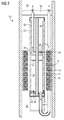
- a device 10 for fracturing the formation rock of oil or gas wells comprises a cylindrical mantle 12 which fits the inside of the well's casing 14.
- the stator part 16 of an electrical linear motor 18 is mounted on the inner surface of the mantle 12.
- the moveable part 20 of the linear motor 18 forms a chamber enclosing a fixed piston 22.
- the chamber 20 is closed against the inner volume of the casing 14 by end plates 24, which contain check valves 26 to allow the influx of fluid into the chamber 20.
- the piston 22 is fixed to a hollow tube 28 which extends throughout the device 10 and through the device's end plate 30 and opens into the space 32 in the casing 14 above the device 10.
- the tube 28 further connects to the hollow interior 34 of the piston 22, which in turn is connected to the space 36 above and the space 38 below the piston with respective check valves 26 allowing fluid to enter the piston 22.
- the chamber 20 moves periodically up and down relative to the piston 22, alternatively compressing the fluid in the spaces 36, 38, while the check valves 26 allow for a slow reequilibration of pressure.
- the compression waves generated this way propagate through the borehole and into the formation rock, where they induce the desired fracturing.
- FIG 2 An alternative design is depicted in FIG 2 .
- the chamber 20 is fixed relative to the stator 16, while the piston 22 forms the moveable part of the linear motor 18.
- the piston 22 is solid and moves on a solid axis 40.
- the space 36 above the piston 22 is connected to the space 32 above the device 10 by a first tube 42 with a check valve 26 opening to the space 32.
- the space 38 below the piston 22 connects to the space 32 via a second tube 44 with a check valve 26 also opening to the space 32.
- Another check valve 26 in the lower end plate 24 of the chamber 22 allows fluid to enter the lower space 38, whereas a check valve 26 in the upper end plate 24 of the chamber serves as point of entry for fluids into the upper space 36.
- the localized application of pressure by using the device 10 helps to constrain the fracturing to the oil or gas bearing formation itself and to avoid damage to the overburden, alleviating environmental concerns associated with conventional fracturing techniques, such as the contamination of aquifers by fracturing fluids.
Landscapes
- Life Sciences & Earth Sciences (AREA)
- Engineering & Computer Science (AREA)
- Geology (AREA)
- Mining & Mineral Resources (AREA)
- Physics & Mathematics (AREA)
- Environmental & Geological Engineering (AREA)
- Fluid Mechanics (AREA)
- General Life Sciences & Earth Sciences (AREA)
- Geochemistry & Mineralogy (AREA)
- Reciprocating Pumps (AREA)
Priority Applications (1)
| Application Number | Priority Date | Filing Date | Title |
|---|---|---|---|
| EP12191755.3A EP2730740A1 (fr) | 2012-11-08 | 2012-11-08 | Dispositif pour briser une roche de formation d'un puits |
Applications Claiming Priority (1)
| Application Number | Priority Date | Filing Date | Title |
|---|---|---|---|
| EP12191755.3A EP2730740A1 (fr) | 2012-11-08 | 2012-11-08 | Dispositif pour briser une roche de formation d'un puits |
Publications (1)
| Publication Number | Publication Date |
|---|---|
| EP2730740A1 true EP2730740A1 (fr) | 2014-05-14 |
Family
ID=47172485
Family Applications (1)
| Application Number | Title | Priority Date | Filing Date |
|---|---|---|---|
| EP12191755.3A Withdrawn EP2730740A1 (fr) | 2012-11-08 | 2012-11-08 | Dispositif pour briser une roche de formation d'un puits |
Country Status (1)
| Country | Link |
|---|---|
| EP (1) | EP2730740A1 (fr) |
Cited By (1)
| Publication number | Priority date | Publication date | Assignee | Title |
|---|---|---|---|---|
| WO2020103393A1 (fr) * | 2018-11-21 | 2020-05-28 | 重庆地质矿产研究院 | Outil de fracturation hydraulique à impulsions de type à scellage de fond de courroie de traînage de tube spiralé et procédé |
Citations (2)
| Publication number | Priority date | Publication date | Assignee | Title |
|---|---|---|---|---|
| US3422760A (en) | 1966-10-05 | 1969-01-21 | Petroleum Tool Research Inc | Gas-generating device for stimulating the flow of well fluids |
| US20050260089A1 (en) * | 2001-03-13 | 2005-11-24 | Baker Hughes Incorporated | Reciprocating pulser for mud pulse telemetry |
-
2012
- 2012-11-08 EP EP12191755.3A patent/EP2730740A1/fr not_active Withdrawn
Patent Citations (2)
| Publication number | Priority date | Publication date | Assignee | Title |
|---|---|---|---|---|
| US3422760A (en) | 1966-10-05 | 1969-01-21 | Petroleum Tool Research Inc | Gas-generating device for stimulating the flow of well fluids |
| US20050260089A1 (en) * | 2001-03-13 | 2005-11-24 | Baker Hughes Incorporated | Reciprocating pulser for mud pulse telemetry |
Cited By (2)
| Publication number | Priority date | Publication date | Assignee | Title |
|---|---|---|---|---|
| WO2020103393A1 (fr) * | 2018-11-21 | 2020-05-28 | 重庆地质矿产研究院 | Outil de fracturation hydraulique à impulsions de type à scellage de fond de courroie de traînage de tube spiralé et procédé |
| US11098566B2 (en) | 2018-11-21 | 2021-08-24 | Chongqing Institute Of Geology And Mineral Resources | Pulse hydraulic fracturing tool and method for coiled tubing dragging with bottom packer |
Similar Documents
| Publication | Publication Date | Title |
|---|---|---|
| US5950726A (en) | Increased oil and gas production using elastic-wave stimulation | |
| AU2013239809B2 (en) | Electrofracturing formations | |
| RU2136851C1 (ru) | Способ эксплуатации скважины | |
| RU2011129976A (ru) | Способ повышения эффективности нагнетания и интенсификации добычи нефти и газа | |
| US9841523B2 (en) | Tube wave generation | |
| CN113187441B (zh) | 一种深部煤层气与浅层低压致密气分压合采装置及方法 | |
| RU2547873C1 (ru) | Способ воздействия на угольный пласт через скважины, пробуренные из горных выработок | |
| EP2730740A1 (fr) | Dispositif pour briser une roche de formation d'un puits | |
| CN102619496A (zh) | 含油气岩分层分段多级爆破扩孔增裂方法 | |
| WO2017179072A1 (fr) | Fracturation assistée par ondes de choc utilisant la détonation d'un mélange de gaz détonnant | |
| CN106368664A (zh) | 一种脉冲式压裂滑套 | |
| US20130153211A1 (en) | Wave stimulation | |
| RU156338U1 (ru) | Устройство для создания перфорационных каналов в скважине | |
| RU2188322C1 (ru) | Способ гидравлической обработки угольного пласта | |
| RU2139405C1 (ru) | Установка для волнового воздействия на залежь | |
| EA201301096A1 (ru) | Устройство для гидромеханической перфорации скважин и обработки призабойной зоны пласта (варианты) | |
| RU2513805C1 (ru) | Способ повышения проницаемости угольного пласта через скважины, пробуренные из горных выработок | |
| RU2383720C1 (ru) | Способ обработки призабойной зоны скважины | |
| NO314419B1 (no) | Anordning og fremgangsmåte for fylling av fluid i en underjordisk formasjon | |
| RU60132U1 (ru) | Устройство для перфорирования скважин | |
| RU2000125925A (ru) | Способ гидроразрыва пластов в скважинах | |
| CA2930355C (fr) | Methode d'etancheisation d'ouverture d'un equipement de trou de forage | |
| RU2297516C2 (ru) | Устройство гидроимпульсного воздействия на пласт | |
| CA2987608C (fr) | Ensembles de pompe et d'outil d'extraction d'hydrocarbures | |
| RU2583804C1 (ru) | Устройство для импульсного воздействия на пласт |
Legal Events
| Date | Code | Title | Description |
|---|---|---|---|
| PUAI | Public reference made under article 153(3) epc to a published international application that has entered the european phase |
Free format text: ORIGINAL CODE: 0009012 |
|
| 17P | Request for examination filed |
Effective date: 20121108 |
|
| AK | Designated contracting states |
Kind code of ref document: A1 Designated state(s): AL AT BE BG CH CY CZ DE DK EE ES FI FR GB GR HR HU IE IS IT LI LT LU LV MC MK MT NL NO PL PT RO RS SE SI SK SM TR |
|
| AX | Request for extension of the european patent |
Extension state: BA ME |
|
| STAA | Information on the status of an ep patent application or granted ep patent |
Free format text: STATUS: THE APPLICATION IS DEEMED TO BE WITHDRAWN |
|
| 18D | Application deemed to be withdrawn |
Effective date: 20141115 |