EP2730741A2 - Compresseur à spirales - Google Patents
Compresseur à spirales Download PDFInfo
- Publication number
- EP2730741A2 EP2730741A2 EP13192389.8A EP13192389A EP2730741A2 EP 2730741 A2 EP2730741 A2 EP 2730741A2 EP 13192389 A EP13192389 A EP 13192389A EP 2730741 A2 EP2730741 A2 EP 2730741A2
- Authority
- EP
- European Patent Office
- Prior art keywords
- movable
- scroll
- movable member
- void
- shaft support
- Prior art date
- Legal status (The legal status is an assumption and is not a legal conclusion. Google has not performed a legal analysis and makes no representation as to the accuracy of the status listed.)
- Withdrawn
Links
- 230000006835 compression Effects 0.000 claims abstract description 26
- 238000007906 compression Methods 0.000 claims abstract description 26
- 239000011800 void material Substances 0.000 claims description 48
- 239000003507 refrigerant Substances 0.000 claims description 31
- 230000003247 decreasing effect Effects 0.000 claims description 8
- 239000003921 oil Substances 0.000 description 11
- 229910052751 metal Inorganic materials 0.000 description 9
- 239000002184 metal Substances 0.000 description 9
- 230000002093 peripheral effect Effects 0.000 description 8
- 239000010687 lubricating oil Substances 0.000 description 5
- 238000003780 insertion Methods 0.000 description 4
- 230000037431 insertion Effects 0.000 description 4
- 230000007423 decrease Effects 0.000 description 3
- 229910052782 aluminium Inorganic materials 0.000 description 2
- XAGFODPZIPBFFR-UHFFFAOYSA-N aluminium Chemical compound [Al] XAGFODPZIPBFFR-UHFFFAOYSA-N 0.000 description 2
- 239000011521 glass Substances 0.000 description 2
- 239000012212 insulator Substances 0.000 description 2
- 238000007789 sealing Methods 0.000 description 2
- 238000004378 air conditioning Methods 0.000 description 1
- 238000007599 discharging Methods 0.000 description 1
- 239000011347 resin Substances 0.000 description 1
- 229920005989 resin Polymers 0.000 description 1
Images



Classifications
-
- F—MECHANICAL ENGINEERING; LIGHTING; HEATING; WEAPONS; BLASTING
- F04—POSITIVE - DISPLACEMENT MACHINES FOR LIQUIDS; PUMPS FOR LIQUIDS OR ELASTIC FLUIDS
- F04C—ROTARY-PISTON, OR OSCILLATING-PISTON, POSITIVE-DISPLACEMENT MACHINES FOR LIQUIDS; ROTARY-PISTON, OR OSCILLATING-PISTON, POSITIVE-DISPLACEMENT PUMPS
- F04C14/00—Control of, monitoring of, or safety arrangements for, machines, pumps or pumping installations
-
- F—MECHANICAL ENGINEERING; LIGHTING; HEATING; WEAPONS; BLASTING
- F04—POSITIVE - DISPLACEMENT MACHINES FOR LIQUIDS; PUMPS FOR LIQUIDS OR ELASTIC FLUIDS
- F04C—ROTARY-PISTON, OR OSCILLATING-PISTON, POSITIVE-DISPLACEMENT MACHINES FOR LIQUIDS; ROTARY-PISTON, OR OSCILLATING-PISTON, POSITIVE-DISPLACEMENT PUMPS
- F04C28/00—Control of, monitoring of, or safety arrangements for, pumps or pumping installations specially adapted for elastic fluids
- F04C28/18—Control of, monitoring of, or safety arrangements for, pumps or pumping installations specially adapted for elastic fluids characterised by varying the volume of the working chamber
- F04C28/22—Control of, monitoring of, or safety arrangements for, pumps or pumping installations specially adapted for elastic fluids characterised by varying the volume of the working chamber by changing the eccentricity between cooperating members
-
- F—MECHANICAL ENGINEERING; LIGHTING; HEATING; WEAPONS; BLASTING
- F01—MACHINES OR ENGINES IN GENERAL; ENGINE PLANTS IN GENERAL; STEAM ENGINES
- F01C—ROTARY-PISTON OR OSCILLATING-PISTON MACHINES OR ENGINES
- F01C17/00—Arrangements for drive of co-operating members, e.g. for rotary piston and casing
- F01C17/06—Arrangements for drive of co-operating members, e.g. for rotary piston and casing using cranks, universal joints or similar elements
-
- F—MECHANICAL ENGINEERING; LIGHTING; HEATING; WEAPONS; BLASTING
- F04—POSITIVE - DISPLACEMENT MACHINES FOR LIQUIDS; PUMPS FOR LIQUIDS OR ELASTIC FLUIDS
- F04C—ROTARY-PISTON, OR OSCILLATING-PISTON, POSITIVE-DISPLACEMENT MACHINES FOR LIQUIDS; ROTARY-PISTON, OR OSCILLATING-PISTON, POSITIVE-DISPLACEMENT PUMPS
- F04C18/00—Rotary-piston pumps specially adapted for elastic fluids
- F04C18/02—Rotary-piston pumps specially adapted for elastic fluids of arcuate-engagement type, i.e. with circular translatory movement of co-operating members, each member having the same number of teeth or tooth-equivalents
-
- F—MECHANICAL ENGINEERING; LIGHTING; HEATING; WEAPONS; BLASTING
- F04—POSITIVE - DISPLACEMENT MACHINES FOR LIQUIDS; PUMPS FOR LIQUIDS OR ELASTIC FLUIDS
- F04C—ROTARY-PISTON, OR OSCILLATING-PISTON, POSITIVE-DISPLACEMENT MACHINES FOR LIQUIDS; ROTARY-PISTON, OR OSCILLATING-PISTON, POSITIVE-DISPLACEMENT PUMPS
- F04C18/00—Rotary-piston pumps specially adapted for elastic fluids
- F04C18/02—Rotary-piston pumps specially adapted for elastic fluids of arcuate-engagement type, i.e. with circular translatory movement of co-operating members, each member having the same number of teeth or tooth-equivalents
- F04C18/0207—Rotary-piston pumps specially adapted for elastic fluids of arcuate-engagement type, i.e. with circular translatory movement of co-operating members, each member having the same number of teeth or tooth-equivalents both members having co-operating elements in spiral form
- F04C18/0215—Rotary-piston pumps specially adapted for elastic fluids of arcuate-engagement type, i.e. with circular translatory movement of co-operating members, each member having the same number of teeth or tooth-equivalents both members having co-operating elements in spiral form where only one member is moving
-
- F—MECHANICAL ENGINEERING; LIGHTING; HEATING; WEAPONS; BLASTING
- F04—POSITIVE - DISPLACEMENT MACHINES FOR LIQUIDS; PUMPS FOR LIQUIDS OR ELASTIC FLUIDS
- F04C—ROTARY-PISTON, OR OSCILLATING-PISTON, POSITIVE-DISPLACEMENT MACHINES FOR LIQUIDS; ROTARY-PISTON, OR OSCILLATING-PISTON, POSITIVE-DISPLACEMENT PUMPS
- F04C18/00—Rotary-piston pumps specially adapted for elastic fluids
- F04C18/02—Rotary-piston pumps specially adapted for elastic fluids of arcuate-engagement type, i.e. with circular translatory movement of co-operating members, each member having the same number of teeth or tooth-equivalents
- F04C18/0207—Rotary-piston pumps specially adapted for elastic fluids of arcuate-engagement type, i.e. with circular translatory movement of co-operating members, each member having the same number of teeth or tooth-equivalents both members having co-operating elements in spiral form
- F04C18/0246—Details concerning the involute wraps or their base, e.g. geometry
- F04C18/0253—Details concerning the base
- F04C18/0261—Details of the ports, e.g. location, number, geometry
-
- F—MECHANICAL ENGINEERING; LIGHTING; HEATING; WEAPONS; BLASTING
- F04—POSITIVE - DISPLACEMENT MACHINES FOR LIQUIDS; PUMPS FOR LIQUIDS OR ELASTIC FLUIDS
- F04C—ROTARY-PISTON, OR OSCILLATING-PISTON, POSITIVE-DISPLACEMENT MACHINES FOR LIQUIDS; ROTARY-PISTON, OR OSCILLATING-PISTON, POSITIVE-DISPLACEMENT PUMPS
- F04C28/00—Control of, monitoring of, or safety arrangements for, pumps or pumping installations specially adapted for elastic fluids
- F04C28/08—Control of, monitoring of, or safety arrangements for, pumps or pumping installations specially adapted for elastic fluids characterised by varying the rotational speed
-
- F—MECHANICAL ENGINEERING; LIGHTING; HEATING; WEAPONS; BLASTING
- F04—POSITIVE - DISPLACEMENT MACHINES FOR LIQUIDS; PUMPS FOR LIQUIDS OR ELASTIC FLUIDS
- F04C—ROTARY-PISTON, OR OSCILLATING-PISTON, POSITIVE-DISPLACEMENT MACHINES FOR LIQUIDS; ROTARY-PISTON, OR OSCILLATING-PISTON, POSITIVE-DISPLACEMENT PUMPS
- F04C2270/00—Control; Monitoring or safety arrangements
- F04C2270/13—Noise
-
- F—MECHANICAL ENGINEERING; LIGHTING; HEATING; WEAPONS; BLASTING
- F04—POSITIVE - DISPLACEMENT MACHINES FOR LIQUIDS; PUMPS FOR LIQUIDS OR ELASTIC FLUIDS
- F04C—ROTARY-PISTON, OR OSCILLATING-PISTON, POSITIVE-DISPLACEMENT MACHINES FOR LIQUIDS; ROTARY-PISTON, OR OSCILLATING-PISTON, POSITIVE-DISPLACEMENT PUMPS
- F04C27/00—Sealing arrangements in rotary-piston pumps specially adapted for elastic fluids
- F04C27/001—Radial sealings for working fluid
Definitions
- the present invention relates to a scroll compressor.
- a scroll compressor includes a fixed scroll, which is fixed to a housing, and a movable scroll, which orbits with respect to the fixed scroll.
- the fixed scroll includes a fixed base plate and a fixed spiral wall projecting from the fixed base plate.
- the movable scroll includes a movable base plate and a movable spiral wall projecting from the movable base plate.
- the fixed spiral wall and the movable spiral wall are engaged with each other to define a compression chamber.
- the orbital movement of the movable scroll decreases the volume of the compression chamber and compresses refrigerant.
- Japanese Laid-Open Patent Publication No. 2010-14108 describes an example of such a scroll compressor.
- one aspect of the present invention is a scroll compressor that includes a rotation shaft, a fixed scroll including a fixed spiral wall, and a movable scroll including a movable spiral wall engaged with the fixed spiral wall.
- the movable scroll orbits when the rotation shaft is rotated.
- a compression chamber is defined between the fixed spiral wall and the movable spiral wall.
- the compression chamber has a volume that is decreased when the movable scroll orbits, and refrigerant is compressed in the compression chamber when the volume is decreased.
- a shaft support supports the rotation shaft.
- the shaft support and the fixed scroll are arranged at opposite sides of the movable scroll.
- a housing accommodates the rotation shaft, the fixed scroll, the movable scroll, and the shaft support.
- a movable member is arranged in the shaft support.
- a rotation restriction mechanism is configured to restrict rotation of the movable scroll.
- the rotation restriction mechanism includes a plurality of pins, a plurality of recesses into which the respective pins are loosely fitted, and the movable member.
- the movable member includes one of the plurality of pins and the plurality of recesses.
- a switching mechanism is configured to switch the movable member between a state in which movement of the movable member in a radial direction of the rotation shaft is restricted and a state in which the restriction is canceled and the movable member can move freely, which changes a movable range of the movable member in the radial direction of the rotation shaft so that an orbital radius of the movable scroll is changed.
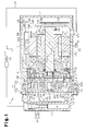
- a scroll compressor (hereinafter referred to as the compressor) will now be described.
- the compressor is installed in a vehicle and used with a vehicle air-conditioning device.
- the compressor 10 includes a housing 11 made of metal (aluminum in the present embodiment).
- the housing 11 includes a cylindrical motor housing member 12 and a cylindrical discharge housing member 13.
- the motor housing member 12 includes a closed end and an open end 121h (left end as viewed in Fig. 1 ).
- the discharge housing member 13, which has a closed end, is connected to the open end 121h of the motor housing member 12.
- the motor housing member 12 accommodates a compression unit P, which compresses refrigerant, and an electric motor M, which drives the compression unit P.
- the motor housing member 12 includes an end wall 12a and a cylindrical shaft support portion 121a projecting from the central section of the end wall 12a.
- a shaft support 21 is fixed in the motor housing member 12 near the open end 121h.
- An insertion hole 21a extends through a central section of the shaft support 21.
- the motor housing member 12 also accommodates a rotation shaft 20.
- the rotation shaft 20 includes two ends. One end, which faces toward the open end 121h of the motor housing member 12, is located in the insertion hole 21a of the shaft support 21 and supported by a bearing B1 to be rotatable relative to the shaft support 21.
- the other end of the rotation shaft 20 faces toward the end wall 12a of the motor housing member 12 and is supported by a bearing B2 to be rotatable relative to the shaft support portion 121a.
- the bearings B1 and B2 are plain bearings.
- the motor housing member 12 includes a motor chamber 121 extending between the shaft support 21 and the end wall 12a.
- the motor chamber 121 accommodates the electric motor M that includes a rotor 16, which rotates integrally with the rotation shaft 20, and a stator 17, which surrounds the rotor 16 and is fixed to the inner surface of the motor housing member 12.
- the rotor 16 includes a rotor core 16a, which is fixed to the rotation shaft 20 and rotated integrally with the rotation shaft 20, and a plurality of permanent magnets 16b, which are embedded in the rotor core 16a.
- the stator 17 includes a stator core 17a, which is annular and fixed to the inner surface of the motor housing member 12, and coils 17b, which are wound around the teeth (not shown) of the stator core 17a.
- Leads R for U, V, and W phases (only one lead shown in Fig. 1 ) extend from the ends of the coils 17b that face toward the shaft support 21.
- a fixed scroll 22 is arranged between the shaft support 21 and the open end 121h of the motor housing member 12.
- the fixed scroll 22 includes a circular base plate 22a, a cylindrically-formed peripheral wall 22b projecting from the periphery of the base plate 22a, and a fixed spiral wall 22c projecting from the base plate 22a at the inner side of the peripheral wall 22b.
- An eccentric shaft 20a projects from the end face of the rotation shaft 20 that faces toward the open end 121 h.
- the eccentric shaft 20a is eccentric to the rotation axis L of the rotation shaft 20.
- the eccentric shaft 20a supports a bushing 20b.
- a movable scroll 23 is supported by the bushing 20b to be rotatable relative to the bushing 20b.
- a bearing B3 is arranged between the movable scroll 23 and the bushing 20b.
- the movable scroll 23 includes a circular base plate 23a and a movable spiral wall 23b projecting from the base plate 23a toward the base plate 22a of the fixed scroll 22.
- the fixed spiral wall 22c of the fixed scroll 22 and the movable spiral wall 23b of the movable scroll 23 are engaged with each other.
- the fixed spiral wall 22c has a distal surface in contact with the base plate 23a of the movable scroll 23.
- the movable spiral wall 23b has a distal surface in contact with the base plate 22a of the fixed scroll 22.
- the base plate 22a and the fixed spiral wall 22c of the fixed scroll 22 and the base plate 23a and the movable spiral wall 23b of the movable scroll 23 define a compression chamber 25.
- the end surface of the shaft support 21 that faces the movable scroll 23 includes an accommodating recess 21 h.
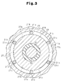
- the accommodating recess 21h accommodates an annular movable member 28 surrounding the bushing 20b.
- a clearance C1 is formed between the movable member 28 and the shaft support 21 in the radial direction of the rotation shaft 20.
- the movable member 28 is movable in the radial direction of the rotation shaft 20 in the range of a distance corresponding to the clearance C1.
- the terms "axial direction”, “radial direction”, and “circumferential direction” refer to the axial direction, the radial direction, and the circumferential direction of the rotation shaft 20, respectively.
- a rotation restriction mechanism 27 is arranged between the base plate 23a of the movable scroll 23 and the shaft support 21.
- the rotation restriction mechanism 27 includes a plurality of circular holes 27a, which are recesses arranged in the outer circumferential portion of the end surface of the base plate 23a of the movable scroll 23, and a plurality of pins 27b (only one shown in Fig. 1 ), which project from the outer circumferential portion of the shaft support 21 and are loosely fitted into the circular holes 27a.
- the pins 27b are integrated with the movable member 28.
- the shaft support 21 includes a plurality of cylindrical valve chambers 21 b extending in the axial direction.
- the valve chambers 21b are arranged in intervals in the circumferential direction.
- Each valve chamber 21b has one end facing toward the movable scroll 23 that opens in the accommodating recess 21h and another end facing away from the movable scroll 23 that is closed by a cover 21f, which has the form of a circular plate.
- the cover 21f is coupled to the end surface of the shaft support 21 that faces toward the end wall 12a of the motor housing member 12.
- Each valve chamber 21b accommodates a cylindrical valve body 21v.
- Each valve body 21v has a semispherical distal end that faces toward the movable scroll 23.
- An annular seal 21s is arranged in the outer surface of each valve body 21v. The seal 21s seals the gap between the valve body 21v and the valve chamber 21b and divides the valve chamber 21 b into a primary void K1 and a secondary void K2.
- the primary void K1 is located between the movable scroll 23 and the secondary void K2.
- the shaft support 21 incorporates an electromagnetic switching valve 70.
- the shaft support 21 includes a branch passage 71 extending from the switching valve 70 to the valve chambers 21 b.
- the branch passage 71 includes a main passage 71a, which is in communication with the switching valve 70, and an annular passage 71 b, which extends in the circumferential direction and communicates the main passage 71a and the secondary voids K2 of the valve chambers 21b.
- the end surface of the movable member 28 that faces away from the movable scroll 23 includes circular fitting recesses 28k at positions corresponding to the valve chambers 21b.
- the surface of each fitting recess 28k is tapered so that the diameter of the fitting recess 28k increases from the side that faces toward the movable scroll 23 to the end surface that faces away from the movable scroll 23.
- the movable member 28 also includes communication passages 28r that extend in the axial direction and are in communication with the corresponding fitting recesses 28k.
- An annular, flat seat member 24 is arranged between the movable scroll 23 and the movable member 28.
- the seat member 24 includes a peripheral portion held between the fixed scroll 22 and the shaft support 21.
- the seat member 24 is fixed positioned relative to the motor housing member 12.
- the seat member 24 includes communication holes 24g that communicate the corresponding communication passages 28r and a gap between the seat member 24 and the movable scroll 23.
- the movable scroll 23 which is coupled to the rotation shaft 20 by the eccentric shaft 20a, orbits about the axis of the fixed scroll 22 (the rotation axis L of the rotation shaft 20) without rotating.
- the rotation restriction mechanism 27 prevents rotation of the movable scroll 23 while permitting the orbital motion.
- the orbital motion of the movable scroll 23 reduces the volume of the compression chamber 25.
- the fixed scroll 22 and the movable scroll 23 form a compression unit P that draws in and discharges refrigerant.
- the peripheral wall 22b of the fixed scroll 22 and the outermost portion in the movable spiral wall 23b of the movable scroll 23 define a suction chamber 31 that is in communication with the compression chamber 25.
- the peripheral wall 22b of the fixed scroll 22 has an outer surface including a recess 221 b.
- the area surrounded by the recess 221 b and the inner surface of the motor housing member 12 forms a suction passage 32 that is connected to the suction chamber 31 through a through hole 221 h in the peripheral wall 22b of the fixed scroll 22.
- the motor housing member 12 includes a suction port 122 connected to an external refrigerant circuit 19.
- Refrigerant gas
- the refrigerant in the motor chamber 121 is then sent to the compression chamber 25 through the through hole 211, the through hole 24h, the suction passage 32, the through hole 221 h, and the suction chamber 31.
- the motor chamber 121, the through hole 211, the through hole 24h, the suction passage 32, the through hole 221h, and the suction chamber 31 form a suction pressure region.
- the refrigerant in the compression chamber 25 is compressed by the orbiting motion (discharging motion) of the movable scroll 23, forced through a discharge valve 22v of a discharge port 22e, and discharged into a discharge chamber 131 of the discharge housing member 13.
- a chamber-forming wall 41 is formed integrally with the discharge housing member 13.
- An oil-separating chamber 42 is formed between the discharge housing member 13 and the chamber-forming wall 41.
- the oil-separating chamber 42 is in communication with the discharge chamber 131 through a discharge port 43 formed in the discharge housing member 13.
- the refrigerant in the discharge chamber 131 is sent to the oil-separating chamber 42 through the discharge port 43.
- the oil-separating chamber 42 accommodates an oil-separating cylinder 44.
- the oil-separating cylinder 44 includes a large diameter portion 441, which is fitted in the oil-separating chamber 42, and a small diameter portion 442, which has a smaller diameter than the oil-separating chamber 42 and is located under the large diameter portion 441.
- Refrigerant flows into the oil-separating chamber 42 through the discharge port 43, swirls around the small diameter portion 442, and then flows into the oil-separating cylinder 44 from a lower opening in the small diameter portion 442.
- the refrigerant further flows from the oil-separating cylinder 44 to the external refrigerant circuit 19 and then returns to the motor chamber 121.
- Lubricating oil is separated from the refrigerant when the refrigerant swirls around the small diameter portion 442.
- the separated lubricating oil falls into the lower portion of the oil-separating chamber 42. Accordingly, the discharge port 22e, the discharge chamber 131, the discharge port 43, and the oil-separating chamber 42 form a discharge pressure region.
- An inverter cover 51 made of metal (aluminum in the present embodiment) is fixed to the end wall 12a of the motor housing member 12.
- the inverter cover 51 and the end wall 12a of the motor housing member 12 define a chamber that accommodates a motor driving circuit 52 fixed to the outer surface of the end wall 12a.
- the compression unit P, the electric motor M, and the motor driving circuit 52 are arranged in this order in the axial direction.
- the end wall 12a of the motor housing member 12 includes a through hole 12b that receives a sealing terminal 53.
- the sealing terminal 53 includes three sets of a metal terminal 54 and a glass insulator 55 (only one set shown in Fig. 1 ).
- the metal terminals 54 extend through the motor housing member 12 to electrically connect the electric motor M to the motor driving circuit 52.
- Each glass insulator 55 fixes the corresponding metal terminal 54 to the end wall 12a and insulates the metal terminal 54 from the end wall 12a.
- Each metal terminal 54 has a first end connected to the motor driving circuit 52 by a cable (not shown) and a second end extending into the motor housing member 12.
- An insulative resin cluster block 56 is fixed to the outer surface of the stator core 17a.
- the cluster block 56 accommodates three connection terminals 56a (only one shown in the Fig. 1 ).
- the connection terminals 56a electrically connect the leads R to the metal terminals 54.
- the motor driving circuit 52 supplies power to the coils 17b through the metal terminals 54, the connection terminals 56a, and the leads R. This integrally rotates the rotor 16 and the rotation shaft 20.
- an annular seal 61 which is in contact with the surface of the rotation shaft 20, divides the insertion hole 21a of the shaft support 21 into a back pressure chamber 62 and an accommodating chamber 63.
- the back pressure chamber 62 is located between the seal 61 and the movable scroll 23.
- the accommodating chamber 63 accommodates the bearing B1.
- a snap ring 64 is fitted to a section of the insertion hole 21a of the shaft support 21 that is located in the back pressure chamber 62. The snap ring 64 restricts movement of the seal 61 into the back pressure chamber 62.
- the movable scroll 23 and the seat member 24 include a first oil passage 65 extending through the movable spiral wall 23b and the base plate 23a near the center of the movable scroll 23.
- the first oil passage 65 has an end that opens to the compression chamber 25 and another end that opens to the back pressure chamber 62. Some of the refrigerant compressed in the compression chamber 25 is supplied to the back pressure chamber 62 through the first oil passage 65.
- the refrigerant supplied to the back pressure chamber 62 flows through the inner side of the seat member 24 into the circular holes 27a. The pressure of the refrigerant supplied into the back pressure chamber 62 and the circular holes 27a presses the movable scroll 23 toward the fixed scroll 22.
- the circular holes 27a and the back pressure chamber 62 form a back pressure region located between the movable scroll 23 and the movable member 28 in the motor housing member 12.
- the back pressure region applies force to the movable scroll 23, and the force presses the movable scroll 23 against the fixed scroll 22.
- the refrigerant When refrigerant enters the gap between the seat member 24 and the movable scroll 23, the refrigerant flows to the primary voids K1 of the valve chambers 21b through the corresponding communication holes 24g and the communication passages 28r.
- the primary voids K1 function as part of the back pressure region due to the pressure of the refrigerant flowing into the primary voids K1.
- the switching valve 70 is in communication with the oil-separating chamber 42 through the second oil passage 68, which extends through the shaft support 21, the seat member 24, the fixed scroll 22, and the discharge housing member 13. Further, the switching valve 70 is in communication with the motor chamber 121 through a communication passage 69 formed in the shaft support 21 and the cover 21f.
- the switching valve 70 operates so that the secondary voids K2 of the valve chambers 21b are in communication with the second oil passage 68 through the branch passage 71 when the compressor 10 operates at a high rotation speed and so that the secondary voids K2 are in communication with the communication passage 69 through the branch passage 71 when the compressor 10 operates at a low rotation speed.
- the switching valve 70 switches between a state in which the secondary voids K2 are in communication with a suction pressure region and a state in which the secondary voids K2 are in communication with a discharge pressure region.
- the suction pressure region is a low pressure region, the pressure of which is lower than that of the primary voids K1.
- the primary voids K1 are part of the back pressure region.
- the discharge pressure region is a high pressure region, the pressure of which is higher than that of the primary voids K1.
- the switching valve 70 brings the secondary voids K2 of the valve chambers 21b into communication with the second oil passage 68 through the branch passage 71. This allows the lubricating oil flowing in the second oil passage 68 from the oil-separating chamber 42 to be sent into the secondary voids K2 of the valve chambers 21b through the switching valve 70 and the branch passage 71. Consequently, the secondary voids K2 become part of the discharge pressure region.
- the difference between the pressure in the primary voids K1 and the pressure in the secondary voids K2 moves the valve bodies 21v toward the movable scroll 23.
- the distal end of each valve body 21v that faces toward the movable scroll 23 is guided by the surface of the corresponding fitting recess 28k into the fitting recess 28k. Accordingly, the movable member 28 is pressed by the valve bodies 21v toward the movable scroll 23 and received by the seat member 24.
- the movable member 28 is held between the valve bodies 21v and the seat member 24. This restricts movement of the movable member in the radial direction.
- the engagement between the valve bodies 21v and the respective fitting recesses 28k also restricts the radial movement of the movable member 28 and changes the movable range of the movable member 28 in the radial direction.
- the orbital radius of the movable scroll 23 is decreased compared to when the restriction of the movable member 28 is canceled and the movable member 28 can move freely.
- the movable spiral wall 23b does not contact the fixed spiral wall 22c when the compressor 10 operates at a high rotation speed. This reduces noise that would be caused by contact between the fixed spiral wall 22c and the movable spiral wall 23b during high speed rotation.
- the switching valve 70 brings the secondary voids K2 of the valve chambers 21 b into communication with the communication passage 69 through the branch passage 71. This allows the refrigerant in the valve chambers 21b to flow into the motor chamber 121 through the branch passage 71, the switching valve 70, and the communication passage 69. Consequently, the secondary voids K2 become part of the suction pressure region.
- the difference in the pressure in the primary voids K1 and the pressure in the secondary voids K2 moves the valve bodies 21v away from the movable scroll 23.
- the movable range of the movable member 28 in the radial direction is changed.
- the orbital radius of the movable scroll 23 is increased compared to when the radial movement of the movable member 28 is restricted.
- the movable spiral wall 23b is in contact with the fixed spiral wall 22c when the compressor 10 operates at low rotation speed.
- valve chamber 21b, the valve body 21v, the primary void K1, the secondary void K2, the branch passage 71, and the switching valve 70 form a switching mechanism.
- the orbital radius of the movable scroll 23 is increased or decreased when the bushing 20b slides or swings to move in the radial direction relative to the eccentric shaft 20a and thereby permit radial movement of the movable scroll 23.
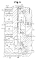
- the end surface of the movable member 28 that faces away from the movable scroll 23 includes a conical projection 81.
- the conical projection 81 includes a conical projection surface 81a that surrounds the bushing 20b and has a diameter that decreases as the movable scroll 23 becomes farther.
- an annular seal 28s is arranged in the outer circumferential surface of the movable member 28.
- the seal 28s has an outer surface that is located radially outward from the outer circumferential surface of the movable member 28. Accordingly, a clearance C2 is formed between the movable member 28 and the shaft support 21 in the radial direction.
- the seal 28s can be elastically deformed to allow the movable member 28 to move in the radial direction in the range of the distance of the clearance C2.
- the accommodating recess 21 h accommodates a tip seal 29 arranged on the end surface of the movable member 28 that faces away from the movable scroll 23.
- the tip seal 29 seals the gap between the shaft support 21 and the movable member 28.
- the end surface of the movable member 28 that faces away from the movable scroll 23 includes an accommodating groove 28g that can accommodate the tip seal 29.
- the accommodating recess 21h is divided into a primary void K1 and a secondary void K2.
- the primary void K1 is located between the movable scroll 23 and the secondary void K2, and the secondary void K2 is located between the seal 28s and the tip seal 29.
- the shaft support 21 includes a communication flow passage 83 that communicates the switching valve 70 and the secondary void K2.
- the primary void K1 is in communication with the first oil passage 65, which is in communication with the back pressure chamber 62.
- the primary void K1 functions as part of the back pressure region.
- the shaft support 21 includes a conical recess 82 on the side that faces the movable member 28.
- the conical recess 82 includes a conical recess surface 82a that surrounds the bushing 20b and has a diameter that decreases as the movable member 28 becomes farther.
- the conical projection 81 is movable toward and away from the conical recess 82.
- the switching valve 70 brings the secondary void K2 into communication with the communication passage 69 through the communication flow passage 83. This allows the refrigerant in the secondary void K2 to flow into the motor chamber 121 through the communication flow passage 83, the switching valve 70, and the communication passage 69. Consequently, the secondary void K2 becomes part of the suction pressure region.
- the difference between the pressure in the primary void K1 and the pressure in the secondary void K2 moves the movable member 28 away from the movable scroll 23.
- This moves the conical projection 81 toward the conical recess 82 and brings the conical projection surface 81a and conical recess surface 82a into contact with each other.
- the conical projection 81 is fitted into the conical recess 82 and thereby restricts the radial movement of the movable member 28.
- the orbital radius of the movable scroll 23 is decreased compared to when the movable member 28 is not restricted and freely movable.
- the switching valve 70 brings the secondary void K2 into communication with the second oil passage 68 through the communication flow passage 83. This allows the lubricating oil flowing in the second oil passage 68 from the oil-separating chamber 42 to flow into the secondary void K2 through the switching valve 70 and the communication flow passage 83. Consequently, the secondary void K2 becomes part of the discharge pressure region.
- the difference between the pressure in the primary void K1 and the pressure in the secondary void K2 moves the movable member 28 toward the movable scroll 23.
- This moves the conical projection 81 away from the conical recess 82 and allows the movable member 28 to move freely.
- the orbital radius of the movable scroll 23 is increased compared to when the radial movement of the movable member 28 is restricted.
- the conical projection 81, the conical recess 82, the primary void K1, the secondary void K2, the communication passage 69, and the switching valve 70 form a switching mechanism.
- the second embodiment has the following advantages in addition to advantage (1) of the first embodiment.
- the second embodiment does not require the valve chambers 21b or the valve bodies 21v of the first embodiment and has a simple structure.
- the movable member 28 does not have to include the fitting recesses 28k. Instead, the valve bodies 21v may be pressed against the end surface of the movable member 28 that faces away from the movable scroll 23 to restrict radial movement of the movable member 28 with the friction produced between the valve bodies 21v and the movable member 28.
- the communication passages 28r may be omitted.
- the primary voids K1 can still become the back pressure region due to the refrigerant flowing into the primary voids K1 from the back pressure chamber 62 through the gap between the movable member 28 and the shaft support 21.
- the number of the valve chambers 21b is not limited.
- the seat member 24 may be omitted.
- the radial movement of the movable member 28 may be restricted by holding the movable member 28 between the valve bodies 21v and the movable scroll 23, for example.
- the shape of the valve body 21v is not limited.
- the valve body 21v may be spherical.
- the surface of the fitting recesses 28k may extend in the axial direction, for example.
- the secondary void K2 does not have to be in communication with the suction pressure region or the discharge pressure region as long as the secondary void K2 is in communication with a low pressure region that has a lower pressure than the back pressure region or a high pressure region that has a higher pressure than the back pressure region.
- the bushing 20b may be fixed to the eccentric shaft 20a, and the radial movement of the movable scroll 23 may be permitted by a gap between the movable scroll 23 and the bearing B3 or a gap between the bushing 20b and the bearing B3.
- the secondary void K2 receives lubricating oil from the oil-separating chamber 42 through the second oil passage 68.
- the secondary void K2 may be in communication with the discharge chamber 131 so that refrigerant having the discharge pressure is delivered to the secondary void K2.
- the movable scroll 23 may include a plurality of pins that are integrated with the movable scroll 23, and the movable member 28 may include a plurality of circular holes into which the respective pins are loosely fitted.
- the present invention may be embodied in a scroll compressor that is directly driven by a driving source such as an engine, instead of being driven by the electric motor M.
Landscapes
- Engineering & Computer Science (AREA)
- Mechanical Engineering (AREA)
- General Engineering & Computer Science (AREA)
- Rotary Pumps (AREA)
- Applications Or Details Of Rotary Compressors (AREA)
Applications Claiming Priority (1)
| Application Number | Priority Date | Filing Date | Title |
|---|---|---|---|
| JP2012249186A JP6007737B2 (ja) | 2012-11-13 | 2012-11-13 | スクロール型圧縮機 |
Publications (1)
| Publication Number | Publication Date |
|---|---|
| EP2730741A2 true EP2730741A2 (fr) | 2014-05-14 |
Family
ID=49578147
Family Applications (1)
| Application Number | Title | Priority Date | Filing Date |
|---|---|---|---|
| EP13192389.8A Withdrawn EP2730741A2 (fr) | 2012-11-13 | 2013-11-11 | Compresseur à spirales |
Country Status (5)
| Country | Link |
|---|---|
| US (1) | US20140134033A1 (fr) |
| EP (1) | EP2730741A2 (fr) |
| JP (1) | JP6007737B2 (fr) |
| KR (1) | KR20140061251A (fr) |
| CN (1) | CN103807167A (fr) |
Families Citing this family (5)
| Publication number | Priority date | Publication date | Assignee | Title |
|---|---|---|---|---|
| JP5880398B2 (ja) * | 2012-11-13 | 2016-03-09 | 株式会社豊田自動織機 | スクロール型圧縮機 |
| CN108779675B (zh) * | 2016-02-25 | 2021-05-11 | 比泽尔制冷设备有限公司 | 压缩机 |
| KR102549777B1 (ko) * | 2016-12-21 | 2023-06-30 | 삼성전자주식회사 | 스크롤 압축기 |
| CN107605727A (zh) * | 2017-09-04 | 2018-01-19 | 珠海格力电器股份有限公司 | 涡旋压缩机 |
| JP6903826B2 (ja) * | 2018-02-28 | 2021-07-14 | 日立ジョンソンコントロールズ空調株式会社 | スクロール圧縮機における動的半径方向コンプライアンス |
Family Cites Families (6)
| Publication number | Priority date | Publication date | Assignee | Title |
|---|---|---|---|---|
| JPS57198386A (en) * | 1981-05-30 | 1982-12-04 | Sanden Corp | Scroll type fluid system |
| JP3560492B2 (ja) * | 1999-02-25 | 2004-09-02 | 株式会社日本自動車部品総合研究所 | スクロール型圧縮機 |
| JP2000352389A (ja) * | 1999-06-08 | 2000-12-19 | Mitsubishi Heavy Ind Ltd | スクロール圧縮機 |
| US6217302B1 (en) * | 2000-02-24 | 2001-04-17 | Scroll Technologies | Floating seal bias for reverse fun protection in scroll compressor |
| JP3913106B2 (ja) * | 2002-05-22 | 2007-05-09 | 株式会社デンソー | 可変容量型流体圧送機 |
| JP2006274970A (ja) * | 2005-03-30 | 2006-10-12 | Sanden Corp | スクロール圧縮機 |
-
2012
- 2012-11-13 JP JP2012249186A patent/JP6007737B2/ja active Active
-
2013
- 2013-11-08 KR KR1020130135552A patent/KR20140061251A/ko not_active Ceased
- 2013-11-11 CN CN201310556808.3A patent/CN103807167A/zh active Pending
- 2013-11-11 US US14/076,693 patent/US20140134033A1/en not_active Abandoned
- 2013-11-11 EP EP13192389.8A patent/EP2730741A2/fr not_active Withdrawn
Also Published As
| Publication number | Publication date |
|---|---|
| JP6007737B2 (ja) | 2016-10-12 |
| US20140134033A1 (en) | 2014-05-15 |
| JP2014098317A (ja) | 2014-05-29 |
| KR20140061251A (ko) | 2014-05-21 |
| CN103807167A (zh) | 2014-05-21 |
Similar Documents
| Publication | Publication Date | Title |
|---|---|---|
| US9181951B2 (en) | Scroll compressor | |
| EP2653726B1 (fr) | Compresseur motorisé | |
| CN212079622U (zh) | 电动机操作式压缩机 | |
| US20140134033A1 (en) | Scroll compressor | |
| US10396621B2 (en) | Electric compressor | |
| CN218235375U (zh) | 电动压缩机 | |
| KR20200140967A (ko) | 전동식 압축기 | |
| US12092104B2 (en) | Scroll compressor with a thrust plate and a flexible thrust sheet member | |
| EP2230405A1 (fr) | Dispositif de borne pour compresseur électrique | |
| US20230304493A1 (en) | Scroll compressor | |
| EP1867874A1 (fr) | Compresseur entraine par un moteur electrique | |
| KR20240141409A (ko) | 전동 압축기 | |
| JP7607510B2 (ja) | スクロール圧縮機 | |
| JP7638145B2 (ja) | スクロール圧縮機 | |
| JP2024060651A (ja) | 電動圧縮機 | |
| JP2024165852A (ja) | インバータ一体型電動圧縮機 | |
| EP1087141A2 (fr) | Compresseur à spirales | |
| WO2024237016A1 (fr) | Compresseur électrique à onduleur intégré | |
| CN114941622A (zh) | 涡旋式压缩机及具备该涡旋式压缩机的空调装置 | |
| KR20200140428A (ko) | 스크롤형 압축기 | |
| JP2005201256A (ja) | 電動圧縮機およびその組立方法 |
Legal Events
| Date | Code | Title | Description |
|---|---|---|---|
| PUAI | Public reference made under article 153(3) epc to a published international application that has entered the european phase |
Free format text: ORIGINAL CODE: 0009012 |
|
| 17P | Request for examination filed |
Effective date: 20131111 |
|
| AK | Designated contracting states |
Kind code of ref document: A2 Designated state(s): AL AT BE BG CH CY CZ DE DK EE ES FI FR GB GR HR HU IE IS IT LI LT LU LV MC MK MT NL NO PL PT RO RS SE SI SK SM TR |
|
| AX | Request for extension of the european patent |
Extension state: BA ME |
|
| STAA | Information on the status of an ep patent application or granted ep patent |
Free format text: STATUS: THE APPLICATION HAS BEEN WITHDRAWN |
|
| 18W | Application withdrawn |
Effective date: 20150714 |